Two New Engines

Home Model Engine Machinist Forum

Help Support Home Model Engine Machinist Forum:

This site may earn a commission from merchant affiliate links, including eBay, Amazon, and others.
"I hope it doesn't put you to sleep".

Hi Jerry,

Not one of your builds has me anywhere near asleep and nor could cutting Florida grass compete with what you do.
Also, I am sure I could speak for the majority on here who must feel the same, but who do not always post a comment, that they love to watch talented machinists build these wonderful creations.
I take the greatest pleasure in following these threads and to listen to the dialogue on the posted videos, as I do messer's Brian Rupnow, Chuck etc. Plus for Bogs comments and advice of whom I have made no replies to either. Perhaps it's time I did along with other "watchers"!!

Kind regards,

Ron.

PS, I have only mentioned a couple but there are so many talented people out there that I would have to mention almost every member!!

PPS. I have been a machinist for about 42 years and with some of you, I cannot compete on this scale.

Yet! Rof}
 
The real problem with Florida grass is the almost daily rain. The grass barely gets dry before the next rain. There are 10 acres here so you have to get to it when the opportunity presents itself. Things will get easier when my helper gets up to speed. I need to make some riser blocks for the clutch and brake pedals.

MarleyandElmer001.jpg


I'm just taking a iced tea break and decided to check in on the forum. I'll get to the valve post tonight but it will be late so look for it tomorrow.

Dan, I don't know how a Bilgram Diagram works and I don't really understand the Diagram part of the Zuener Diagram. My first advice is to put away the compass and straight edge and just work the numbers. It will be a long post so I'll get to it tonight


Jerry
 
Thanks to all who have expressed an interest in ANOTHER steam valve and my apologies to anyone who thought that I was going to explain how to construct a Zeuner Diagram. I can't.

What I said I would do is explain how I use Charles Dockstader's Zeuner Diagram to develop the dimension for this engine. I am not a steam engineer so when someone says "That would run better with a little more cutoff" I have to assume that he know what he is talking about. That's not really the problem that I need to solve right now.

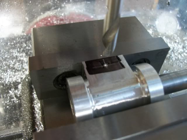
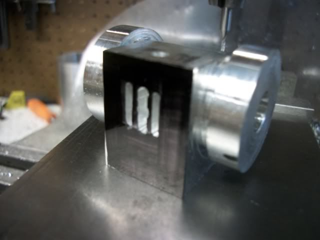
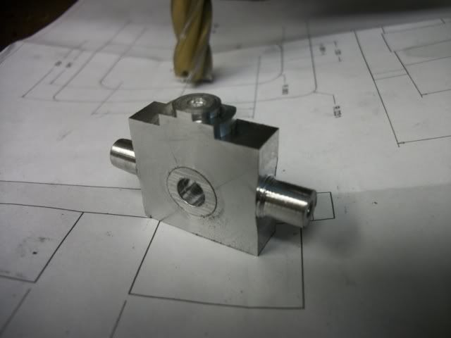
Right now I have a steam chest whose internal dimensions are .850" long by .650" high. The corners have a .063 radius from the 1/8" end mill that was used to make it so I have about .625" of working space for the D-valve. How do I establish the correct dimensions for the valve and how do I tweak it for performance.

this is where Charles Dockstader's Zeuner Diagram comes in. I'm afraid that I don't know who Zeuner was or any of the history of his diagram. Early engineers often used graphical means to resolve complex relationships with multiple factors and to visualize the affect that changes in one or more factors had on the result. Today's "What if" scenarios are plugged into a spread sheet. The value that Dockstader's program has is that it combines an interactive spreadsheet like interface with a digital as well as a graphical representation.

If you don't have the Dockstader prorams, ask Google where it is. Fire it up and select the "Zeuner Diagram" option in the lower right hand corner.

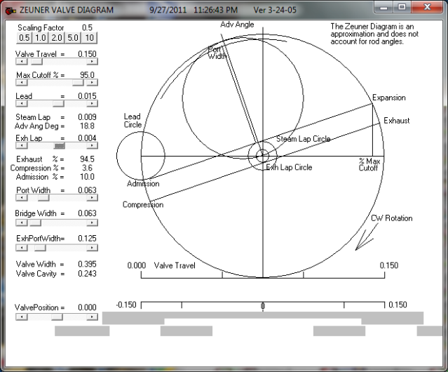
This opens up a screen that looks like this:

Final_Valve_Dimensions-1.png


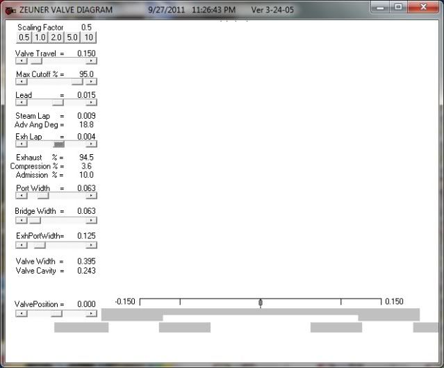
Unless you are used to solving complex relationships with a compass and a straight edge, I would recommend that you ignore the diagram and concentrate on the parameters column on the left. Like this:

Final_Valve_Dimensions.jpg


You can move any of the sliders in this column and see the effect that the change has. Ignore the diagram, it will drive you whacky!

Of the factors that you can change directly, only 4 are actual dimensions.

1. Valve travel (equal to eccentric throw)
2. Steam port width
3. Bridge width (distance between steam and exhaust port)
4. Exhaust port width

There are 2 dimensions that you will have to reproduce but cannot directly change on this program:
1 Width of valve (width of D-slide valve)
2 Width of cavity ( the width of the cavity in the face of the D-valve )

The other changeable factors are not direct dimensions. Changes to them will cause changes in one or both of the last two dimensions.

I hope no one says "well how about the length of the valve slots" to which I would have to answer "Huh?"

For reasons of simplicity, I will limit the width of the ports to end mills that I have and because of common practice, the exhaust port will be twice as wide as the steam port to allow for the increased volume of the expanded steam (even though I
plan to use compressed air) so the exhaust port will be 1/8" wide and the steam ports will be 1/16" wide. That leaves only the width of the space between the ports to determine. I will arbitrarily start with a 1/16" bridge width. The total width of the three slots is 3/8" almost twice that amount of space inside the steam chest. That will probably work and I did not need any higher math or exotic diagram to figure it out.

If I make these changes to the Dockstader input screen, the screen will display a needed valve width of .585" and because the starting point for valve travel is set at .500", travel plus body width = 1.085" which will not fit within my steam chest.
I will have to change the eccentric.

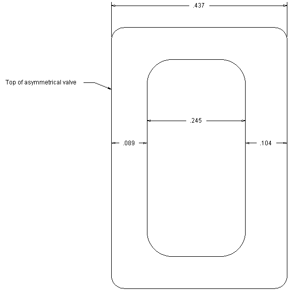
If I grab the valve traver slider and drag it to the right left, keeping an eye on the valve width dimension, at about .165" of valve travel, the combination of travel and valve width falls to just under .600" which will fit my steam chest. If I reduce the valve travel to .150", the valve width drops to .429" and the cavity width to .251"

The default values of 80% cutoff, and .015" lead can be reduced to 95% cutoff, and .010" lead bring the valve width to .400". and additional changes to cutoff and lead show a corresponding chnge to valve width.

Changing the exhaust lap from .000 to .010 reduces the valve cavity dimension to .231"

With this information, I have the ability to tweak the valve anyway that I want and if I find the possibility to change from air to steam, all I have to do is change the D-valve. Nothing on the valve face changes.

I hope I have made sense of this. Its very late and my eyelids are banging shut so I may have left something out or misstated. I'll look at it again tomorrow and add any clarification needed.

Jerry


Nice one CJ :bow:

Just a suggestion but try 0.7 as the starting point for cut off and double the lead for the bottom of the valve to account for the angles and weight of the gear on the up stroke. You end up with 2 diagrams for 1 valve. If you leave the lead the same then the diagram is simply reversed through 180o to show the steam v exhaust on the other stoke.

Hope this helps.

Best Regards
Bob

PS If there is any interest I can start a new thread on how to construct a Zeuner Diagram
 
Bob

Thanks for jumping in. I understand your suggestion up to a point, but I have some questions.

1. The calculations as I have used them, assume a symmetrical valve and gives a single solution as to the valve width. It also asumes that the cavity is centered in the bottom of the D-valve. If I change the cuttoff and lead, the width of the valve changes but the width of the cavity remains the same. So... to get the benefit that you suggest, the actual width of the valve should be the average of the two calculated values and the cavity is offset towards the top of the valve by the same amount. Is that right?

2. This modification would only apply to the vertical engine. Right?

3. The differences are extremely small at this scale and I'll be damned lucky if I can hit the mark. Right?

4. Unless I mark the top of the valve somehow, I'll probably assemble it wrong. Right?

5. I will have great satisfaction, knowing that I have designed the best possible valve. Right?

I am going to go draw this up and I'll post it for review. The digital solution, accurate to 3 decimals provided by Dockstader's program give far more accurate design dimension than I could get from a purely graphical construction.

If you have the time, I would like to see how a diagram is constructed.

Thanks for your input.

Jerry
 
Jerry,
Thanks for that explanation. I use the Dockstader Zeuner module the same way as even though I do know a bit of history about the Zeuner Diagram and I can construct one. I find the construction hard to master.

With a casting the bridge width is normally the same thickness as the cylinder wall to make a good casting. That does not apply here but I thought it worth a mention.

We were posting at the same time. I can to a step by step construction of the diagram. I have been thinking about doing a thread on the 3 most common valve diagrams.

Dan
 
Bob

Here is a quick drawing of an asymmetrical valve. Note the different width of the valve faces with the wider face on the bottom.

Asymmetrical_valve_face.png


After thinking about this for awhile, if I want more push from the bottom of the cylinder to compensate for the weight of the frame, why would I reduce the amount of air or steam by increasing the width of that face. Do I have something backwards?

Jerry
 
Captain Jerry said:
Bob

After thinking about this for awhile, if I want more push from the bottom of the cylinder to compensate for the weight of the frame, why would I reduce the amount of air or steam by increasing the width of that face. Do I have something backwards?

Jerry

Jerry,

It's very early morning here, I am up because I have to be :mad: Anyway this bit is important. LEAD is achieved by moving the eccentric and LAP is achieved by adding bits to the valve. For a D valve with outside admission that's why lap + lead = angle of advance, steam lap on the outer edge and exhaust lap on the inner edge. Lastly Lap + Lead is equal at the top and bottom. Lap can sometimes end up as a minus figure.

It takes a bit of getting used to but it's been stuck, (hammered), into my head since 1960.

I see Dan is going to show diagram construction which is great as I only know Zeuner so we all benefit from your and Chucks questions.

Best Regards
Bob

PS I will answer the rest of your questions, hopefully at the weekend.
 
Bob,
I am wondering if making the valve different at the top and the bottom is worth the extra effort on a model.
Shays used square valves on a vertical engine and they were built in sizes up to 18" bore by 20" stroke.

Pat, the best way to design a valve or choice of method is largely a matter of personal choice. I think most folks stick with the one that they first mastered.

Dan
 
BigOnSteam said:
So if I haven't sold you on using standard scaled dimensions of a known valve and ports, plus a spreadheet to create displacement diagrams and verify valve events, then it is not for lack of trying.

Pat

You have certainly tried many times but I am not sold. If I understand what you are saying, Stanly had it right so all of us should follow that form. I'm sure that would work but it seems a bit restrictive to me. Does an automotive design apply to a constant speed mill engine? Have you posted the spreadsheet that you mention?

I don't mean to criticize your approach but I hope you understand that there are other valid methods. I find the Dockstader programs convenient, flexible, and useful. As far as I know, a Zeuner Diagram represents only event timing and makes no allowance for steam passage dimensions so that is for another discussion.

That's an interesting way to construct a displacement diagram. Does the paper have to move at a fixed speed or does it vary as a function of shaft rotation? The number of pens might be a problem. I don't think I can get that many mounted on this little D-valve. Couldn't I just use one pen and use line offset function in Alibre'?

Thanks for you interest and participation.

 
On with the job at hand. I did get some work done today. Drilled the exhaust passage in the bottom of the cylinder, 9/64" diameter:

ElmerCylinder001.jpg


Milled the ports in the valve face, 1/8" exhaust, 1/16" steam, 1/16" bridge:

ElmerCylinder002.jpg


Set the cylinder block in the vise at the required angle using a protractor, 16 degrees and then used an 1/8" endmill to cut a flat seat for the steam passages. The endmill was eyeball centered on the 5/8" diameter ridge left by drilling the shallow 5/8" while still in the lathe. The steam passage holes will be 3/32" diameter so the endmill position was shifted 3/64" toward the outside so that the steam passage will clear the cylinder bore at the starting port. The endmill was sunk into the face of the flange to a depth of 1 RCH , again by eyball. The depth locked and then the "Y" axis was cranked .050" each side of center, forming a flat seat for the start of the steam passages. I was confident of the angle and the starting point so that the hole would intercept the milled slot of the steam port but I was less confident of the necessary depth so I set it by moving the "X" axis so that the drill bit cleared the edge of the valve face. I inserted a feelerguage into the port slot and brought the tip of the drill bit down to touch it and set the depth stop. Returning the X/Y back to the previous coordinates, I drilled the first hole without problem, Shifted the "Y" over .100" and drilled the second. Job done. Set up the other end and followed the same procedure. Looks like this:

ElmerCylinder003-1.jpg


or this:

ElmerCylinder004-1.jpg


Next up, the steam chests:

Jerry

 
Steam chests:

Starting with rectangular plates .28" thick. The length is the same as the valve face plus twice the length of the valve rod spigot. The height is the height of the vlve face plus twice the height of the steam inlet boss.

ElmersPlus001.jpg


Each face is centered and a shallow 1/8" dia hole drilled for the lathe centers.

cylinderandvalvechest017.jpg


Mounted in the lathe using the same method that was used to turn the cylinders. The first action is to turn the inlet boss on the top edge.

ElmersPlus002.jpg


Then the valve rod spigot on the front and the back:

ElmersPlus005.jpg


The spigot on the bottom is turned just to reduce the height of the block to the height of the valve face and then is milled off. As a final step the faces are faced to a .25 thickness with the valve rod spigot centered.

cylinderandvalvechest021.jpg


Time out, important phone call coming in. I'll continue later.

Jerry
 
Progress will be suspended for a few days while I take a short trip. Nothing critical but an old friend has a boat that is taking on water at his dock. He needs help with the pumps until we can get it to a haul out point in the morning, about an hour's run at normal speed. May be slower this time. I'm leaving now.

Jerry
 
Captain Jerry said:
Bob

Thanks for jumping in. I understand your suggestion up to a point, but I have some questions.

1. The calculations as I have used them, assume a symmetrical valve and gives a single solution as to the valve width. It also asumes that the cavity is centered in the bottom of the D-valve. If I change the cuttoff and lead, the width of the valve changes but the width of the cavity remains the same. So... to get the benefit that you suggest, the actual width of the valve should be the average of the two calculated values and the cavity is offset towards the top of the valve by the same amount. Is that right?

If I understand you correctly then YES

2. This modification would only apply to the vertical engine. Right?

YES

3. The differences are extremely small at this scale and I'll be damned lucky if I can hit the mark. Right?

YES, it's a lot of fiddle for very little return at model sizes.........see Dave's, (steamer's), comment re condensation and heat loss.

4. Unless I mark the top of the valve somehow, I'll probably assemble it wrong. Right?

What can I say ??? ;D

5. I will have great satisfaction, knowing that I have designed the best possible valve. Right?

You surely will :p

 
Ken I said:
Both great looking designs - I'll be following this thread.

Great-grandfather - how are you so computer literate - I'm only up to grandkids and I'm stuck in a time warp of DOS based Acad10 - which I still use professionally - I'm a dinosaur.

Ken

hehe i am little more advanced using AutoCad 14 :p

great enigines, cant wait to see them finished. the overcrank i like best though.
pascal
 
My Friends boat is saved and all is well. We did not need to haul out. Water was entering at the rudder post packing gland which is an in the water repair after we got the water out. The automatic bilge pump should have handled it but the switch failed. By the time it was noticed that the boat was low in the water, water was up to the floorboards and panic set in. I'll be back in the shop tomorrow. Here is some stuff that I didn't get finished posting.

Cylinder hone:

After the steam passages were drilled, the cylinder went back onto the lathe and was centered using the tailstock center and indicator. The bore was drilled with a 5/8" S&D bit in the tailstock chuck. It is a nearly new and sharp bit and the result was acceptable but a little honing will make it better.

The hone is a piece of hard maple dowel turned to diameter in the lathe for a length of about 3 inches. On either end oof the 5/8" working area, the diameter was reduced to 1/2". I covered the ways with paper and coated the hone with brasso.

marleyandshopwork015.jpg


The reason for the reduced area is to allow the cylinder to be pushed completely past the abrasive area on each pass. Each pass over the hone is at a steady speed and completely past the abrasive before being reversed and pulled completely past the abrasive area. This prevents any taper being caused by the honing process. Repeated passes were made until the bore was evenly bright.

marleyandshopwork014.jpg

marleyandshopwork013.jpg


Then I turned a piston out of cast iron and threaded #6-32 for the 1/8" piston rod. Mounted on the piston rod, and brought to final diameter and grooved for an o-ring.

Sorry, no pics but nothing really new in this process. Now I have a question. Most, if not all of the cylinder wall contact will be with the o-ring. Should I leave the cylinder wall shiny bright or should I de-glaze it like you would do with a cast iron piston ring?

Jerry 1564
 
Capt,

They are both terrific and aesthetically pleasing. The design is amazing. Everyone here seems to come up with a design that is not only functional but revolutionary in design.
 
Jerry--for what you are doing, I would leave the cylinder wall shiny and bright. If you de-glaze it, the de-glazing stones will crosshatch a microscopic ridge pattern which will reduce the o-ring life. You want that de-glazed surface to help wear in the sliding surface of a metal ring. When using a rubber or nitrile o-ring, you don't want to do that.---Brian
 
Thanks for the explanation of lapping the cylinder. I have read about it but your pictures helped make more sense of it. The simple oscillator engines I've built so far didn't need it, but I'm hoping to start building more complex engines.
 

Latest posts

Back
Top