Two New Engines

Home Model Engine Machinist Forum

Help Support Home Model Engine Machinist Forum:

This site may earn a commission from merchant affiliate links, including eBay, Amazon, and others.
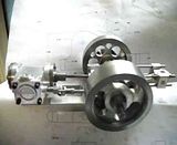
When I started this project, there was always the great possibility of failure. After all this is not a proven plan. It is an adaptation of a model and does not even follow the form or structure of the original model or even the form or structure of the simplified one cylinder version that Brian presented.

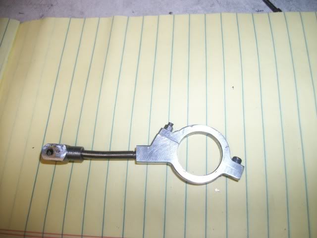
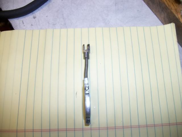
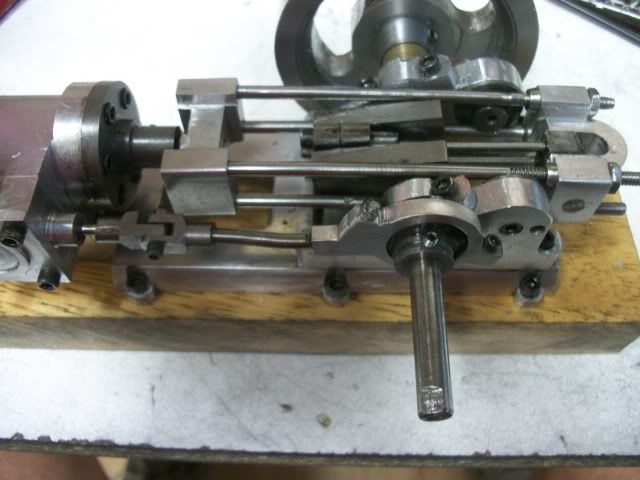
Well the possibility still exists but I have just past a major milestone. The geometry of the mechanism and the function of the reverse connecting rod are as good as I could possibly hope for, smooth, even, and amazingly friction free. No tight spots, no binding. The o-ring is not install on the piston and that will make a difference.

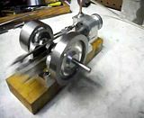
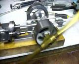
The distance between the two end braces is critical and the morning was spent fine tuning that and the piston rod length. The result is in this video.


The careful viewer will notice that the eccentric is not connected and might also notice the devining rod at the lower right hand corner that is providing the "force" but still, this is a major milestone.

Jerry 3026
 
Jerry - you amaze me... Not only the creativity but the speed that you are able to make your model.. While you have built your model I have built two parts. My hat is off to you.

This is incredible work!!!! Thank you for sharing it.

Harold
 
Very nice, Jerry. Have you patented that devining rod drive? It might be the answer to our energy crunch here in North America!!! Beautifull work!!!---Brian
 
Harold Lee said:
Jerry - you amaze me... Not only the creativity but the speed that you are able to make your model.. While you have built your model I have built two parts. My hat is off to you.

This is incredible work!!!! Thank you for sharing it.

Harold
Thanks, Harold. I'm working as fast as I can. So much to do, so little time.

Brian, if you think the devining rod is cool. check out the video at the end of this post.

I spent yesterday with the eccentric and strap. The eccentric is nothing special, just a cast iron disk with a single flange. The second flange will screw onto the face. This will let me use a one piece ecc strap. Well, not really one piece, it has a 1/8" SS rod with a plain steel pivot at one end and an aluminum circle at the other end. The inside diameter of the aluminum is shrink fitted with a thin cast iron ring to wear against the cast iron eccentric.

I fiddled with the valve adjustment and was ready for an initial test. I flipped the switch to start the compressor and no response. The compressor is in the next room so I went to check it out. IT IS GONE. MISSING. DISAPPEARED.

I called my son-in-law to see if he new where it was and he said that he had taken it out to the training center (horses) because he had some carpentry to do. I reminded him that just because he owns the compressor doesn't mean that he can use it any time he damn well pleases!!! I'm going shopping for a compressor tomorrow.

Well, I was all set for a test so that's what I did. Here is the results:


I'm satisfied.

Jerry
 
Nifty trick, with no airline running to the steamchest. Are you sure you weren't involved with the original Godzilla movie?? nice looking engine.
 
kvom said:
If you didn't have a compressor, how did you run it? ???

Kvom - I didn't say That I ran it. I said that i tested it. I hope I didn't mislead anyone. The purpose of the test was to check the operation of the valve and the only way I could think to do that was to spin it in reverse and see if I could feel air pulses in the inlet tube. I hooked it up to my little unimat with a variable speed control and it pumped air just fine so I was satisfied.

Brian - My only connection with the Godzilla movie was laughing at the visible wires and the hokey effects. Is that what you mean't?


I went to Harbor Freight and bought a 1/3 HP 3Gallon compressor for $50. It ought to be good enough for inflating balloons and blowing chips off the bench and running an occasional low pressure engine. I got it home, hooked it up an put the engine to the test.

It takes a long time to upload videos to Photobucket so After dinner, I will show the results. Honest! No tricks!

Jerry
 
The video is uploaded and ready for viewing.

I should apologize for rushing this engine to this point, it is not "finished" in any way. I just got so anxious to see it under power. I was concerned about the balance. I was concerned about the effectiveness of the guide spools and their location and would they provide the stability needed for the crank, or would the whole frame flop around at the end of the stroke. Well, now I know. It works just great. I am amazed at how well it works. In the following video, the base is just sitting on the wooden block to provide clearance for the 3" flywheel. At the hoped for slow speed operation, it just sits there. If I speed it up to about 250 rpm, it starts to slide back and forth but does not hop up and down.

here is the first run under air:


I think now that I know the design is sound, I can slow dow and pay a little more attention to completion. Once that is done, I can turn my attention to the vertical version. I look forward to that because it will let me proceed with confidence and put in place all the design refinements that I learned with this one.

Jerry 3478
 

Man, what a nice engine Jerry. As you said, smooth and well balanced.

Beautifully made, and quick too.

Congratulations!

 
WOW!!!! That was a super fast build!!!
And a very slick running engine Jerry!

Congratulations on Engine #1!!!

Can't wait for #2!

Andrew
 
Brian, Kevin, Andrew - Thanks for the kind comments. There is lots more to finish this engine and if I can stop watching it for a while, I'll get on with it.

No engine test is complete in this shop without a run with the Big Baton. With this setup, I was able to bring the speed down to 54 RPM.


Jerry
 
While waiting for some material to start the 2nd engine on this thread I decided to refine some of the parts that were hurried over in the rush to trial. You probably didn't notice the clunky over sized eccentric and eccentric strap. That is because they were carefully hidden from view and will remain hidden now that there is a new and much more presentable set. The new eccentric has been reduced from 1" diameter to .625" while retaining the .100" offset. The strap has been changed from a solid type to a split type and while I was at it I decided to try the style where the split is not at 90 degrees to the valve rod but is set at an angle, in this case a 20 degree angle.

I first noticed this angled eccentric strap when I started the American Hoist Steam Donkey (as yet un finished but getting closer to re starting). And I have seen it on other engines as well. I'm not sure what the purpose of the angled split is but I have seen it most often on engines where the components are closely arranged so I'm guessing that it is an aid to assembly and service in tight quarters.

In any case, I like the look so here it is:

refinments015.jpg


I also decided to put a little bend in the rod. This necessary because the valve and the eccentric do not line up. This could have been remedied by putting the eccentric inside the shaft bearings but I wanted to keep the engine compact and I wanted the bearings as close together as possible. I made the pivot joint with an offset but due to miscalculation, the offset is not enough, it still needs a bend.

This style of engine (over crank/back acting) brings the crankshaft closer to the cylinder so the valve linkage is also shortened. The length of rod between the pivot and the strap is only about 1 inch and the offset is only about 1/8". The rod is only 1/8" diameter so just put it in the bench vise and bend it. No problem until you try it after threading the ends. Threading concentrates the stresses and maybe eve work hardens the stainless steel so after breaking two rods in the attempt, a light went on and I annealed the rod after threading and the the bend was easy. Here it is:

refinments019.jpg


This is so much more in more in proportion to the rest of the engine that I can now show it without the flywheel on that side. It also shows off the lug feet on the base "casting".

refinments025.jpg


Now I will have to do something about the mounting.

Jerry
 
Awesome build Gerry! I like the feet and the angle split eccentric.

Nicely done! :bow:

Dave
 
Very Nice CJ, :bow:

I well remember our discussions over bending the eccentric rod on the donkey engine. ;D

Best Regards
Bob
 
Very nice Captain, I like your choice for asthetic reasons.

So fast as well - keep up the good work and the posts.

Ken
 
Maryak said:
Very Nice CJ, :bow:

I well remember our discussions over bending the eccentric rod on the donkey engine. ;D

Best Regards
Bob


As do I! :big:

Glad that's old hat now!

Dave
 
Bob, Dave, and Ken - Thanks for your support and encouragement. This has been a fun project and surprisingly easy. No real setbacks or surprises except for the extra tapped hole on the bearing stands but I'm working on a cover up for it.

COMING SOON - AT THIS LOCATION - ENGINE NUMBER TWO - THE VERTICAL!


Jerry 4265
 
Great Job Captain, some interesting design features in their woohoo1 woohoo1 woohoo1

Looking forward to No 2

Stew
 
Very nice, really enjoy watching all the extra moving mass, adds eye appeal.
 

Latest posts

Back
Top