Two New Engines

Home Model Engine Machinist Forum

Help Support Home Model Engine Machinist Forum:

This site may earn a commission from merchant affiliate links, including eBay, Amazon, and others.

Captain Jerry

Project of the Month Winner!!!
Project of the Month Winner
Joined
Dec 2, 2008
Messages
971
Reaction score
8
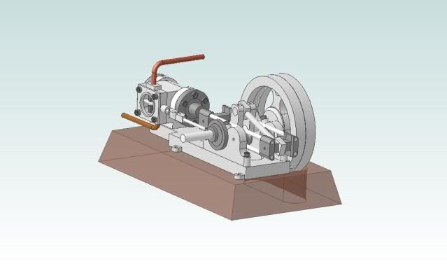
I'm starting a new project. I'm either going to build this engine:

HorizontalEngine.jpg


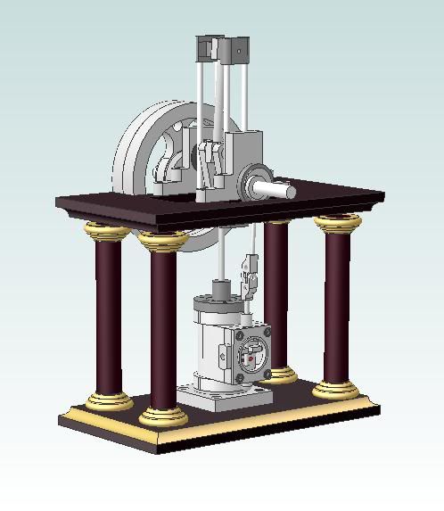
Or I'm going to build this engine:

Tableengine.jpg


Here are a animations of the two engines:

http://screencast.com/t/lBLrfnGypa

http://screencast.com/t/iegJUGdOk


The two engines are not very different so if I can keep my head straight I will try to build both engines at the same time.
I have enough of the design work done to start making chips. None of the chips will be yellow, no brass, no bronze.

Jerry

 
I like them both Captn.

Did you model that in Alibre? and then create the animation?

Nicely done!

Dave
 
Dave

I modeled and animated both engines in Alibre' but the version that I have does not include the "motion" option so I have developed a work around method of creating animations that gives good results but it does not have anyway to export the motion. The only way I have to show the animation is to use a screen capture. I use JING and SCREENCAST (both free) to capture and share the output.

These engines are inspired by the "overcrank' or back-acting mechanism as built and shown by Stew Hart and Brian Rupnow. Researching the mechanism on the web and with the help provided here by other members I find that the back-acting type was used in marine engines which were usually compound engines.

They are derived from the table engines and steeple engines of Henry Maudslay. My engines bear little resemblance to any of the predecessors except for the back-acting connecting rod. All of the examples that I could find except for Stew's wall engine used round rods instead of the flat plates so I have used round rods.

Taking a big clue from Elmer Verberg, the two engines share almost all of the mechanical part and only the structure or framework is different. The parts are bigger than Elmer's engines because I really dislike tapping #2-56 holes. Most fasteners will be #4-40 and the cylinders will be 5/8" bore and 1 1/4" stroke.

I'm itching to get started but Monday's are mostly devoted to the entertainment of Marley, my two year old GREAT granddaughter. I'm re-learning the enjoyment of peanut butter, Cherrios, and Sponge Bob Squarepants.

Jerry
 
Both great looking designs - I'll be following this thread.

Great-grandfather - how are you so computer literate - I'm only up to grandkids and I'm stuck in a time warp of DOS based Acad10 - which I still use professionally - I'm a dinosaur.

Ken
 
My vote goes to the table engine!
 
The same engines basically, one horizontal and one vertical.

I vote for the table engine, No 2!
Especially if you make the valve slide cover clear!!

Nice designs and animations!!!

Andrew
 
Captain Jerry,

That is a very intriguing design. One thing is not clear from watching the animations or looking at the model is the detail on the back crank mechanism. I assume it also functions as a crosshead to transmit the linear force from the piston to the side force for the connecting rod and crank. It is not clear how it is located. do the four rods slide on the inside crank journals?


Like Ken I am still at two year old granddaughters (two of em) and have found they much prefer Shaun The Sheep over Spongebob...

Keep us posted of your build.

Harold
 
Harold Lee said:
Captain Jerry,

That is a very intriguing design. One thing is not clear from watching the animations or looking at the model is the detail on the back crank mechanism. I assume it also functions as a crosshead to transmit the linear force from the piston to the side force for the connecting rod and crank. It is not clear how it is located. do the four rods slide on the inside crank journals?


Like Ken I am still at two year old granddaughters (two of em) and have found they much prefer Shaun The Sheep over Spongebob...

Keep us posted of your build.

Harold


Harold---It shows up best in the first animation. There is a "spool" mounted inboard of the bearing supports that guides the cross head rods.
 
Brian

Thanks for the terminology. Hereinafter it will be called a "spool" although I doubt that it will be freewheeling. I don't think I can let it roll and still have it provide the control needed without a ball bearing. The spool will be cast iron and the contact will be a sliding contact. If wear gets to be a problem, it can be loosened and rotated to present a new contact point. This is an untried method and may be subject to change if it doesn't work out.

Harold

You have zeroed in on an obvious design problem. As I said "most of the design work is done" but there are some details yet to work out. The slide assembly relies on the box structure of the four rods and the two end blocks for rigidity. I'm not sure that I can maintain that rigidity on the outboard end block and still have the con rod rotate on it. The con rod will have a typical marine style split end and bushings.

Things sometimes change between the computer and the shop which is 1/4 mile away.

Ken

I have two great grand daughters the same age but I get more time with Marley. It is an important part of my continuing education and sometimes the discoveries are as profound as they are entertaining. For example "If it doesn't have a tail, its not a monkey". [ame]http://www.youtube.com/watch?v=--szrOHtR6U[/ame]

My computer skills are self taught but I did spend some time developing computer software and formed my own company that distributed it nationally. I was old at the time.

Jerry
 
Captain Jerry said:
... snip ...
Harold

You have zeroed in on an obvious design problem. As I said "most of the design work is done" but there are some details yet to work out. The slide assembly relies on the box structure of the four rods and the two end blocks for rigidity. I'm not sure that I can maintain that rigidity on the outboard end block and still have the con rod rotate on it. The con rod will have a typical marine style split end and bushings.

Things sometimes change between the computer and the shop which is 1/4 mile away.
... snip ...

In looking a Brian's avitar, which I am assuming you were referring to in your opening statement, it looks like his back crank mechanism is supported by two slide blocks. It will be interesting to see if you get the rigidity out of your design that you hope for. I will be following your build very closely. Thanks for sharing it with us.

Harold
 
Jerry---One point.--Using a "spool" as you have shown, you will only get "point contact" with the slide mechanism. If you change that round spool to a rectangular shape, then you will get greater contact area, thus greater guidance.
 
Brian

My first thought was a square guide internally located, then two square guides externally located which would allow for adjustment. If this were to be a large scale design, I might go for external rollers. I like the appearance of the spool but it can be changed if needed.

Jerry
 
Jerry---The spool will probably work, and its a heck of a lot easier to put that radius matching the part being guided on a round turned part. The spool will have to be fixed---it cant contact both upper and lower guides AND roll. I don't think you need much more than point contact anyways, because those guides are ultimately rigidly fixed to the piston rod.
 
Can't see it being much of a problem really - the crosshead only has to keep the outer end of the piston rod travelling in a straight line.

Here I've got around a similar problem with just rods sliding in plain holes.

 
I dont think the guide spool will be a problem but that is way down the road and there are a lot of bridges to cross before that one.

Bridge One: Cylinders

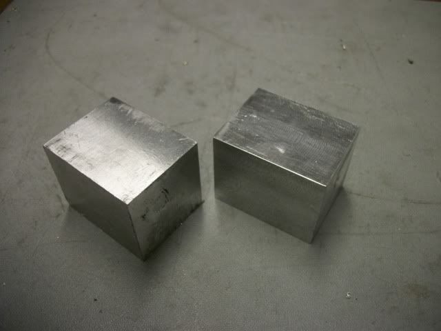
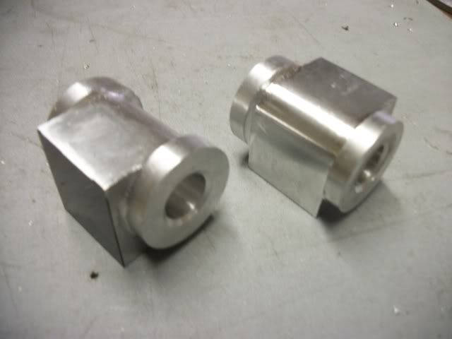
I got s little start today so here it is. Two blocks of aluminum 1 1/4" square by 1 5/8" long worked out of a larger piece using the table saw and brought to dimension on the mill.

ElmerCylinder006.jpg


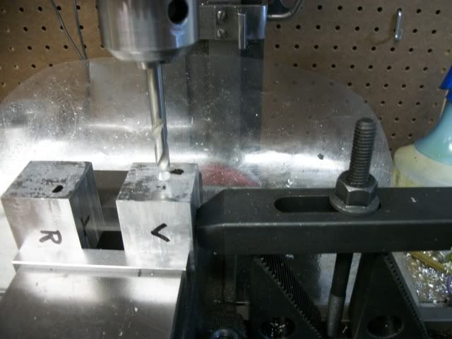
The first task is to locate the center of the bore on opposite faces. This is not the center of the face; it is .500" from each of two adjacent edges. A 15/32" hole is drilled in each face for centering in the lathe

ElmerCylinder008.jpg


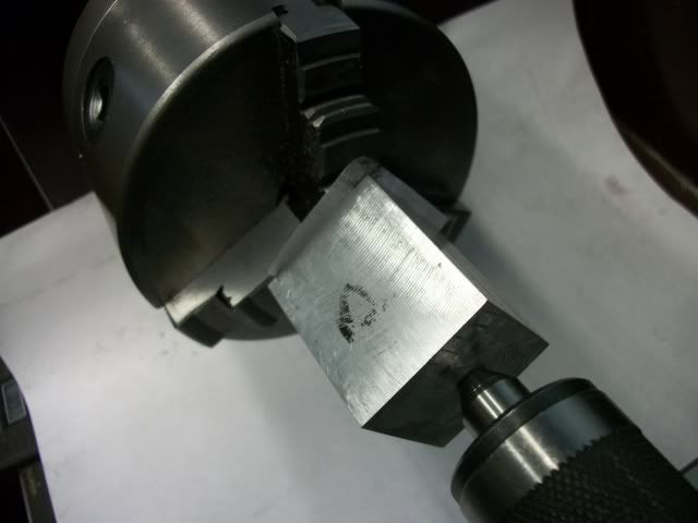
Yes, I know I could use a 4 Jaw chuck to hold the part but I haven't gotten around to ordering one for the lathe and I think my method is just as accurate and much faster. This is much like turning between centers. The headstock center that I will use is a piece of 1/4" rod on which one end has been turned a shallow taper. The rod is held in the 3 jaw and one end of the cylinder is seated on it. The tailstock with ball bearing center is brought up to the other end of the cylinder and used to force the 15/32" hole onto the tapered 1/4" rod and the jaws tightened.

When the cylinder is well seated on the rod, the 3 jaw is loosened slightly and the tailstock ram is used to drive the cylinder into full contact with the ends of the chuck jaws. The combination of the forced fit on the tapered rod and the pressure on the jaw faces may be enough to drive the workpiece but in this instance I add a little insurance by putting a piece of double sided sticky paper to the end of the workpiece before seating it on the rod.

Sticky paper is just a square of printer paper that is sprayed with 3M adhesive and stuck on the workpiece. The other side of the paper is sprayed and when pressed against the jaw ends, provides additional traction. I have seen double sided carpet tape used for the same purpose but the paper is more stable than the cloth tape and is much easier to clean since I control how much adhesive to use.

Here is the piece in the lathe ready to turn the first flange:

ElmerCylinder009.jpg


Now to turn the flange without that anoying "THUMP-THUMP-THUMP" I take the biggest bite that I can. You can use HSS but I have come to rely on cheap brazed carbide bits that I have honed to a super sharp, thumbnail scraping, edge using a cheap $1 diamond wheel in my mini grinder. The brazed carbide chip limits the depth of cut to about 3/8" which sounds like a huge cut, but my 9x20 lathe has plenty of power to handle this cut and I don't think the smaller mini lathes would have a problem with it either.

Why so deep? After a lot of experimentation, I believe that the magnitude of the "THUMP" is not so much a function of the depth of cut but is much more related to the amount of time that the bit is not in contact with the cut. If you only take a small cut, the bit will be in contact 10% and free of contact 90% of the time. As you get closer to a full round cut, the contact percentage increases until it is 100% and the "THUMP" decreases proportionally until it is gone. Taking the deepest possible cut results in almost no "THUMP" and you get to full round in only two passes. Don't take my word for it, watch the following video.


The job here is to turn a 1" diameter flange, 1/4" long on each end. To get the second end just reverse the work piece and repeat. Now, wasn't that easy?

Tomorrow, I'll try to get to profiling the rest of the cylinder and the valve ports.

Jerry
 
Cylinders continued.

I got a little more done yesterday but I was falling asleep at the computer while posting last night so here is the rest of it. I hope it doesn't put you to sleep.

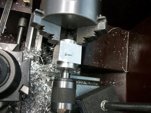
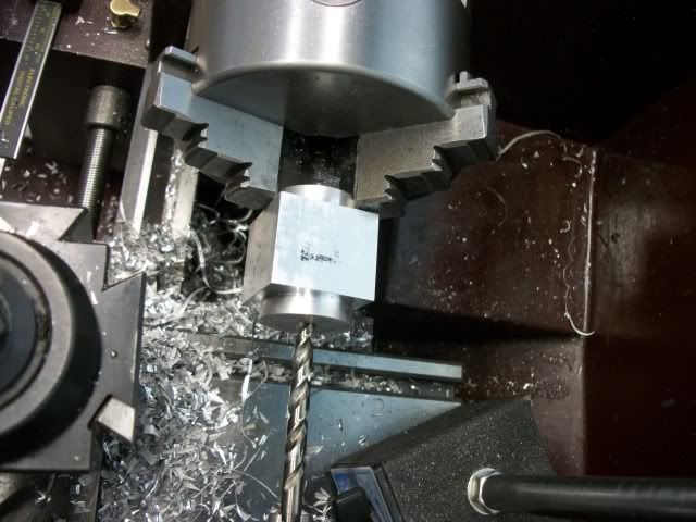
After the two flanges are turned, I grabbed one flange with the 3 jaw (loosely) and used the tailstock center to center the bore. I did set up an indicator to verify (you can see the mag base in the picture) and it was dead on. I then opened up the bore with a 1/4" bit followed by a 3/8" and then a 1/2" bit.

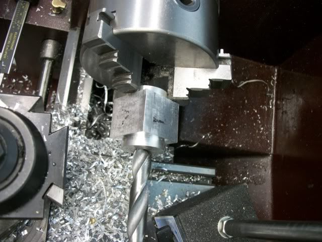
This next step is a modification of the method that Brian showed on his "Overcrank" thread. I mounted a 5/8" bit and drilled to a very shallow depth, just deep enough for the corners of the flutes to penetrate the face. As Brian pointed out, if the bore is opened up to the full 5/8 diameter, you risk having the small drill bit wander into the bore while drilling the slanted steam passage. By drilling the 5/8' to a very shallow depth, it is easier to locate the starting point for the steam passage but you still have plenty of metal to prevent problems of starting and wandering.

Centered, ready to drill
ElmerCylinder016.jpg


Drilling 1/4"
ElmerCylinder017.jpg


After the 3/8" and the 1/2" drill its ready for the shallow 5/8" bit
ElmerCylinder019.jpg


Ready for the mill
ElmerCylinder020.jpg


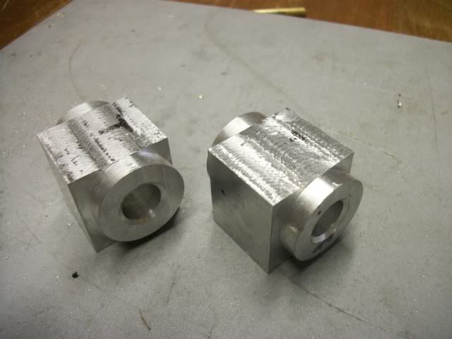
I got so involved with the process that I forgot to take pictures but the cylinders were profiled in the mill by resting the flanges on the vise jaws and repeated milling passes followed by a small angular rotation through a total of 90 degrees and then touched up with a file to remove the ridges.

ElmerCylinder021.jpg


Now ready for the valve face and the steam passages. The next time I do this, I will drill and mill the valve before profiling the cylinders so I have a better grip in the vise. I still have one flat face that is 90 deg from the valve face so I can put that against the fixed jaw in the vise and slip a little packing between the flanges to keep the moving jaw from scarring them.

This post is long enough, and I've got some mowing to do. Florida grass is still growing. Next up will be the valves and if there is any interest, I'll show how I used Dockstaders great Zuener Diagram simulation to calculate the dimension. Its a lot easier than it sounds.

Jerry 628
 
Captain Jerry said:
This post is long enough, and I've got some mowing to do. Florida grass is still growing. Next up will be the valves and if there is any interest, I'll show how I used Dockstaders great Zuener Diagram simulation to calculate the dimension. Its a lot easier than it sounds.

Jerry
Jerry:

Looking good, and definitely some interest here to see how that diagram works. Damned grass is still growing here in
Montreal as well.

cheers, Joe
 
Jerry---Even in Canader, the grass is still growing. Your progress looks very good, and I too will be interested in your diagram.---Brian
 
Captain Jerry said:
if there is any interest, I'll show how I used Dockstaders great Zuener Diagram simulation to calculate the dimension. Its a lot easier than it sounds.

Jerry,
I am always interested in valve gear discussions. I know how to construct a Zuener Diagram and I have used the Dockstader module but I do not find it nearly as handy as the Bilgram diagram which will give exactly the same answer.

The way to see the curves for this engine is to use the slip eccentric program. I know that you are not using slip eccentric but the curves will look the same as a nonreversing engine with the same port design and cylinder dimensions.

Dan
 

Latest posts

Back
Top