Two New Engines

Home Model Engine Machinist Forum

Help Support Home Model Engine Machinist Forum:

This site may earn a commission from merchant affiliate links, including eBay, Amazon, and others.
Brian Rupnow said:
Jerry--for what you are doing, I would leave the cylinder wall shiny and bright. If you de-glaze it, the de-glazing stones will crosshatch a microscopic ridge pattern which will reduce the o-ring life. You want that de-glazed surface to help wear in the sliding surface of a metal ring. When using a rubber or nitrile o-ring, you don't want to do that.---Brian

Brian, that is what I thought but a second opinion is reassuring.

robcas631 said:
They are both terrific and aesthetically pleasing. The design is amazing. Everyone here seems to come up with a design that is not only functional but revolutionary in design.

Thanks, Robcas631, that's what I was aiming for.

danstir said:
Thanks for the explanation of lapping the cylinder. I have read about it but your pictures helped make more sense of it. The simple oscillator engines I've built so far didn't need it, but I'm hoping to start building more complex engines.

There are other, and perhaps more precise methods, but if the starting surface is straight and even, this is a quick and cheap method. Brasso works well on softer metals and I mix it with light oil for the final few passes. If the starting finish is uneven or deeply ridged, a reamer might be needed first.

Jerry
 
Good news...bad news...good news.

First good news...I have 3 days of nothing but shop time. My wife has gone with my daughter to visit my granddaughter at school. All the grass is mowed. All the horses have gone to the training center. Nothing to do but play in the shed. I ought to get a lot done!

Bad news... I left my camera in her car so it has gone to Tennessee with her. I could wait for her to get back or I could just plow ahead and tell you about it without pictures.

Good news... I did get a lot done today. I decided to plow ahead. I think that I will concentrate on the horizontal version and when I get the camera back I'll resume the vertical version.

Today I got the cylinder and valve complete. I started to work on the crankshaft and connecting rod. The crankshaft is an ordinary built up design using 1/4" TGP steel for shaft and journal held together with locktite and pins. The webs are from 1/4" mild steel. To be absolutely sure that the shaft and journal holes are parallel, the webs were glued together with locktite and drilled and reamed as a unit. The mating faces were marked before they were glued together so that they can be assembled right.

After they were drilled and separated, I faced the inner faces of the web, leaving a boss at the journal hole. This was done by putting the ball bearing tailstock center into the journal hole and forcing the web against the chuck jaw face as I have done on other parts in this build. I know this method seems odd to many people but it is quick, accurate, easy and safe. Three very light passes and I nice .030" boss , 1/2" dia. was standing proud on each face.

For this facing cut, I start as close to the center as I can get the tool without hitting the center and feed outward. This is a long interrupted cut so light cuts are a must. At one point, I got a little overzealous with the feed and the bit dug in and stopped the rotation of the part. I just eased off the cut, checked the pressure on the tailstock ram and continued. Nothing hurt, no underwear change.

If the part had been on a mandrel or in a chuck there is a good chance that something would have got bent or the part would have been ruined. I like this method of work holding and use it a lot. Crankshaft will be finished tomorrow.

On to the con rod and frame. The outer end of the frame has been a little fuzzy in my design, I wasn't quite sure how it was going to work. If I used a fixed shaft pin, I would have to build a split bushing and rod end. If I used a removeable pin, and a solid rod end with bushing, I would have to add a second connector bar for rigidity.

Here is my solution:

Tabletopendguidebar.jpg


tableguidewithpistonandrod.jpg


It will have a removable 3/16" pivot pin and a solid aluminum con rod end with a cast iron bushing.

The frame is very rigid. I had some worries. The rods are 1/8" SS threaded #6-32 in tapped holes in the piston end brace. The outer end of the rods will also be threaded but the brace will be drilled for clearance and secured with nuts so that it can fit over the crankshaft at assembly. The space for the nuts is a little tight. I think I will order some model scale nuts for a better appearance.

It has been a busy and productive day. Sorry about the lack of pics but I will show these parts and procedures when I get to the vertical model.

Jerry 1829
 
Jerry---I use your method of turning all the time, and it works good. It even works better if you buy a roll of carpet tape. (thats the kind with "sticky" on both sides.) and put a layer between the part you are turning and the chuck jaw face. It lets you take much deeper cuts without stalling the part. The tape is vry easily removed afterwards.---Brian
 
Brian Rupnow said:
Jerry---I use your method of turning all the time, and it works good. It even works better if you buy a roll of carpet tape. (thats the kind with "sticky" on both sides.) and put a layer between the part you are turning and the chuck jaw face. It lets you take much deeper cuts without stalling the part. The tape is vry easily removed afterwards.---Brian

Brian - I have used the double sided tape but I can't always find it. Its here somewhere. For very small parts it is easier without the sticky stuff so I go bare or maybe a piece of paper, sometimes with spray adhesive on the paper.


I had another productive day in the shop. Finished the crankshaft. I couldn't find a soft nail and a drill bit that were close enough but I had a piece of 3/32" SS rod and my matching bit is nice and sharp and the hole is a tight push fit so that's what I used.

I made several connecting rods before getting one that I liked. I was trying for a very light rod since there is no counterweight on the crank webs. This is a very short rod and a flat bar just looked heavy. Turned rods, even with fish bellies didn't look right either. I don't know of any precedent for what I came up with but since this is not a historical model, so I feel free to take some liberties. The structure is two parallel 3/32" SS rods with cast iron ends, split on the big end, plain on the little end. It is light and strong and carries the parallel rod theme from the guide frame.

TWOBARCONROD.jpg


GuideRodandCrank.jpg


Sorry about the lack of pics but models are better than nothing.

Jerry 1979
 
Good news, my wife is home and my camera is with her. She got home late this afternoon so I had time to get some pics of the project as it stands and some of the parts that are finished.

Here is the slide frame top end. The wrist pin is 3/16 TGP shaft rod freen in the brace and held in position with set screws at both ends.

SANSBRASS011.jpg


Here it is in a trial fit on the guide rod frame.

SANSBRASS013.jpg


Here the two bar con rod is fitted to the wrist pin and the crank shaft.

SANSBRASS026.jpg


And this is the whole guide frame with crankshaft and con rod as it will be oriented in the vertical engine.

SANSBRASS028.jpg


Before I can fit the horizontal engine I need the base and the bearing stands. I need to make some minor changes but I'll post the design before I quit tonight.

Tomorrow will be a workout with the tablesaw.

Jerry
 
This is the base that I will work on tomorrow. I want to try to achieve the appearance of a cast iron base common on small engines. A big part of that look is the sloped perimeter from the draft needed to pull the pattern from the mold and the lugs to bolt the frame to the floor. The angle of slope on this model is 10 degrees which might be a little excessive for draft but I'm not trying to be subtle. A pattern maker would use a table saw to get this slope on the pattern so thats what I'm going to use. It would be fairly simple if the base were just a rectangle but the narrowed section under the cylinder presents a special problem in the corner where the adjoining faces meet.

The elongated holes are needed to clear the crank. I can't think of a method to slope these interior edges so they will be square but I don't think it will show.

The feet are just separate parts, fitted into milled slots.

basewithfeetb.jpg


Jerry 2205
 
Cap'n Jerry:

If this part is being made out of aluminum, you could do a finish pass on the edges of the openings
with a vertical panel-raising router bit.... could use the same bit for the outside as well so that the
angles match, would take some careful filing in the corners ;D

Joe
 
joe d said:
Cap'n Jerry:

If this part is being made out of aluminum, you could do a finish pass on the edges of the openings
with a vertical panel-raising router bit.... could use the same bit for the outside as well so that the
angles match, would take some careful filing in the corners ;D

Joe

Joe - I did a search for that kind of bit but didn't find anything usefull. Can you point me to something? I used round ended slots in the design that can be drilled with a 5/8" bit but I have been thinking of changing that to square ended slots that might be more authentic and which I can slope with a file. I will probably leave the holes until after I have the bearing stands installed to be sure of location to clear the crank.
 
Cap'n Jerry,
Looking good.
Tapered endmills are available for mold and pattern making. I have a selection that I have acquired over the years as needed and use regularly.
Many tooling supplier have them. Here is a link to Enco's page on them.

http://www.use-enco.com/CGI/INPDFF?PMPAGE=157&PARTPG=INLMK32

Gail in NM
 
Jerry

Lee Valley Tools is where I get most of my router bits, but I see Gail has posted a source for the right tools!

Joe
 
GailInNM said:
Cap'n Jerry,
Looking good.
Tapered endmills are available for mold and pattern making. I have a selection that I have acquired over the years as needed and use regularly.
Many tooling supplier have them. Here is a link to Enco's page on them.

http://www.use-enco.com/CGI/INPDFF?PMPAGE=157&PARTPG=INLMK32

Gail in NM

Thanks Gail, that would be the way to go if I thought I would last log enough to get a fair return on investment. I'm now thinking I'll mill it square and slope it with a file.

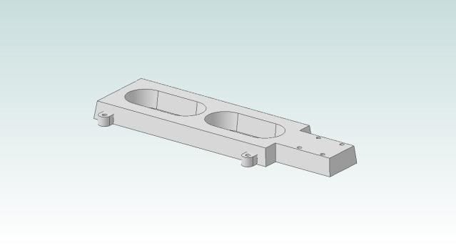
Here is what I did today.

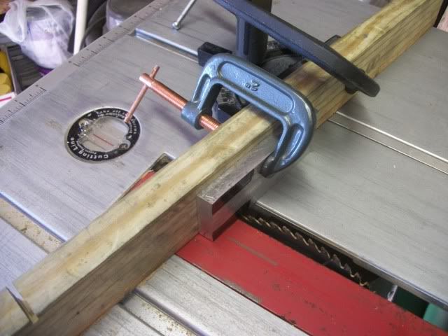
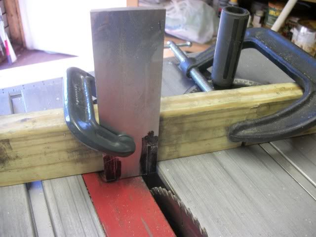
Starting with a big chunk of aluminum 1.68" x 2.25" x 12" I'll rip a piece .4" x 1.68' on the saw. Using a 9" 60 tooth carbide tipped blade. I can't get the full cut in one pass. I have found that it is better to do it with 5 cuts. The first cut is about 1/4 of the thickness. Two cuts, one on each face, keeping the same face against the rip fence. The depth o cut is the set to just under 1/2 of the thickness and a cut is made on each face. The blade is raised enough to complete the cut and one last pass separates the parts. Doing it this way keeps the part from getting too hot to touch. You must be sure that your rip fence is parallel to the blade to eliminate binding and friction.

015.jpg


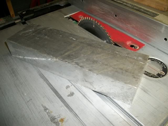
With the slab cut to thickness, the blade is tilted to 10 degrees and the blank is cut to length. I cut it slightly over finished length. leaving just enough for filing to length. Next time, I would save this step for last, after cutting the shoulders for the narrow section. That would leave me room to make correction if I foul up the shoulder.

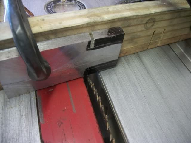
To cut the shoulder, the depth is set to cut to the wide part of the base and the miter guage is angled to 10 degrees. I clamp the part to a waste fence and the clamp the fence to the miter guage.

021.jpg


Cutting to the mark by eye is not that hard.

022.jpg


The mitre guage is swung to 10 degrees the other way and the second shoulder is cut to the same depth.

023.jpg


The blade is vertical for all of these cuts.

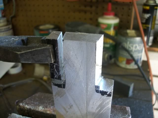
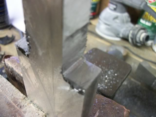
Now I'm ready to free the waste. Leaving the miter gauge set to 10 degrees. The part is stood on end and the blade depth is set to the length of the shoulder. Cut one shoulder, swing the miter gauge the other way and make the other cut.

SANSBRASS017.jpg


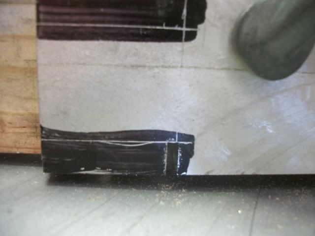
These last two cuts do not free the waste. The waste is still attached by a small amount of material in the corner. Break it free with pliers.

025.jpg


this is what is left in the corner.

027.jpg


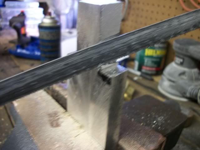
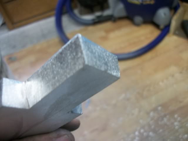
Clean it up with a hacksaw:

028.jpg


and a file

029.jpg


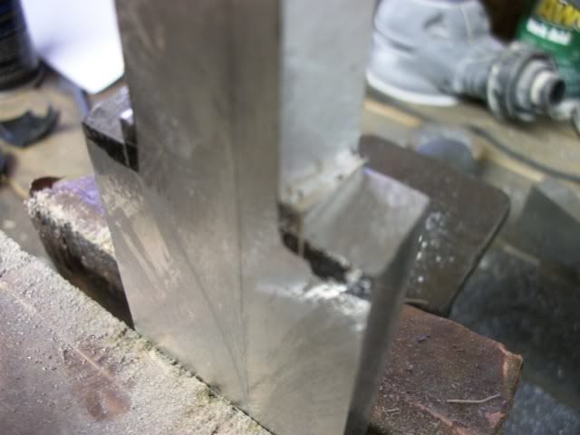
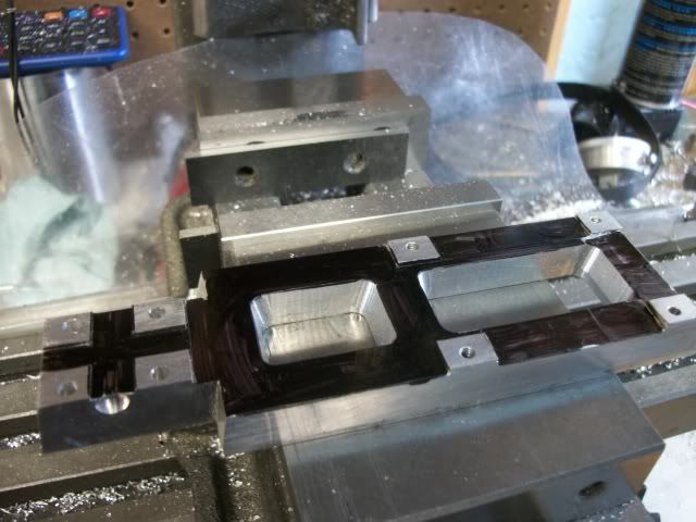
and this is the result:

030.jpg


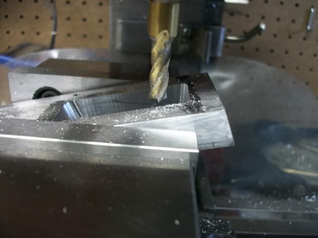
Now you can tilt the blade to 10 degrees and cut the long sides and the ends.

At this point, my eyes spotted my random orbit sander on the bench with a 100 grit disc. I wonder if that will give the appearance of a casting from a sand mold? I tried it. Maybe, I'll experiment with this later.

031.jpg


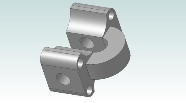
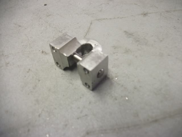
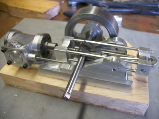
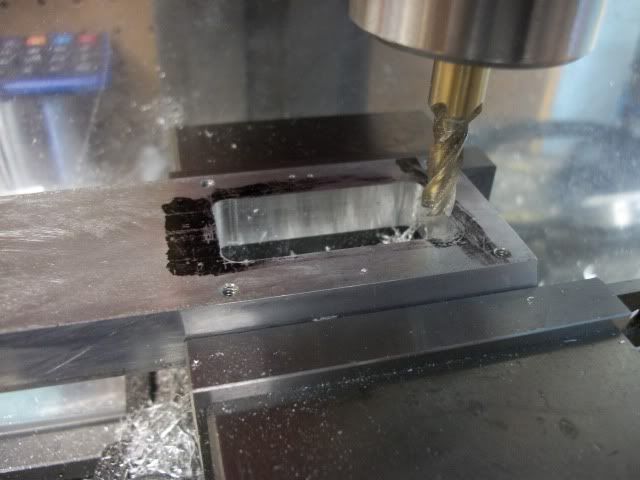
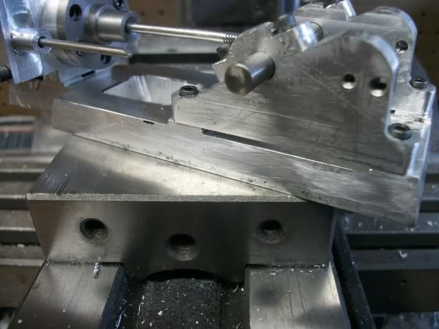
I then turned my attention to the two bearing stands. Nothing really spectacular here. I milled a piece of 3/8 thick plate to .300" thick, cut out two appropriate sized pieces, screwed them together through the center of the guide spool and profiled them on the mill.

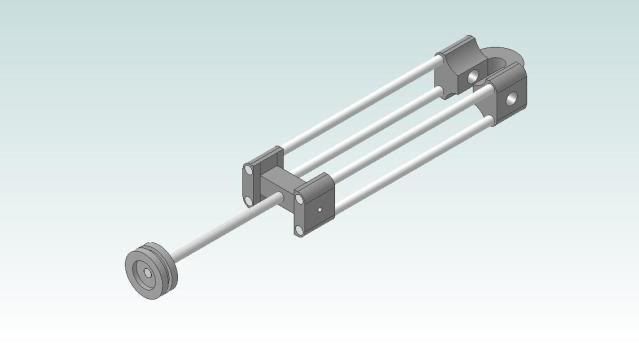
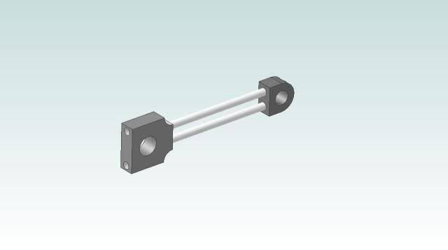
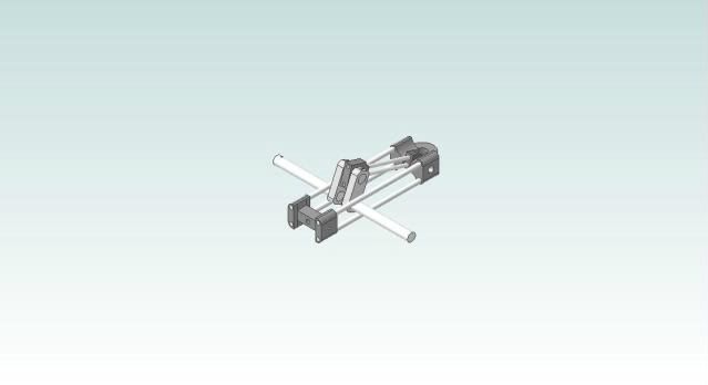
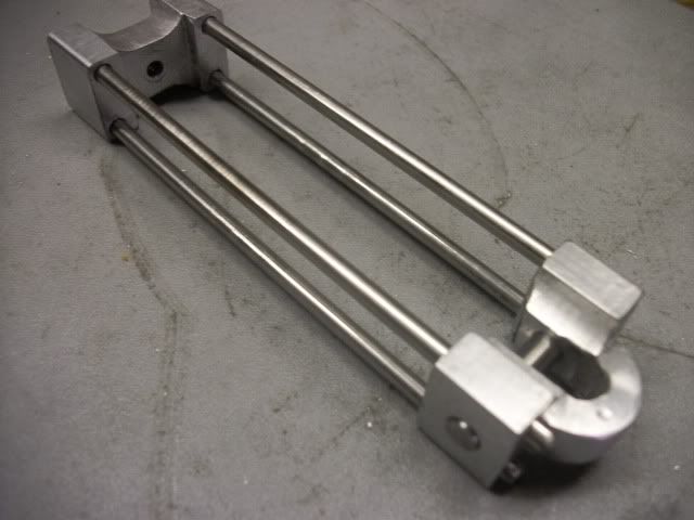
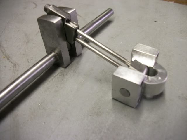
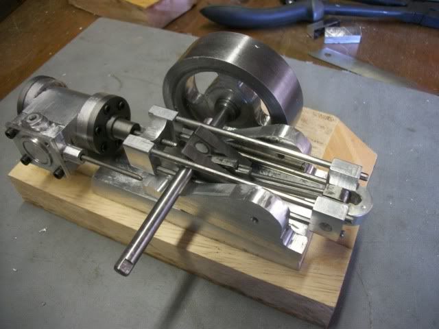
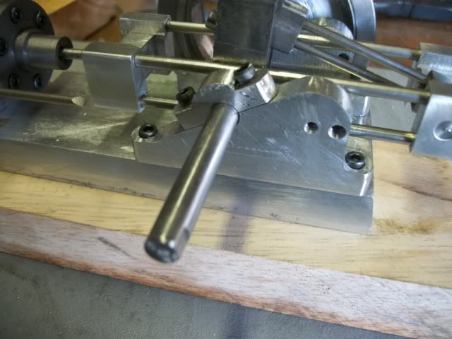
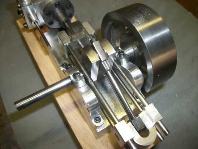
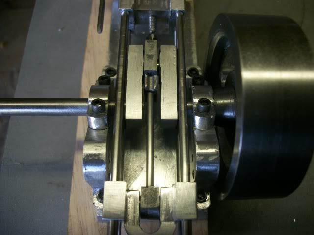
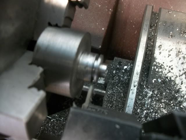
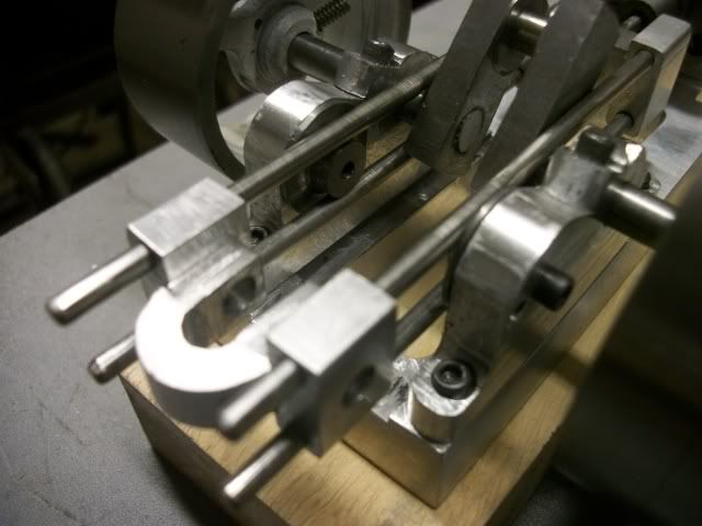
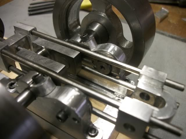
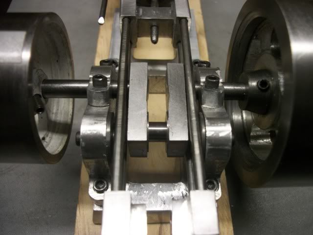
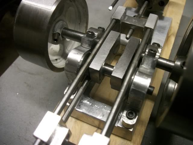
Then the whistle blew and it was time to clean up and go home. I got a few mock assembly pics before I quit.

037.jpg


and

035.jpg


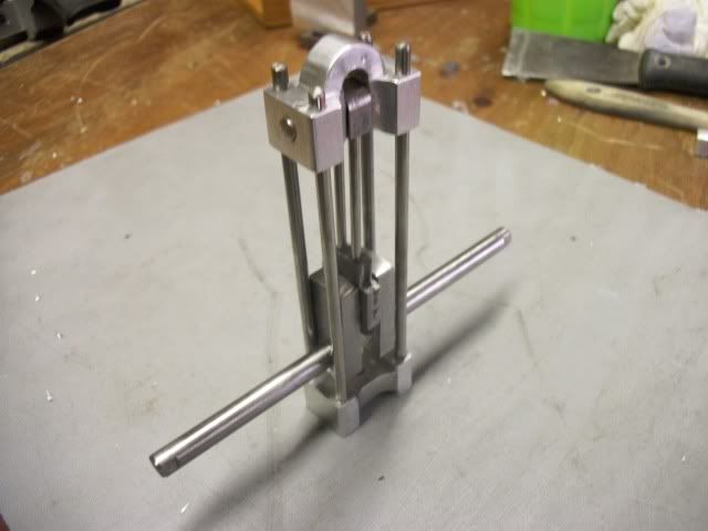
Its shaping up. Lots more to do but its beginning to look like the plan.

I'm beginning to get concerned about all of the unbalanced reciprocating weight without any counterweights on the crankshaft. Stew or Brian, did you find that to be a problem?

Jerry


If you are comfortable with a table saw, thus is simple and straight forward. I have spent many hours with a table saw, making just this kind of special cuts (on wood) while under the watchfull eye of hundreds of spectators at woodworking demonstrations. I worked for both Shopsmith and DeWalt in my youth and have owned a number of table saws. This work was done on a cheap Hitachi portable saw. One of these days, I may get around to building a sliding table jig for this kind of cut but for now, clamps and a waste fence work just fine.

Aluminum can be cut on a table saw as easily as most wood and much easier than some. If you want to try something difficult, try this on a piece of gummy Georgia yellow pine.

If you are not as comfortable with a table saw, try it first on a piece of scrap wood.

That chunk of aluminum is from my local scrap yard. Big chunks of top quality aluminum at great prices. If you are having a hard time finding a big chunk of aluminum for an engine block or some special project., give me a PM and maybe I can help.

Jerry 2472
 
Jerry---I didn't noticie the lack of countetrewight as being a problem, but these are a slow running engine. What you are doing is looking very good.---Brian
 

Great progress Jerry. It looks great!
 
I made some more progress today but it was difficult what with stopping every few minutes to kick myself in the butt for the stupid mistake I made yesterday. When I stopped yesterday, I had the bearing stands profiled and this morning I mounted the bearing caps and drilled the crankshaft hole on the line between the stand and the cap. This is not a finished bore. It is just going to be used for checking relative position and for locating the stands on the base. Later the bore will be enlarged and fitted with cast iron bushings.

The butt kicking is because, I misread or mis set the radius of the curve where the guide spools will mount. This is critical because the 30 degree slope on the face is tangent to this curve. Now when I positioned the crankshaft on the slope, it is spaced too far from the center of the guide spool. Kick butt. I can't just reduce the radius and re mill the slope because the bearing caps and the shoft hole won't work out. The only solution is to reposition the guide spool in correct relationship to the shaft bore and mill a new curve tangent to the slope. Got this worked out and here is the result

BearingStands001.jpg


The only evidence of the mistake is the large tapped hole to the right of the hole at the center of the radius. I will call this a mounting location for an as yet unreleased future option.

I spent a little time reprofiling the brace blocks at both ends of the slide. They just looked a little too heavy.

BearingStands004.jpg


The bearing stands are now positioned and mounted on the base so now I can mark out the clearance holes and get that job done tomorrow. Then I'll turn my attention to the guide spools.

A view from the top shows how tight the clearances are but it is going together nicely.

BearingStands008.jpg


Jerry
 
Wow Jerry you've certainly got a move on with this build, its looking real well.

As for the recipricating forces with my twin cylinder they were no problems at all, and Brians single ran well so i don't think you should have any problems.

I think you're going to have a real nice running engine real soon.

Stew
 
sbwhart said:
Wow Jerry you've certainly got a move on with this build, its looking real well.

Stew

Moving pretty quick for an old guy. Would you believe, this is the first single cylinder engine I ever built? It goes a lot quicker without the extra cylinders and all that goes with them.

I got the clearances marked out an opened up the base to clear the crank:

baseandguides005.jpg


I decided to taper the ends of the holes. I'll leave the sides straight. There is almost no way that will be seen through the works:

baseandguides006.jpg


It started to look more like a casting and then I realized that if this were a casting, the whole top surface would not be flat. There would have been raised bosses for the mounts so that only those small areas would need to be surfaced, so I milled away about 1/16" of the top except where the cylinder and the bearing stands are bolted. This didn't show up well in the pics so I painted the dropped surfaces with magic marker so you can see it.

baseandguides007.jpg


I decided to use four holes to mount the cylinder. Less chance of breaking into the bore.

Cylinder and bearing stands mounted on the raised bosses:

baseandguides008.jpg


I turned up the guide spools from cast iron and parted off:

baseandguides009.jpg


Sorry for the fuzzy pic. I'm not so hot with a camera. The cylindrical part of the spool is straight with no radius. It will limit vertical movement. Lateral movement is limited by the wide shoulder which has a nearly flat conical face so there should only be line contact with the rods. Here they are mounted inside the frame:

baseandguides011.jpg


All clear, top-bottom-sides:

baseandguides010.jpg

baseandguides012.jpg

baseandguides014.jpg


Friday night...Pizza and Beer! Cheers!! 2900

Jerry
 
Looks good Jerry. I kind of thought that this might be your first single cylinder build. I followed your "donkey" thread with interest, and then a bunch of swashplate type engines. This is looking really good.
 

Latest posts

Back
Top