Topsy Turvy Hit & Miss Engine Build

Home Model Engine Machinist Forum

Help Support Home Model Engine Machinist Forum:

This site may earn a commission from merchant affiliate links, including eBay, Amazon, and others.
Pete,

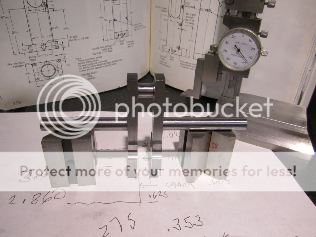
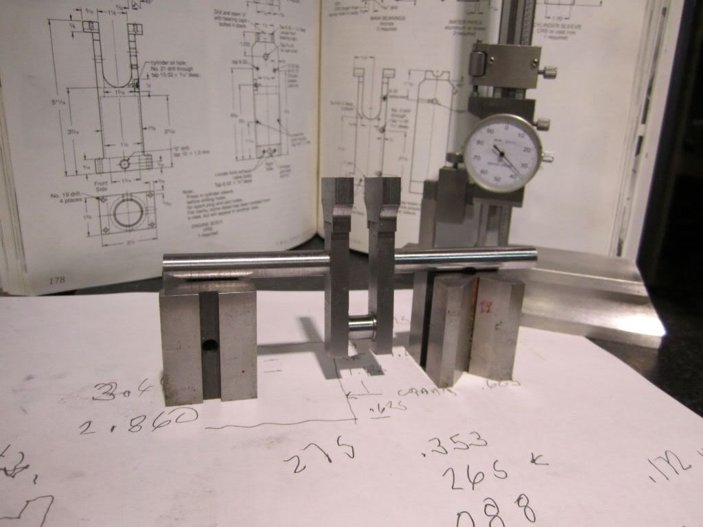
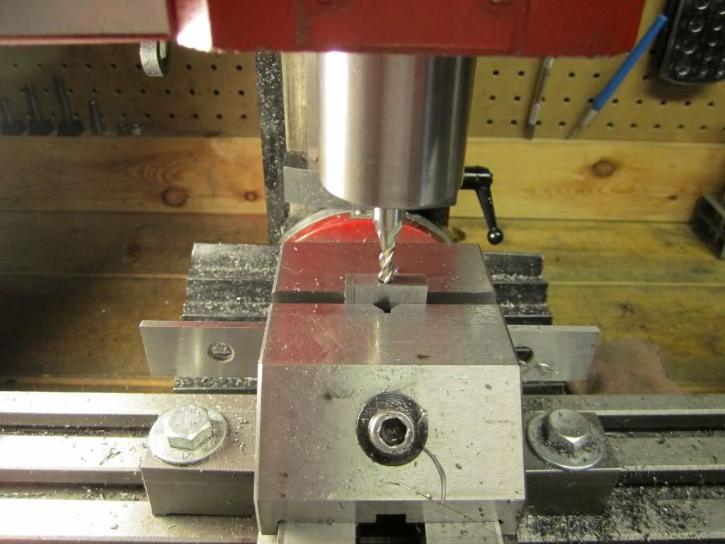
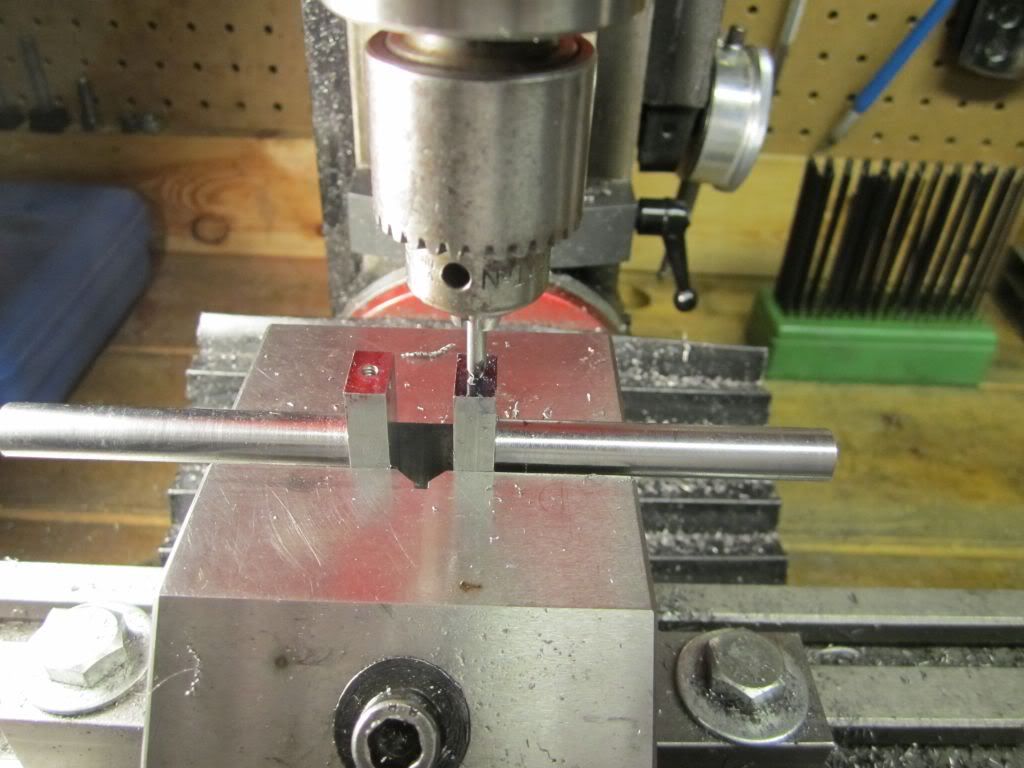
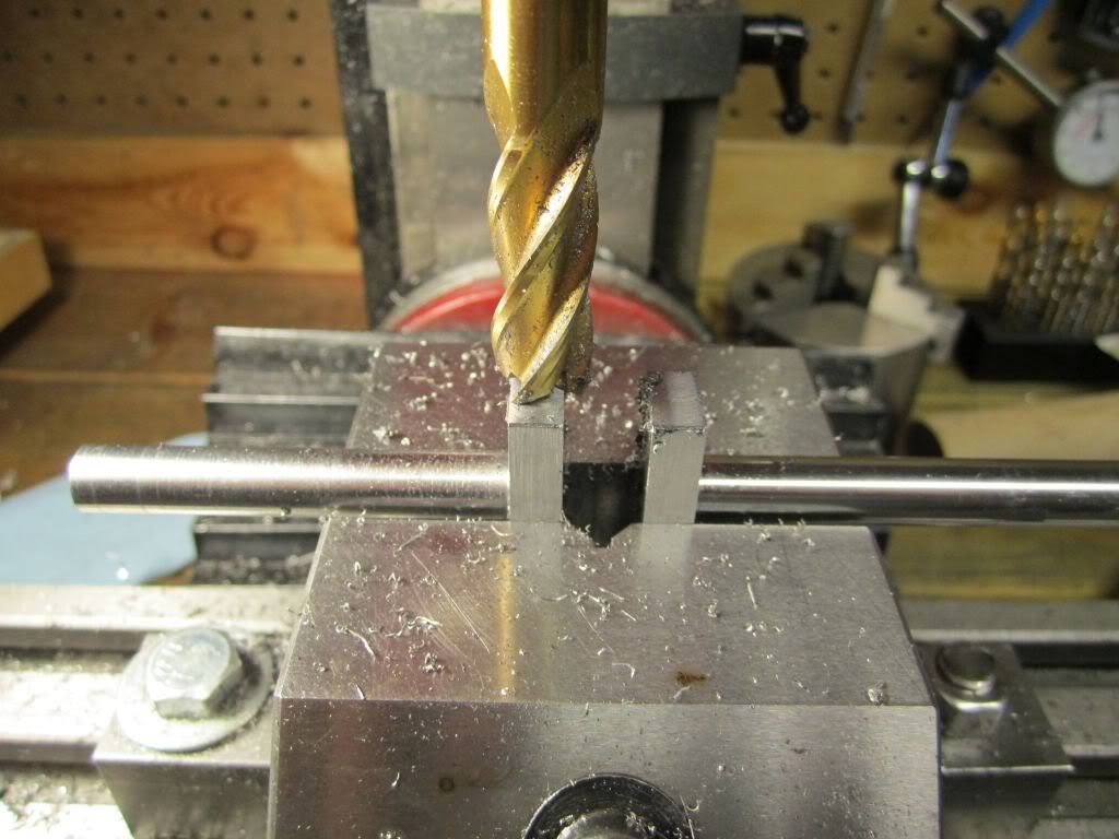
Thank you for your comments.. You are correct... I have had a center punch move the center drill a few thousandths.. On my crankshaft I did the layout and did not use the center punch. I'll do that in the future and just use the layout line to confirm the location but not try to draw the center drill to it.

I completely agree with you on Philip and Rudy. They are my favorites as well. I have built Rudy's marine compound, his walking beam, and about 90% complete on his steam tractor. Regarding Philip, I have built three Odds & Ends and now this. I have all of their "Shop Wisdom" books as well as the "Steam & Stirling" books from the 70s and 80s which had some of Philip's early works in it.

I have posted youtube videos of all of them... Search on hlee1946 and my videos should come up...

Thanks Again for your input and help.

Harold
 
Harold,
I even tried to delete the marking out step but every once in awhile a mistake could and would creep in. Probably people more experienced than myself can do it, But for now the marking out is a definate nessesity for me just as a double check. Before DRO's and CNC became commanplace Moore jig borers and jig grinders used much the same methods as You and I do. They actuly had wells cast into the machine at the dial indicator locations and also used removable and very precise rods much like micrometer setting rods to extend the reach of the dial indicators.

Pete
 
Today I completed the turning operation on the crankshaft. I was very pleased with the results and then got in a rush and made an UH OH... But I get ahead of myself...
After turning the connecting rod journal I sawed off the centers, put a 3/8 bolt and nut on it and started turning the rest of it. Notice the left crank web. I started sawing and was concerned that it would be too close to the finished dimension if the saw moved. I moved it over and restarted the cut. When I finished the webs to final dimensions everything was ok..

TopsyTurvy-Sept20-18.jpg


The first thing I did was turn both ends round and then started turning them to size... Here is a question... Should I have loosened the bolt holding the web before I made my finish cut? My thought was to relieve any stress that had built up by removing all of the metal. Even though this is HRS I was wondering if it would make a difference.

TopsyTurvy-Sept20-21.jpg


After turning it to .377 ( .0025 over ) I completed it by hand with a file and two grits of cloth.

TopsyTurvy-Sept20-23.jpg


At this point I wanted to clean it up for pictures so I put it on the belt sander to remove the scale on the crank throws..... RUH ROH.. It did that and in the process I nicked one of the shafts.

TopsyTurvySept21-1.jpg


Look on the left shaft and you can see the flat spot...

TopsyTurvySept21-2.jpg


At this point I was going into failure mode after two days of work but I realized I needed to make a keyway cut for the flywheel and this is a perfect place for it. So I climbed back on my emotional roller coaster and continued... I then milled off the edges of the crank webs on the shaft end for the counter weights.

TopsyTurvySept21-6.jpg


My next step is to make the two crank counter weights and bolt them on...


looking good harold ;D ;D

i think i have the plans to build this engine and it is on my long long list of engines to build.
i will be copying these picture and words into a file so that if and when i get to building this engine
i can reference your work to help out my build.

thanks again :)

chuck
 
Chuck - Thank you for your encouragement. I was very intimidated by this project for two reasons. The body of the engine is really sticking out on the lathe when the "guts" are bored out. I found out I had to go very carefully and take small cuts. I used a 1/2 boring bar and had to go slow. The crankshaft was the other reason. The two inch throw meant the tools fir cutting the connecting rod journal is really hanging out as well. If I had a old South Bend or a Logan I would not be concerned at all. The 9X20 hobby lathe is much lighter yet it can be coaxed into doing the job. Moving forward, I feel much more confident since the remainder of it is essentially more of what I did on the Odds & Ends engines. I'm sure there are some issues lurking in some of the darker corners ahead but I'll deal with those as they come up....

Thanks Again,

Harold
 
Hello Harold,
Nice engine that Topsy Turvy. I made one myself. I work metric, so I took 32 mm for the inch. So it became some 25% bigger. It runs very well.
By the way, you said that you turned a diameter 0.0025 over and finished with a file and cloth. Why is that???
I prefer to use the sharp lathe tool.
Then you get a cylindrical diameter! now you are not sure of that. Just an opinion.

Nemt
 
Hello Nemt,

When I made my Odds & Ends engines I found that the diameter of the shafts would vary by .0015 and produces a finish that had a wavy pattern in it. I have my lathe mounted on a wooden bench and assumed it was a combination of the mounting and the limitations of the lathe. I have replaced the headstock bearing with $80 P6 bearings. Looked for gear train noise and cannot determine the source of the problem. I even replaced the motor thinking perhaps it was introducing a harmonic due to balance or a shorted winding. Regarding the taper, I have purchased a ground test bar ( $280) and have a precision level ( $65 )but have not been able to get repeatability over the length of the shaft. I have adjusted the tailstock multiple times. When I bored out the body of the engine ( no turning between centers) I get diameters that vary less than .0002. I have come to the opinion that I have a cheap Chinese lathe that was built on a Monday morning and have come to accept the limitations and developed workarounds. In the past I owned a 12 inch Atlas lathe and know that this is not normal but at this point I do not know how to fix it other than turn oversize and finish by hand. Any ideas or advice would be appreciated.

Thank you for your comments.

Harold
 
Nemt,

After reading my previous post and giving it some further thought I just wanted to add a few comments. At the beginning of this thread I said I was not a machinist by trade. I have been a hobbyist for a number of years and my formal training was in my metal shop class in my junior and senior years of high school in the early 60s. That being said, nowhere in my post did I take any of the responsibility for some of the issues; choosing to put it all on the machine. I know there are other factors like tool bits and how they are ground/honed. I am sure they add to some of the issues as well. I have always heard that anyone can make good parts on a good machine and it takes a machinist to make good parts on a poor machine. I think when we hit our limitations in a particular approach we look for ways to get around them...

Thanks again for your comments.


Harold
 
Harold,
Since I don't want to to post unnecessary information in this post maybe if you started a new thread with a bit more information about your lathes problems we could collectively figure out and solve the problems?

Pete
 

Harold,
In my experience, "sneaking up" on a dimension with files and such is perfectly acceptable.
It may not be the most efficient, but if you are happy with the part it's fine.

Regards,
Mike
 
Pete - I am interested in discussing my lathe issues. Where would be a good place to start a thread?

Mike - In my previous build of my three Odds & Ends engines I did it the way I did this one. While it worked for me, if there is a better way to do it I would sure like to understand it. I think most of us are here to not only share our work but also to have people share their expertese with us. I am certainly open for suggestions/ constructive criticisms.
Thank you.

Harold
 
Harold,
Probably in the "Tools" forum.

Pete
 
I completed the two counter weights for the crankshaft. Since I didn't have any stock that was the proper size, I used the cut off pieces from the crankshaft. The stock was .5 thick and I had to reduce it to .267 to exactly match the crankshaft throws. Time to break out my favorite machine and cut it down to size.

TopsyTurvySept22-07.jpg

TopsyTurvySept22-09.jpg


After getting the size on the shaper, I then did a layout and transferred the part to the mill for final milling of the detail.

TopsyTurvySept22-13.jpg

TopsyTurvySept22-23.jpg


I individually fitted each weight to the crank web and both were a "push fit".. Here are both of the hanging from the crank without being attached.

TopsyTurvySept22-24.jpg


Another view.
TopsyTurvySept22-26.jpg


The next step is to drill, tap and attach the counter weights to the crank and then turn them down to a 1.25 inch radius.
Before I proceed with the turning of the counterweights I would like some advice. I can put a lathe dog on the crankshaft and turn it between centers. The problem is the webs will be hung out between the centers and I could have issues with turning them... Chatter etc...
The other option is to put a .375 MT3 collet in the lathe (which I have) and put the crank throw right up against the headstock and turn it that way. I could additionally put the other end in a center in the tailstock if I needed additional support.

Comments or suggestions?


hello Harold ;D

your engine is coming along very nice :bow: :bow:

as for the crank counter weights i would put the crank into a collet on one end and use the tail stock on the other end.
but i think i would also put the nut and bolt back in the throw area just like you had it when you were turning the long ends of the crank. (hope that makes sense) ???

you want the crank supported as much as possible so it won't flex or chatter when you take a cut off the counter weights.

hope this helps

chuck
 
I'd agree with Chuck, And especialy so about the spacer. I'd also use the fixed steady on the tailstock side. That's a fairly long overhang. It might be overkill but there's no such thing as a part being held too rigidly. Due to the shaft size and the interupted cut your going to need to take light cuts, But I'm sure you already know that. BTW, Nice shaper.

Pete
 
Chuck and Pete - Thanks for the advice. I had not thought about putting the bolt back in the crank but it makes perfect sense. I will also put a live center in the tailstock and "steady up" the loose end. Best Regards...

Here is a video of my shaper cutting the counterweights. It is music to my ears!!!

Harold

[ame]http://www.youtube.com/watch?v=Ot48I0i7bFs[/ame]
 
After I fitted the counterweights to the crank, I put dykem on the counterweights to make sure they went together after the machining was complete on them. I did not want to stamp or permanently mark them since they will be permanently assembled and the holes plugged.

First I located and drilled the 4-40 clearance hole. I then used a 3/16 end mill to recess the hole .40 deep. This will give clearance for a 4-40 X 1/2 socket head cap screw and leave .320 above for pressing in the plug.

TopsyTurveySept23-01.jpg


The next operation was to locate , drill and tap the holes in the crank webs. they are .450 deep.

TopsyTurveySept23-03.jpg


TopsyTurveySept23-04.jpg


Here are the parts before assembly...

TopsyTurveySept23-05.jpg


The next step was to put it in the lathe and turn it down to a 2 1/2 diameter. I turned it to size first as I wanted to make sure the screws did not loosen up. Since the is an interrupted cut I initially took .01 off per pass and as I approached the final dimension I only took .005 per pass.

TopsyTurveySept23-07.jpg


TopsyTurveySept23-08.jpg


TopsyTurveySept23-10.jpg


After this was complete, I tightened up the screws for the last time (DOH!! Should have put some loctite on them. DOH!) and pressed the plugs in on my arbor press. I then put the assembly on the lathe and turned the counterweights down to the finish size. I then took a .002 final cut to blend everything together.

TopsyTurveySept23-11.jpg


TopsyTurveySept23-12.jpg


There is a slight color difference because I used 12L14 to turn the plugs. My current plans are to paint the crankwebs a hammertone black...

TopsyTurveySept23-13.jpg


TopsyTurveySept23-16.jpg


I think it is Miller time!!!

The crankshaft is complete except for a keyway slot and a setscrew grove. Those will be done later in the build. I wanted to complete the crankshaft so I could bore the body for the crankshaft bushings. The lip on the inside edge of the bushing depends on the clearance between the crankshaft webs and the bearing walls on the body. I needed to get the crankshaft complete before moving forward. I think that will be the next step...
 
Nice crank :bow:. I have to agree with you, that shaper does make a nice sound, very soothing. I am liking this build
Brock
 
This next step will be drilling and reaming the engine body for the crankshaft bushings. I clamped the body in three places on the table and located the position. I also put an adjustable parallel in the throat while I drilled the upper support to prevent any flexing and misalignment. After center drilling I used a 31/64 drill.

TopsyTurveySept23-17.jpg


TopsyTurveySept23-18.jpg


For drilling the lower side I removed the parallel since it was against the table and clamped to it. I had to plan ahead when clamping the body since the drill and reamer had to go through the holes and needed to be positioned so they would go into the T slot and not into the table.

TopsyTurveySept23-19.jpg


TopsyTurveySept23-20.jpg


As with all small equipment, my mill did not have enough head room to put the 1/2 reamer in the chuck. I did not want to move the body so I had to cut the reamer shank in my metal bandsaw to make it shorter.

TopsyTurveySept23-22.jpg


After cleaning up the holes I was then able to measure the clearance for making the bushings. The bearing pillars were 1.112 and the crankshaft was .948. That gave me a clearance of .164 which would be .082 lip on each bushing. Allowing for clearance I plan on making the lip .080 which will give me .004 clearance when assembled.

TopsyTurveySept23-26.jpg


TopsyTurveySept23-29.jpg


The next step is to make the bushings...


The bushings and the final work on the bearing caps are the last machining work to be done on the main body of the engine.

I starts with some 5/8 bronze stock. I don't know why the bronze has the wavy pattern that is does but all of the bronze I have looks similar.

TopsyTurvySept25-01.jpg


The bearings were fairly straight forward to turn to size, drill ream and part off.

TopsyTurvySept25-02.jpg


TopsyTurvySept25-04.jpg


TopsyTurvySept25-07.jpg


TopsyTurvySept25-08.jpg


After this I did a secondary operation to face them to the .080 thickness on my 7 inch lathe. And then I fitted them and verified that they were dimensionally correct.

TopsyTurvySept25-09.jpg


A trial fitting showed they would work as desired.

TopsyTurvySept25-10.jpg


Up to this point I have left the bearing caps at the full thickness in order to have as much material for drilling and reaming. Since all of this is complete, I will now take the caps to the final dimensions. This consists of taking off .125 from the ends and chamfering the top edges at a 45 degree angle.

TopsyTurvySept25-16.jpg


A reassembly shows the final configuration. The plans call for a oil hole to be drilled through the cap and bearing but I am still trying to decide if I will build it according to the the plans, drill and tap for an oil cup, or drill and tap for a grease cup.. I'll decide later. meanwhile I feel this operation is complete and will move on to other parts.

TopsyTurvySept25-18.jpg


TopsyTurvySept25-20.jpg


Back
Top