Rupnow i.c. Engine with governor

Home Model Engine Machinist Forum

Help Support Home Model Engine Machinist Forum:

This site may earn a commission from merchant affiliate links, including eBay, Amazon, and others.
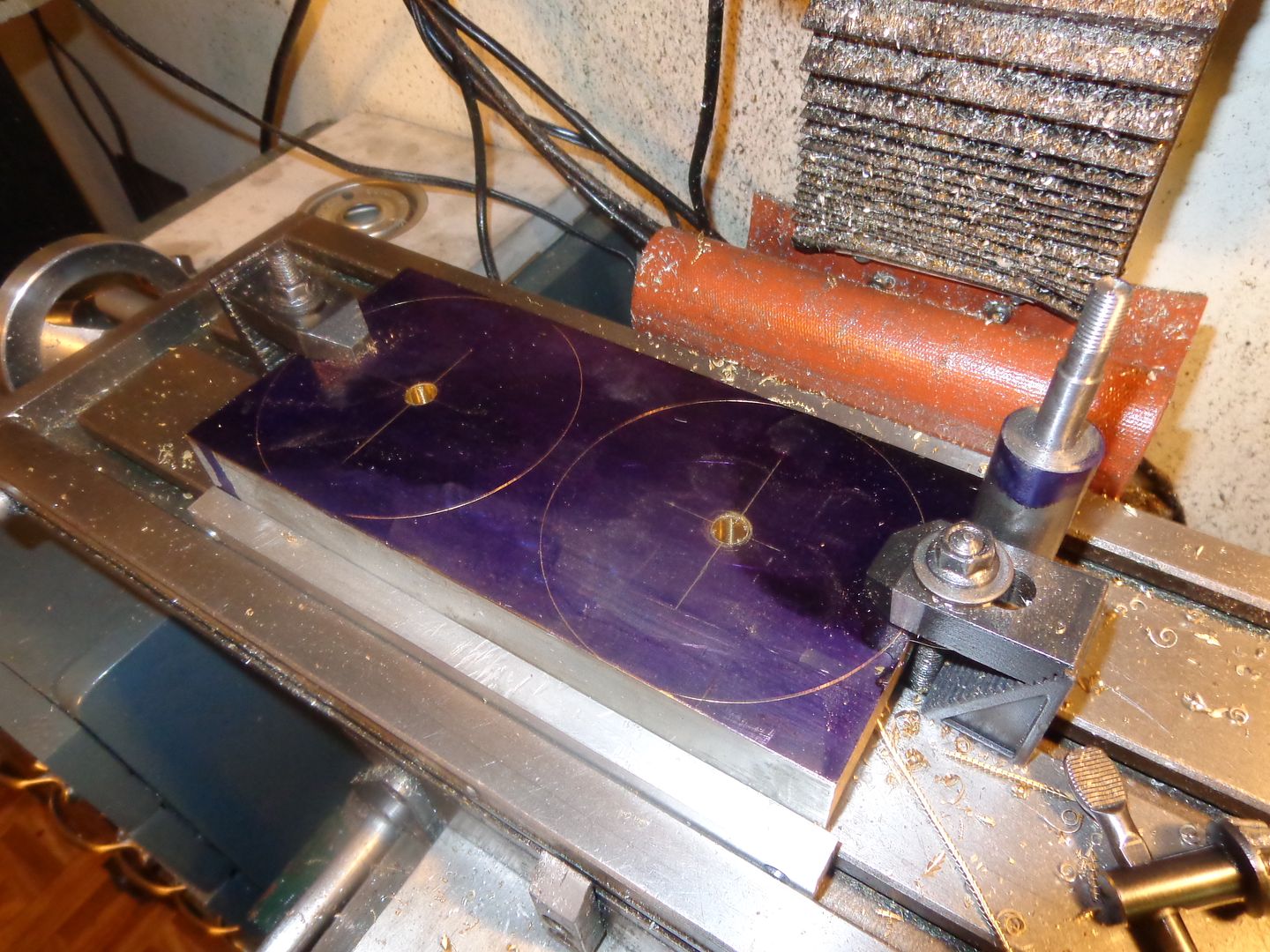
Allright!!! ---I have put out my customers various engineering panic related fires, and now its time to do some serious flywheeling. Damn, I hate it when REAL WORK interferes with my "play work"---but then again, that's how I can afford brass for my flywheels. I am trying to come up with a good plan of attack for these flywheels. Since I am making them from brass bar, I think I will lay out the two flywheels on the bar, then clamp the bar to the table of my mill with a piece of sacrificial aluminum under it. I will then drill and ream the two undersized center holes. This will ensure that the holes are at perfect right angles to the face of the bar in both planes. Then I will remove the bar, saw it in half, turn a slightly undersized center alignment shaft to put through the undersized holes, and clamp the double thickness of bar to my mill table again with a bit of sacrificial aluminum under them, and drill and ream the two .75" offset holes for the crankpin at the same time. Then I will remove them from the table and separate them, saw out the rough 4" diameters on my bandsaw and press in an extra long 3/8" shaft on each one, allowing about 2" of shaft to stick out on the "blank" side of the flywheel. This will give me something to hold onto with the chuck while I turn the o.d. to an exact 4" diameter and do the machining required on the face of each blank. When the metal supplier went to cut a piece of 4" x 3/4" brass flatbar for me, he found that all he had was 4" x 1" flatbar, so he gave it to me for the same price. This means I get to do a clean-up cut on the flat side which has no features. Then I will cut off the "extra long" bit of shaft in the lathe.
 
Last edited:
So, what did we learn today?--Today we learned that a reamed hole in aluminum with a .3735 reamer and a .374 cold rolled shaft is not really a press fit. Oh, its not a "push it through with your fingers" fit, but it sure isn't enough interference to hold a flywheel in place on the shaft. Oh, POOP!!! Next thing I will do is try it in brass and see what happens. We live---We learn!!!!
 
Brian you can always add a very light Knurl to the shaft to make it grow a bit. Straight knurl is preferable but diamond will do if you only have that pattern wheels
 
I may just buy a foot of drill rod, which apparently comes in on size or slightly over. I have lots of options. Will figure it out tomorrow after I ream the brass flywheels.
 
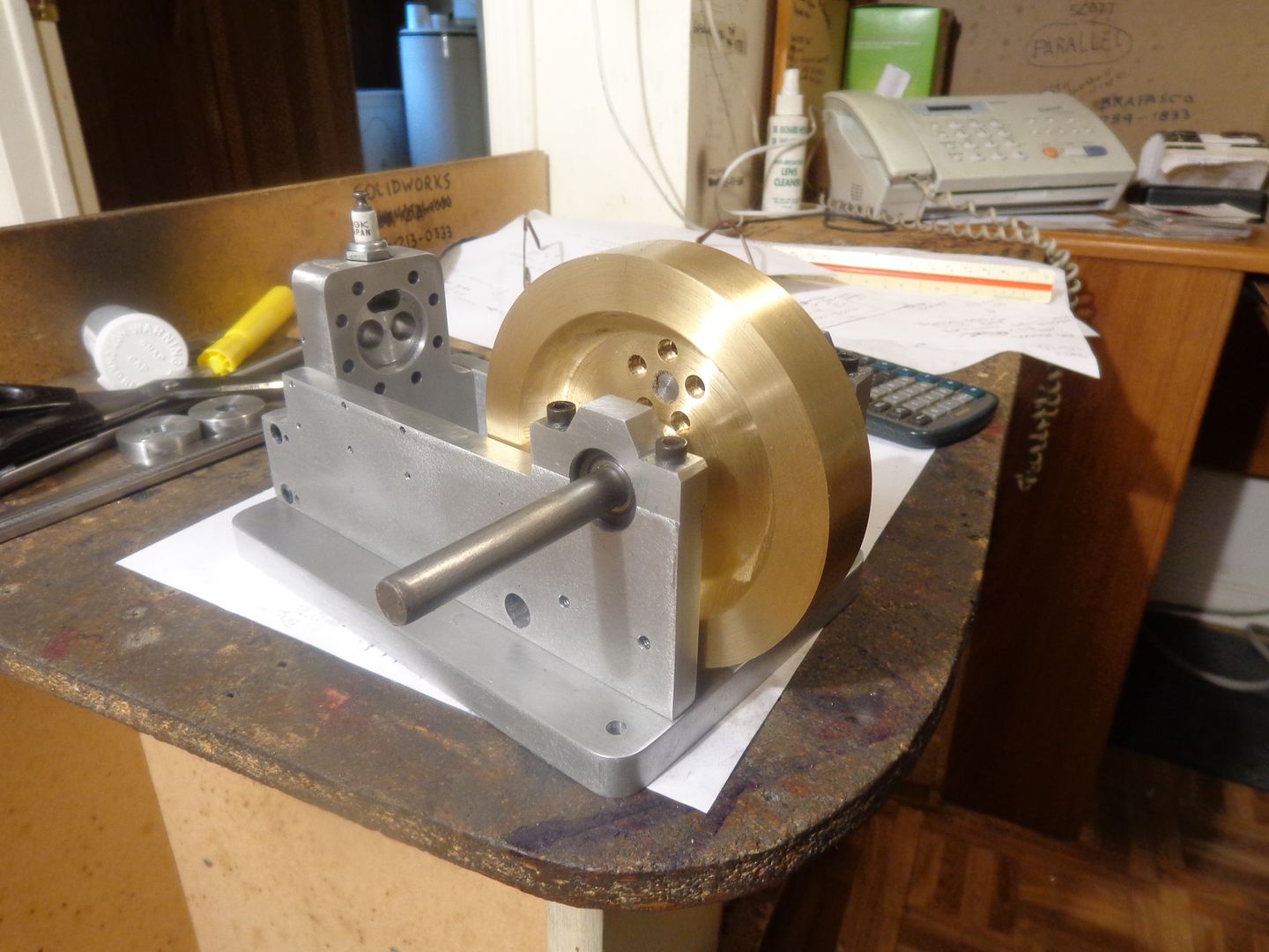
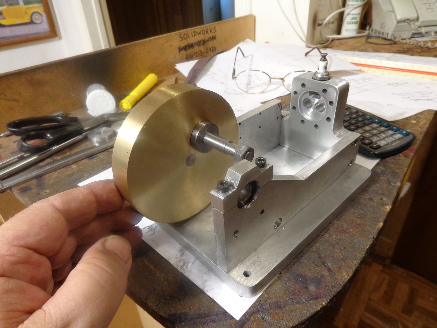
As promised, in process shots. This is two flywheels in the very first stage of "becoming"---laid out and center holes reamed to .3735. And the crankshaft pin, standing at one end, made from 7/8" cold rolled with one end yet to be machined. Fitted this much in today along with half a days engineering work and a trip to the Dairy Queen with 3 grandkids to celebrate the last day of public school for this year.--Yum Yum--
 
I picked up a foot of 3/8" drill rod this afternoon, which mikes at .3755. I am very tempted to try the hot/cold shrink fit method. I wasn't going to do that because the heat would ruin the finish on the brass flywheels but if I press the shafts into the rough sawn brass flywheel blanks it will all clean up during the machining process. I may cut my shafts to 2" longer than finished size and leave them in the freezer overnight. If I can stick the two rough turned brass blanks in Momma's cooking oven, or maybe even the barbeque for an hour that should do it. I will press the shafts completely through each flywheel so I have something to mount in the lathe chuck from each side to turn the flywheels. Then I can trim the end off that I don't want. I might have to polish .005 off the end of the shaft that goes thru the ball bearing.
 
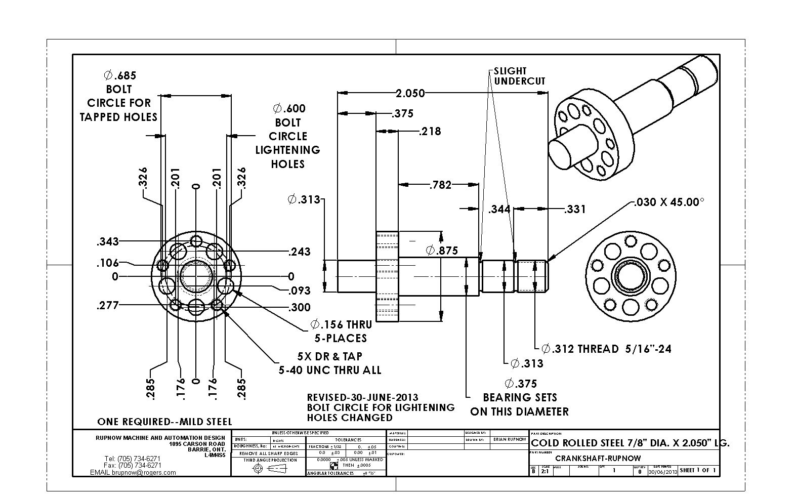
The crankshaft or "crank pin" and the spacers are finished except for the threads and lightening holes. It is shown here, assembled with the con-rod bearing setting in the center. I'm really not certain whether the lightening holes are needed, or even if they will have any effect at all, but since I have to set up the rotary table anyways to put the threaded holes in the crankpin, its not a big deal to pop in a few extra holes. I'm still chewing on exactly what process I am going to employ for retaining the crankshaft end portions in the flywheels. The heat shrink process has a certain appeal, but knowing what a klutz I am, and the thought of carrying smoking hot brass flywheels from the kitchen oven, across the laminate kitchen floor and down the carpeted staircase and out into my garage where the arbor press lives is pretty damned intimidating.----Mrs. Rupnow can be pretty damned intimidating for that matter, and its her kitchen!!!
 
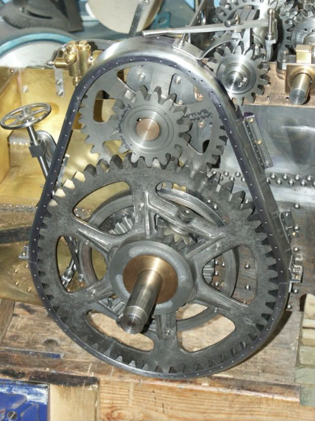
In his marvelous book, "The shop Wisdom of Philip Duclos", he shows this method of retaining a flywheel to the crankshaft. Unfortunately none of the text shown refers to the picture, but what he says is "After pressing, and just to play safe, drill a 3/32" diameter hole --whose diameter is half in the shaft and half in the flywheel. Press in a roll pin and then cut it flush to the surface."---I don't know if a drill will cut half in brass and half in steel, or if it would try to wander off to the brass side because of less resistance than in the steel shaft.--The crankshaft in the picture is 3/8" diameter, same as mine, but his flywheel is steel, not brass.--What do you think, guys?
 
Brian,
I would increase the hole size to .125 then drill using the standard 60* centerdrill probably #1. Also I would off set the hole so that the brass would have say 60% of the roll pin. Finally I would try it out first on some scrap material. :D:D

Pat H.
 
I have used the method several times to stop ROTATION of a pressed on part, its not really one to stop latteral movement. The ones I have done mave used solid pins locktited into tight holes.

A drill will wander into the brass but you could plunge cut with an end cutting milling cutter but would not ant to try it at 3/4"

You can see a couple of pins in this shot on the upper gear at 1 & 7 o'clock

PICT0083.jpg
 
For the shrink fit there's no need to carry the parts out of the kitchen. They should slide together, so just assemble directly from oven/freezer. Arbor press not needed.
 
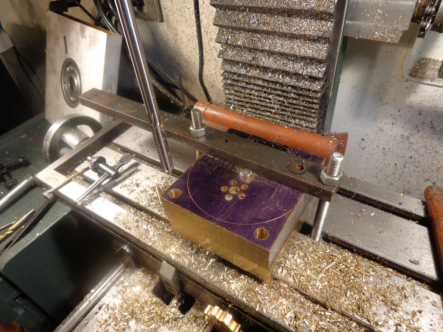
Here are the flywheels in the second stage of "becoming". I have sawed the main block of brass in half and put a close fitting alignment dowel through the center holes. Again, I have lain them flat on the milling machine table with a pair of parallels underneath them to protect the mill table from "drill thru". I have cobbled together a hold down strap from some steel flat bar and threaded rod to secure everything in place. I pick up on the end of the alignment dowel to find true center, then offset 0.75" and drill and ream .312 thru both plates. Then while I am still set up, I drill and counterbore for the five #5 socket head capscrews. (But only to a total depth of 7/8". The bar I have is 1", not 3/4" so 1/4" will be machined of the far face of the top block. I didn't want the 5 bolt pattern to appear in the lower flywheel.) The remaining holes in the outer corners which will be sawn off have been drilled and reamed with my new undersized 0.3735 reamer so that I can do some press fit testing on scrap before I get to the real thing.
 
Experimentation has shown me that 0.374" cold rolled shaft is a press fit into a .3735 reamed hole, but not really a killer press fit. I was able to press the shafts in using my small manual arbor press. However, with the addition of a bit of green Loctite #648 it fits well enough and tight enough that I was able to chuck the rod in the 3 jaw chuck on my lathe and do the turning required on both flywheels.--With both flywheels, they heated up enough under heavy machining that the Loctite let go and they "spun" on the shaft. Only a very little bit, mind you, but they did spin. As soon as they cooled down they had a good grip again. Part of this was due to the Loctite letting go and part perhaps to the expansion of the brass, although it didn't get THAT hot. You are correct about the drill rod not fitting through the ball bearings. This can very easily be "fixed" by spinning the drill rod at about 600 RPM in my lathe and holding some 220 grit emery paper against it. My plan at the moment is to use the drill rod as my crankshaft ends. I will polish the part which must fit through the bearings and leave the part unpolished which fits into the brass flywheels. This will give me an additional 1 1/2 thou interference over what I currently have. I have to go into one of the manufacturing companies that I provide engineering services for on Tuesday, and they have a small hydraulic press, so I will take my new flywheels and drill rod crankshaft bits over with me and press the shafts into the wheels over there. I may have to take a skim cut off the flat (mating) face of both flywheels after I do this. I really don't want a "wobbly" crankshaft when I get finished.----Brian
 
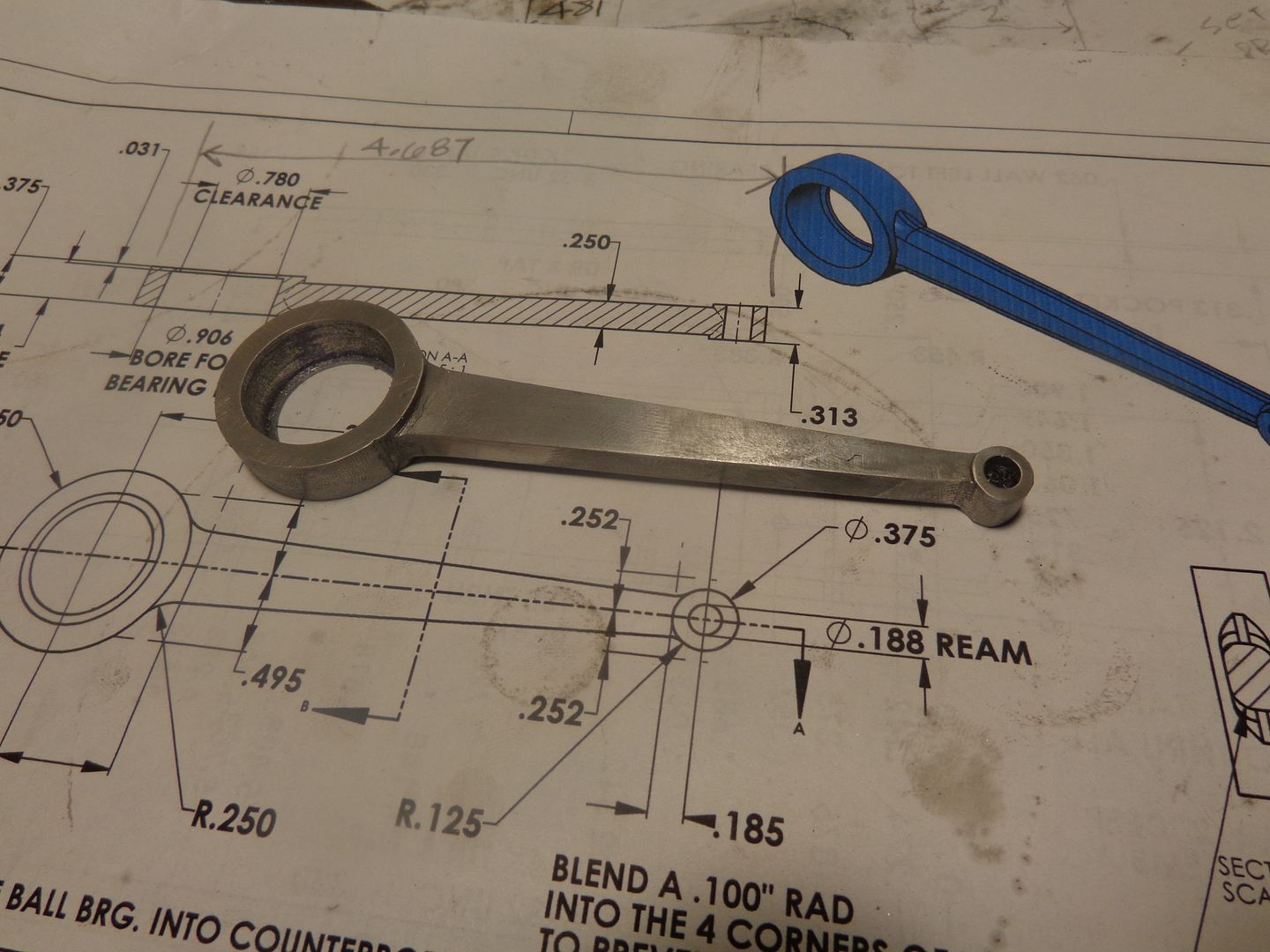
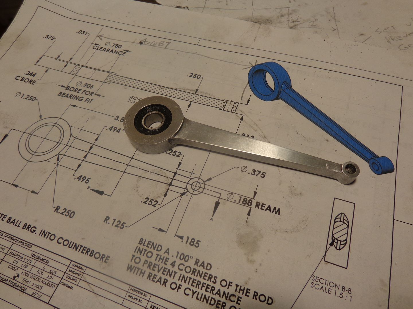
In keeping with my "one part per day " philosophy, I managed to whittle out a connecting rod today. I think it looks a little goofy with that enormous "big end" on it, but Hey, if you go all ball bearing, that's the way it has to be. I have drilled and tapped all of the holes in the crankpin, and put in all of the lightening holes as per drawings posted. My initial plan was to Loctite the bearing into the big end of the connecting rod, but I'm going to put that idea on hold for the moment. I want to get the cylinder and water jacket made and installed, and see if there are any alignment issues before I do any Loctiting. It is very critical that the crankpin be perfectly square to the central axis of the cylinder, to avoid any tight spots or binding in the crankshaft. Once I have test assembled everything, and see that it runs freely, then I will finish drilling the dowel pin holes in the frame and put dowel pins in, and do any Loctiting I deem necessary.

 
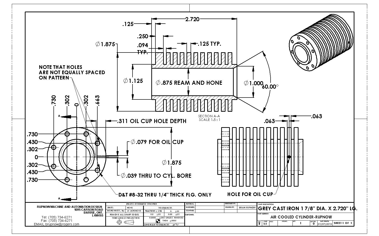
Now---Before you all jump in to remind me that I haven't made any provision for a cylinder oiler----I know that. I have a plan-----And for anybody building this engine as an air cooled version, I will post the drawing of the air cooled cylinder when you are ready for it.
 
Brian,

are my eyes cross or if there's a mistake in the drawing
you have two different bolt pattern for the head if it's air cool or water cool?

Cheers
 

Latest posts

Back
Top