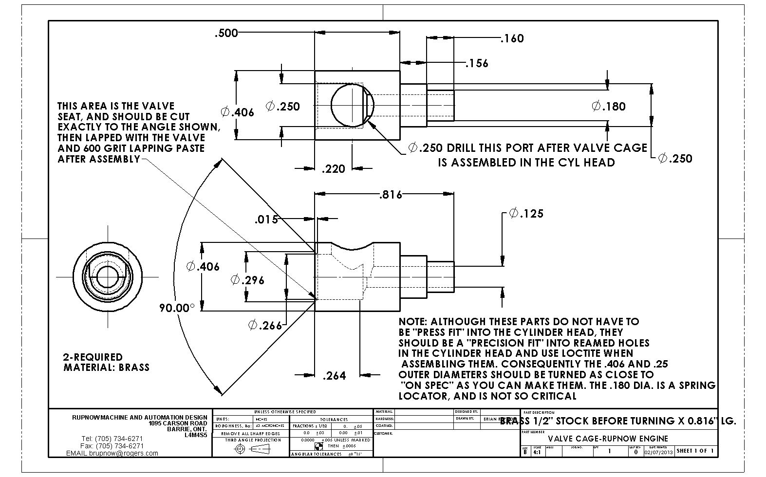
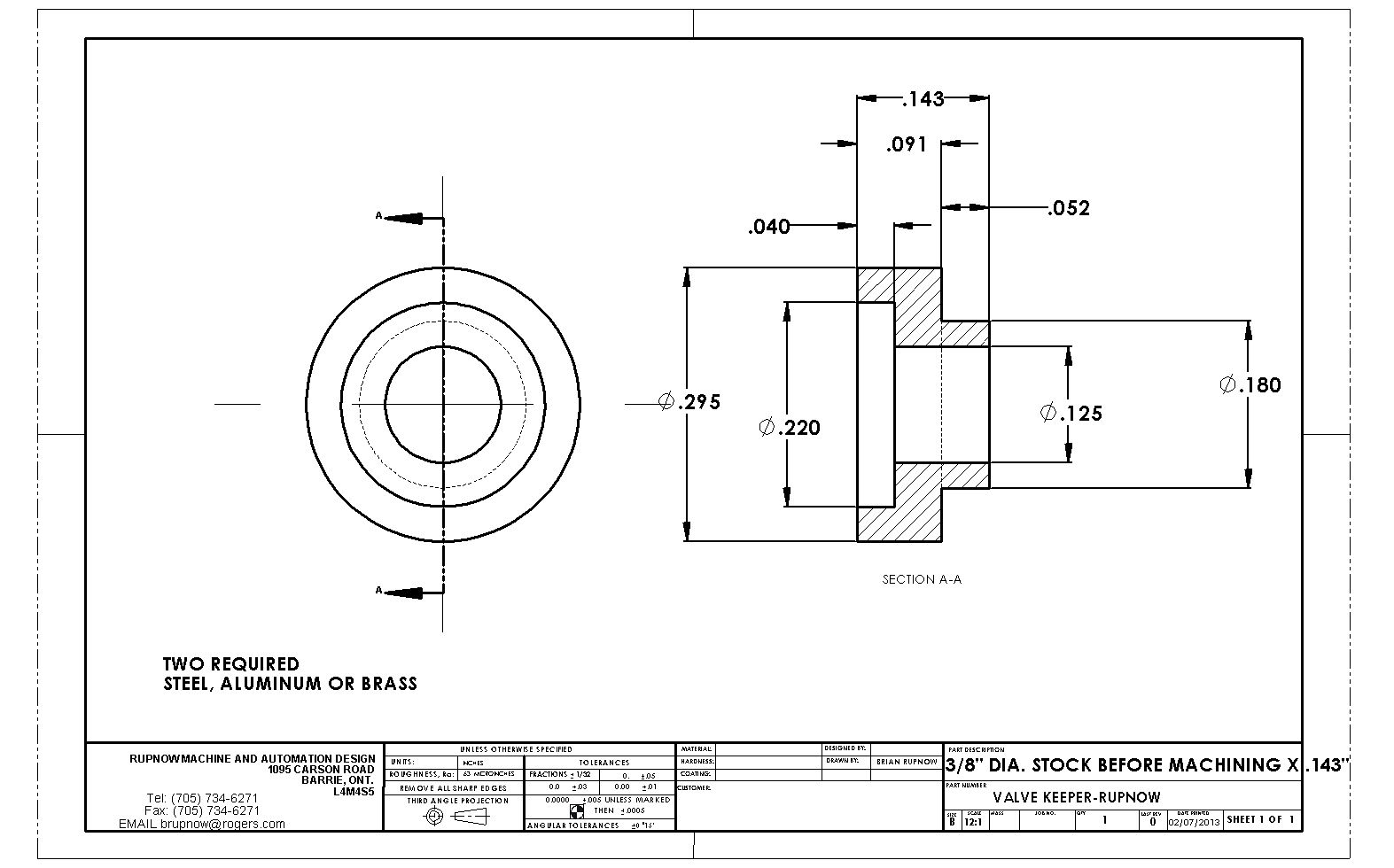
Luc--The air cooled cylinder is rotated 90 degrees to the right in the drawing, so that the "top" is actually on the right hand side. The bolt pattern is the same as the water cooled version.
You are using an out of date browser. It may not display this or other websites correctly.
You should upgrade or use an alternative browser.
You should upgrade or use an alternative browser.
Rupnow i.c. Engine with governor
- Thread starter Brian Rupnow
- Start date

Help Support Home Model Engine Machinist Forum:
This site may earn a commission from merchant affiliate
links, including eBay, Amazon, and others.
canadianhorsepower
Well-Known Member
- Joined
- Oct 22, 2011
- Messages
- 1,671
- Reaction score
- 324
Brian ,
this is what happen when you read drawing without glasses Rof}Rof}
I'll be posting pictures later today, bottom plate ,side plate cyl head
bearing cap
I couldn't get the material on time for the flywheel
cheers
this is what happen when you read drawing without glasses Rof}Rof}
I'll be posting pictures later today, bottom plate ,side plate cyl head
bearing cap
I couldn't get the material on time for the flywheel
cheers
Great stuff Luc!!! I had the water cooled cylinder drawings posted briefly but I have taken them down because of some "fitment" issued that were showing up. I will repost them after I have built them and resolved any issues. You are safe to go ahead and make the air cooled cylinder.
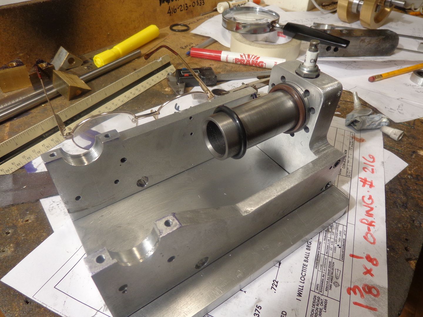
I was working this morning, machining the cylinder for the water cooled version of this engine, when I had a sudden terrible thought.---What if I can't get an o-ring the size I need? Wife had some serious gardening planned (Great way to celebrate Canada day), so I shut down the lathe and went to play in the garden. Of course by the time we got finished, I needed a shower, and then I needed a nap--getting old sucks!!! Finally made it down to the computer and looked up 1 1/8" i.d. x 1/8" cross section O-rings, and it is a standard size, #216.-Ah, I knew it was all along. Should never doubt myself!! Anyways, I'm too pooped to do any more machining today. This idea of having a water jacket which seals to the cylinder with an o-ring at each end instead of a press fit has been on my mind for a long time. I used a press fit seal on both the Kerzel and the Odds and Ends hit and miss engines and they worked, and have never leaked. I will build this engine with o-ring seals, and see how well it works. I have every reason to think it will work fine, and if it does, I avoid the craziness of interference fits between the cylinder and water jacket. If it doesn't work as well as I thought, then I will remake either the cylinder or the water jacket and make it a press fit. I will have the cylinder, water jacket and seal ring finished by next weekend, so let me make it and test it before I lead someone down the garden path.
canadianhorsepower
Well-Known Member
- Joined
- Oct 22, 2011
- Messages
- 1,671
- Reaction score
- 324
Brian,
I'm going air cool, give me your opinion
for one I hate cast:hDe:
I was going to go alu for the piston
SS for the cylinder
and put a press fit aluminium over the sleeve
and the run the fin on it:hDe:
I'm going air cool, give me your opinion
for one I hate cast:hDe:
I was going to go alu for the piston
SS for the cylinder
and put a press fit aluminium over the sleeve
and the run the fin on it:hDe:
Luc--Firstly, I think the air cooled cylinder will be a lot less work. Since this engine is intended to be a "hit and miss", it will draw in enough room temperature air during the "miss" cycles, that it probably doesn't need to be water cooled.-That is what other experienced engine builders have told me, and I believe them. I like the water reservoir style, but that's just a personal thing. Aluminum for the piston should be fine. I have an aluminum piston running in a 316 stainless cylinder on my Kerzel hit and miss engine, and it performs fine using a Viton o-ring. I think many of the long time engine builders really like cast iron for the cylinder and piston because of its high carbon content, which makes it somewhat "self lubricating---which is especially important if you are going to use cast iron rings. With a Viton ring you can use almost any material for piston and cylinder as long as it has a nice smooth finish on the inside of the cylinder. The question of a stainless cylinder with aluminum sleeve fins pressed on---I don't like that so much. Even with a heat conductive copper paste at the joint between the two surfaces, you don't get very good heat transfer. I have a lot of experience with heat transfer between two surfaces, and it just doesn't work efficiently. You can try it and see. If you don't plan on running your engine for long periods of time or under any "load" condition, you MIGHT get away with it. That's the best advice I can give.---Brian
Gents , With reference to using Stainless steel for the Liner. I would not use it. On my Sterling Engine I used a stainless steel liner for the power cylinder ( Finned for Air Cooling ) in conjunction with Aluminium Fins as per what Luc is trying to use. The power piston is cast iron.
The bore was 22 mm and the piston to bore clearance about .001 inch.
The Liner was Heat Shrink Fit in Cylinder to get maximum heat transfer and the external surface of the sleeve was fine polished as well as the bore of the cylinder.
Any dirt or carbon that gets in there will pick up on the stainless and cause problems.
The Cylinder does run hot after a period of time.
In hindsight I should've used cast iron for the cylinder liner and possibly have turned the complete cylinder out of cast iron as it does tend to be self lubricating.
( I get my Cast Iron from a local foundry and they normally give me the sum off cuts for a 12 pack of beer )
Next time I get the Sterling Engine pulled apart I will get the piston Teflon Coated so I can run the sterling engine non lubricated.
Regards Ralph
Just some further though with regards to cooling.
In most 4 stroke OHV engines only about 20% of the heat created in the combustion process is dissipated by the cylinder cooling system.
The cylinder is also partially cooled by the intake cycle and cold gas entering the cylinder and when the piston is at TDC some heat is lost to the crankcase atmosphere.
The Cylinder Head however ( overhead valve ) has to do most of the cooling as it also has the exhaust port generating a huge amount of the heat that it has to deal with.
Maybe some fins milled on the cylinder head would help reduce the heat build up.
Had a bit of experience in Cogeneration and reclaiming waste heat from big Gas Engines. ie Lube Oil / Engine Jacket Water / Exhaust Gas
Ralph
Last edited:
Last edited:
And one last bit before I have to go out to see a customer---
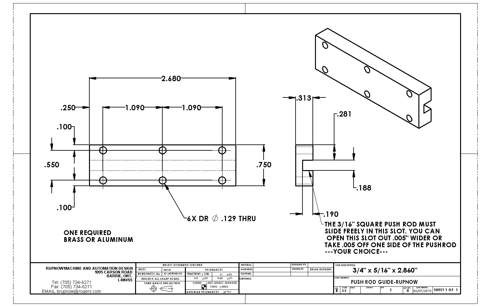
View attachment PUSH ROD GUIDE-RUPNOW.PDF

View attachment PUSH ROD GUIDE-RUPNOW.PDF
canadianhorsepower
Well-Known Member
- Joined
- Oct 22, 2011
- Messages
- 1,671
- Reaction score
- 324
Hi Brian ,
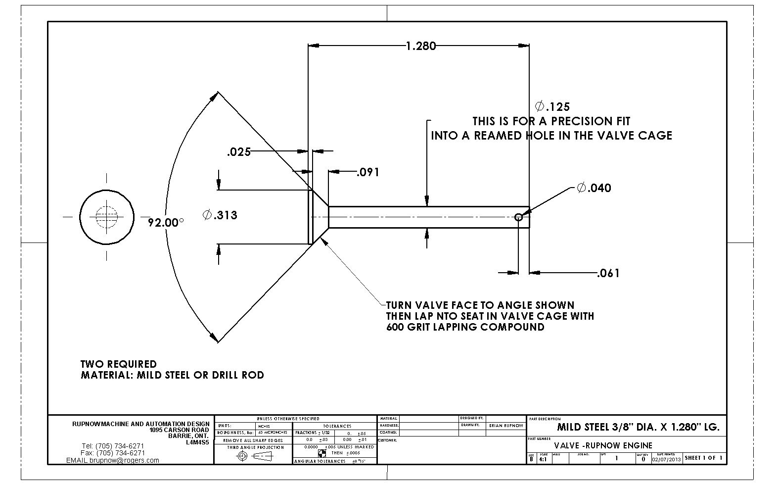
their are 2 length missing on the valve (see picture)
I decide to go with a meddle bearing on the big rod end, more contact surface

their are 2 length missing on the valve (see picture)
I decide to go with a meddle bearing on the big rod end, more contact surface

You don't need a dimension for either as you have the OD and stem dia plus the angle.
J
J
Last edited:
canadianhorsepower
Well-Known Member
- Joined
- Oct 22, 2011
- Messages
- 1,671
- Reaction score
- 324
You don't need a dimension for either as you have the OD and stem dia plus the angle.
J
what your saying is to cut at 92 degree till I reach .125 in diameter
Or just a bit of simple triganometry.
Easiest way is to support the 1/8" end with your tailstock ctr and machine down the 5/16" stock to the required 1/8" dia say 1/4" over length. Then cut your angle before parting off leaving the 0.025" .
You can then hold the valve in a collet or split bush and machine to the correct O/A length removing the centre drioll hole in the process and you don't even need to know what the two lengths in question were.
J
And this afternoons workshop adventure brings us--TA-DA--A cast iron cylinder!!! Its not honed nor lapped yet, but that will happen tomorrow morning. I had to work over at a customers factory this morning, and it was close enough to the Hercules o-ring warehouse that I picked up two #216 size O-rings. The black one is just common elastomer, but the brown one which sets closest to the head is Viton. I probably don't need the high heat capacity Viton o-ring, but they are all the same price so I figured I might as well get one. The cylinder is a "close" fit into the counterbore in the head.--that's what's holding it there for the picture. The bolts actually thread into the water reservoir and "squeeze" the cylinder against the head---and yes, there will be a head gasket between the far side of that flange on the cylinder and the cylinder head.

jwcnc1911
-jwcnc191
- Joined
- Mar 19, 2013
- Messages
- 603
- Reaction score
- 86
Man, your making good time on this engine Brian! Nothing like being responsible for other people's time and money to motivate you, huh? Looking good. I can't wait to see it run. It's been enjoyable up to this point for sure seeing this "independent team build" going down.
Thanks JWCNC---It always gives me encouragement to see that other people are following my thread.---Brian
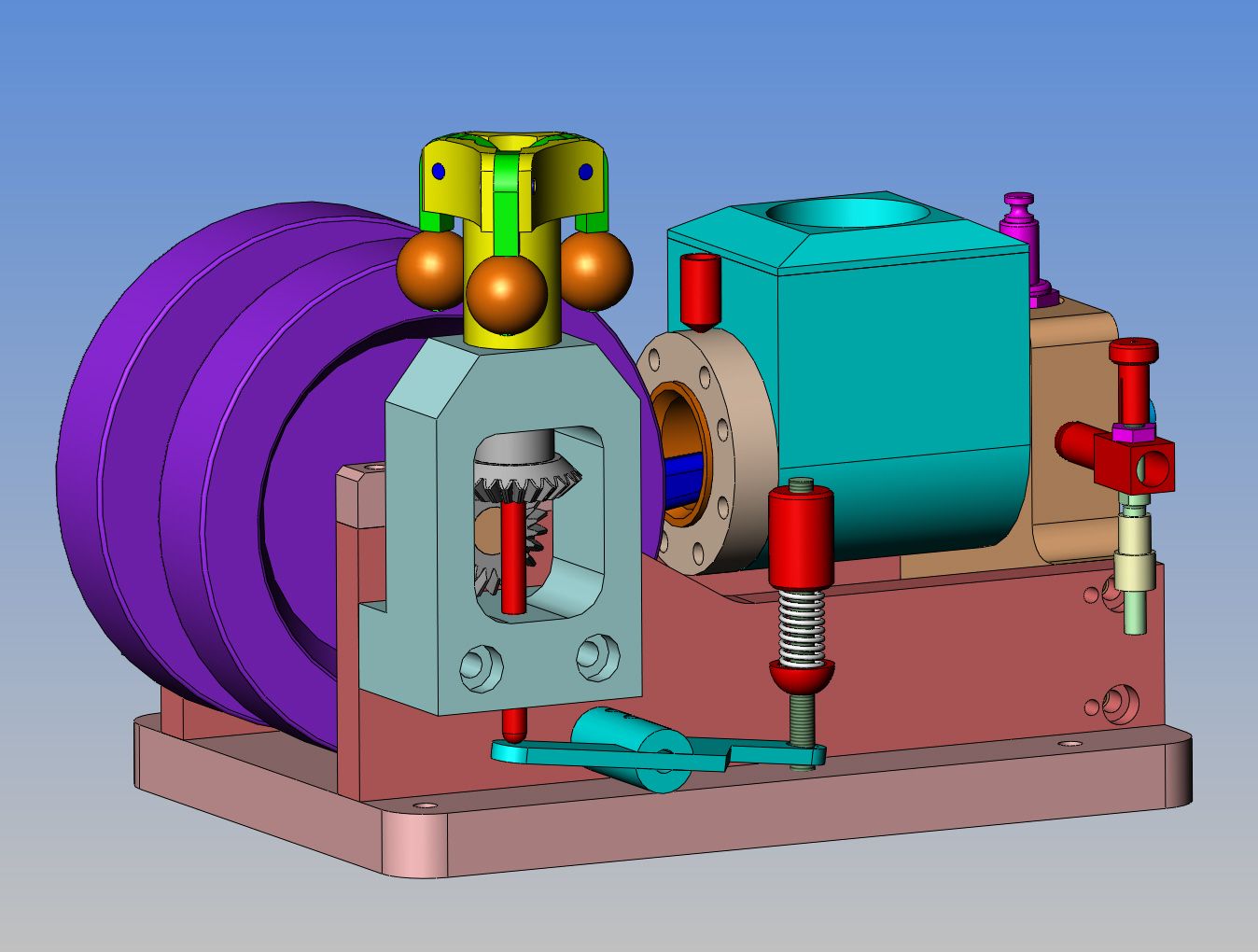
I had to do some head scratching to come up with a place to put the cylinder oil cup. I admit--I just plain forgot the darn thing with my initial design. Remember I said I had a plan---Well, there is no reason for the water cooling reservoir to be so long. The last inch of the cylinder farthest from the cylinder head serves no real purpose other than to give a place for the piston to slide in. There is no combustion happening back at that end. However, I like the look of the large water reservoir. To solve my problem of where to put the oil cup, I shortened the water reservoir by 1/16", thickened up the "water jacket retaining ring" by 1/16" to 3/8" thick, and put the oil cup which is 5/16" outside diameter through the center of the retaining ring and the top of the cylinder. Of course, this means I can't really drill the hole for it until the entire engine is assembled, but that's okay. It just gets loctited into place anyways.

Similar threads
- Replies
- 28
- Views
- 4K
- Replies
- 27
- Views
- 3K
- Replies
- 61
- Views
- 8K


