Rupnow i.c. Engine with governor

Home Model Engine Machinist Forum

Help Support Home Model Engine Machinist Forum:

This site may earn a commission from merchant affiliate links, including eBay, Amazon, and others.
Look good, Thm:eek:ne more question is the rod going to be a 2 pcs or single
and what is the rod bearing number??
 
The rod is a one piece unit and it gets the same bearing as the crankshaft. That is why I am going with the bolt together crankshaft---So I can run a ball bearing on the rod journal. There will probably be a bronze bushing in the small end of the con rod. I just haven't shown it yet.
 
Last edited:
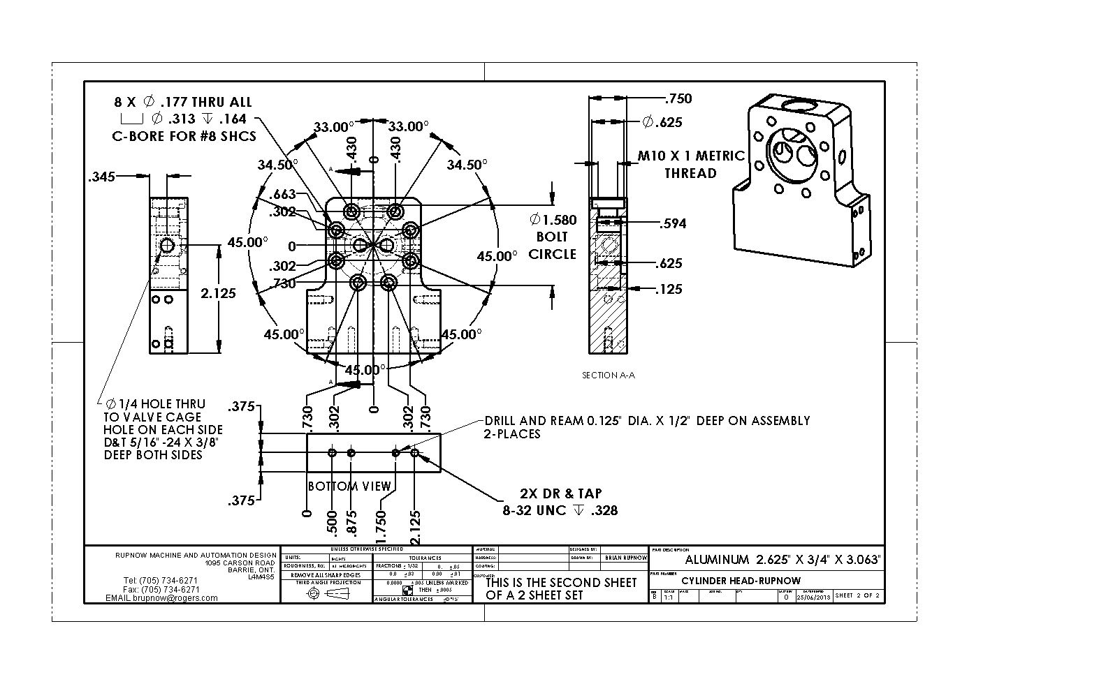
Things will slow down a bit now. I had a call from a customer in trouble yesterday and have to do a panic redesign on some automation equipment. This won't be a lot of work but will tie me up for 2 or 3 days. I ordered an undersized reamer this afternoon to ream a "press fit" hole in the flywheels, as that is where I will be moving to next in this build. The flywheels and crankshaft and con rod are all kind of inbred on this engine, so I will probably be working on all of them at once. I discovered no errors in any of the detail drawings I have posted, but I did notice that the top two bolt holes in the circular array on the cylinder heads is missing, so I will repost that drawing right now.---Brian
 
I can't figure out how to go back and change an attached pdf file, so I will just repost it here. There were no errors, just a missing dimension.--No, can't do that--there is something screwy with the forum tonight--can't attach a pdf. A jpeg will have to do.


View attachment CYLINDER HEAD-RUPNOW.PDF
 
Last edited:
Thanks for your (misplaced?) confidence in me Rod Thm:

Rest assured Brian, I'm with you. I'm just waiting for some funds to clear so I can order some materials. I don't have anything in stock to start just yet. I fully intend to have my first part finished this week.
 
cogsy---I'm looking foreword to seeing your first post. That will make 2 Canadians, one Englishman and one Aussie building this engine.--This makes all the other nationalities out there either A----Wimps for holding back and not joining us., or B---People wiser than us who are going to set back in the bush and wait to see if this engine is successful!!!:eek::eek:
 
Yes Luke, you are probably right. I was trying to keep the flange the same diameter as the o.d. of the con rod. I will do a redesign on that part.---Brian
 
cogsy---I'm looking foreword to seeing your first post. That will make 2 Canadians, one Englishman and one Aussie building this engine.--This makes all the other nationalities out there either A----Wimps for holding back and not joining us., or B---People wiser than us who are going to set back in the bush and wait to see if this engine is successful!!!:eek::eek:


Hey ... Don't count me out yet. :p:p I'm just under the weather a bit but will be posting soon. So far I have been only watching as I can't get shop time until I'm fully functional.
What I have done is taken the Base drawing and modeled it using SW2013, will be doing the same for the two side plates ... probably today.
Hope to be posting Monday next week or sooner.;);)

Pat H.
 
Yes Luke, you are probably right. I was trying to keep the flange the same diameter as the o.d. of the con rod. I will do a redesign on that part.---Brian

Brian, why not use a simple keyway on the shaft and pully and
a bolt at the end with a washer
 
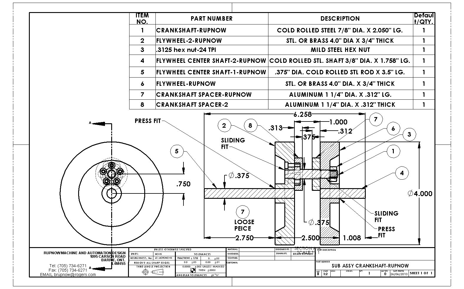
I have reworked the crankshaft drawings and reposted the drawings which were affected. I realize that I could have probably used a crankpin that was turned down and threaded at both ends, and probably have saved some work (maybe a lot of work) in the process. However---I have had problems with that on another engine so this time I am going to the circular array of #5 socket head capscrews. I have lightened the crankpin as much as I dare, and also lightened the aluminum spacers. I know this may seem like a lot of offset rotating mass, but think about the weight in the crank throws on a "typical" crankshaft.---This engine doesn't have any "throws", so the offset weight difference between this crankshaft and one of a more "typical" style is not all that great. If I find that this engine has any issue with "out of balance" (greater than any other hit and miss style engine) then I will drill a few holes in the flywheels themselves to balance things.--That's one thing that you can easily do when you have solid flywheels.
 
Last edited:
Back
Top