Rudys Radial 5

Home Model Engine Machinist Forum

Help Support Home Model Engine Machinist Forum:

This site may earn a commission from merchant affiliate links, including eBay, Amazon, and others.
Zee, It works great when I use small dia collets I can turn the tip to just smaller that the dia of the collet.
 

That's alot of nice parts Dave.

I really like this engine.

 
Looking fantastic
 
Got some new work done in between the honey do list.

I started with setting up the part in the 5c spin Index. I needed to align the cylinder hole at top dead center and flat. I made a piece to fit the bore of the Block and put it in the quill and lowered it into the bore which aligned it to the quill.
DSC01443.jpg

DSC01444.jpg


I then milled the 5 flats to hold the transfer tubes
DSC01446.jpg

DSC01447.jpg


Next step is to drill the tube holes
DSC01448.jpg


Next is to drill the 10 2-52 holes and then tap them
DSC01449.jpg


The last thing to do was to drill and tap the 10-32 hole for the air intake
DSC01450.jpg


Got both valve bodys done next thing to do it the rotary valve's which area i job in them self.

 
March to July...that was some honey-do list. :big:
Glad you're back at it.
 
Back at it again today. Thank god its a little bit cooler in the basement. 98 degree's outside with what feels like 100 percent humidy.

I worked on the intake tube base parts I need 10 of them so I used autocad to get the numbers I needed to make 5 at a time.

DSC01453.jpg


This is after the holes in 5 of the parts were done.
DSC01458.jpg


Now I need to make them to size. Again I used Autocad to plot where I need to be. digital Readout sure helps make things easier.
DSC01460.jpg

DSC01461.jpg


Here Is a picture of the parts cut out still on the fixture
DSC01464.jpg


Here is a picture of some of the parts. So many small bolts 100 plus 2-56 bolts.
DSC01465.jpg


I also made the crank bushings. Here is a picture of the bushings one set is already in the one nose cone the other need to be installed.
DSC01468.jpg


Carl I should have had breakfast the burger was not at all good :big: :big:
 
dreeves said:
Carl I should have had breakfast the burger was not at all good

That's a real bummer. It's a diner after all. I'd noticed you hadn't finished it and was thinking you were just keeping your trim shape. (I'll eat everything in front of me...if I like it.) I hope that doesn't put you off from the diner. :big:

And yeah...it has been really hot around here.

I really enjoyed seeing your engines...and I learned a few things too!

 
Zee, The diner is fine. Just no burger next time. Stay Cool 90's all week
 
Well all is well with the finger so it was back into the shop to make some chips.

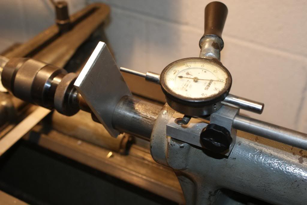
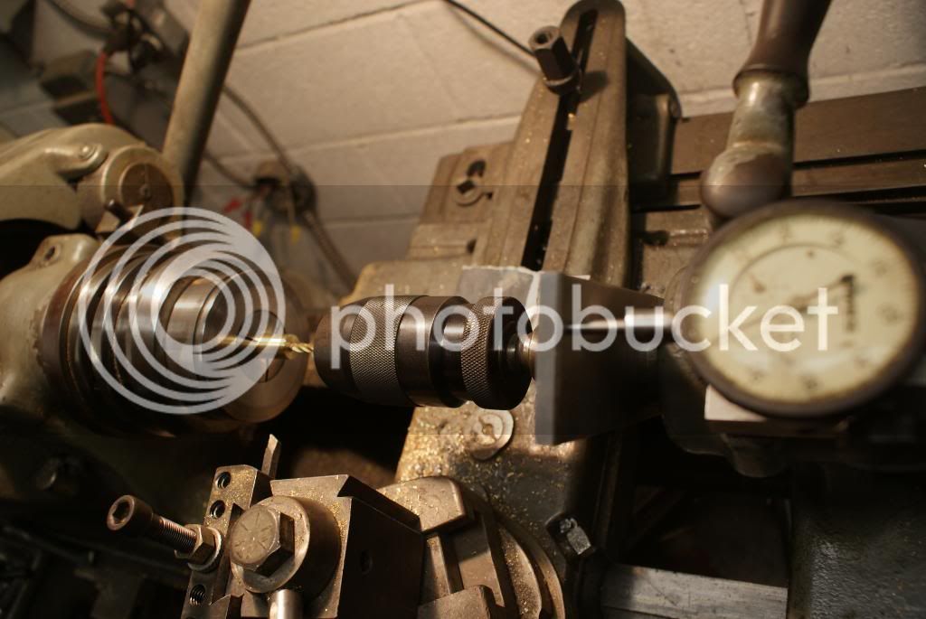
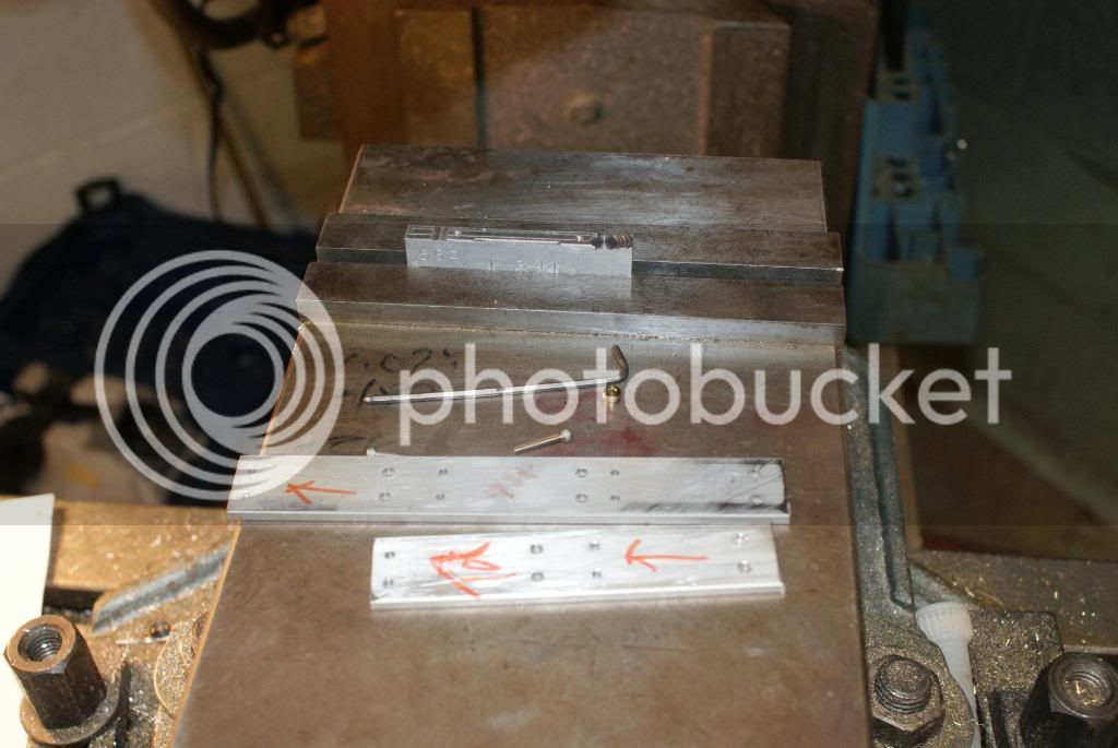
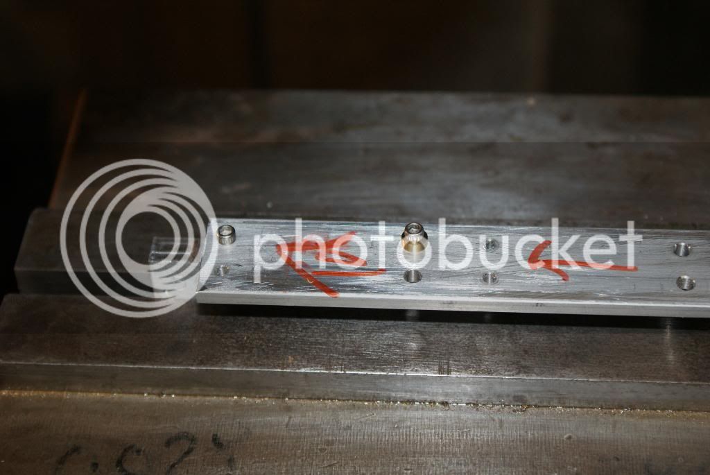
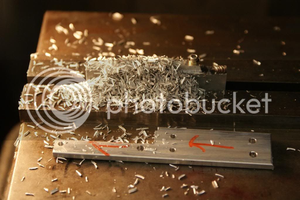
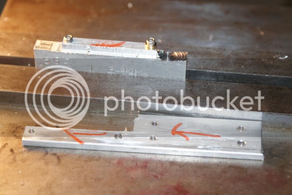
I started with a new shop tool. I needed to mount an indicator to my tail stock to be able to accurately drill to depth. On my tail stock I had a hole where white lead was put for use with dead centers. I was told by a my old shop teacher that it was the best. I drilled the hole to the tap size for the 3/8 bolt. I then made the holder from aluminum. The .500 shaft is locked into place with a barrel lock. It worked great to bore the .1875 holes .430 deep into the rear of the pistons of the Radial 5

DSC01541.jpg


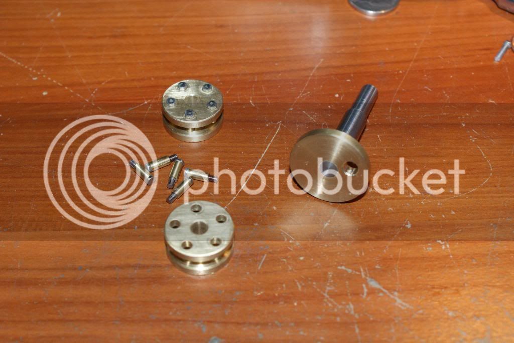
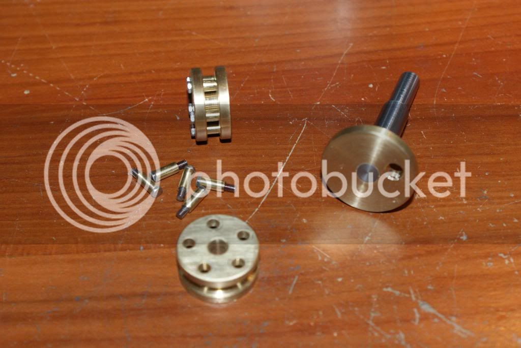
Now for the engine parts.

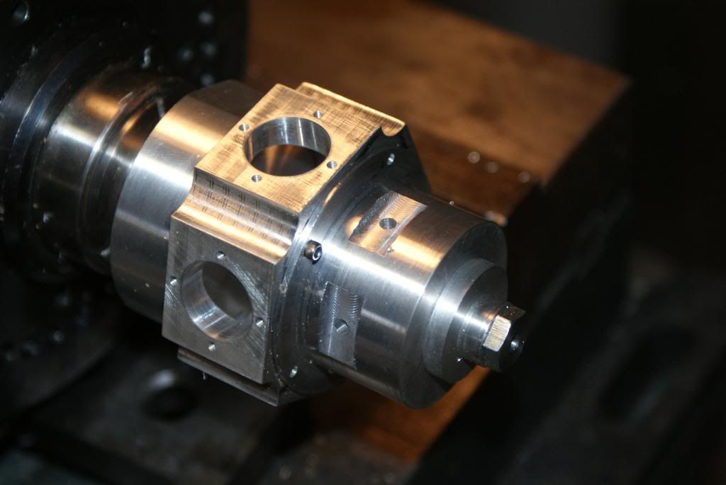
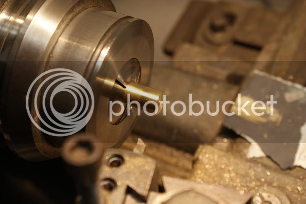
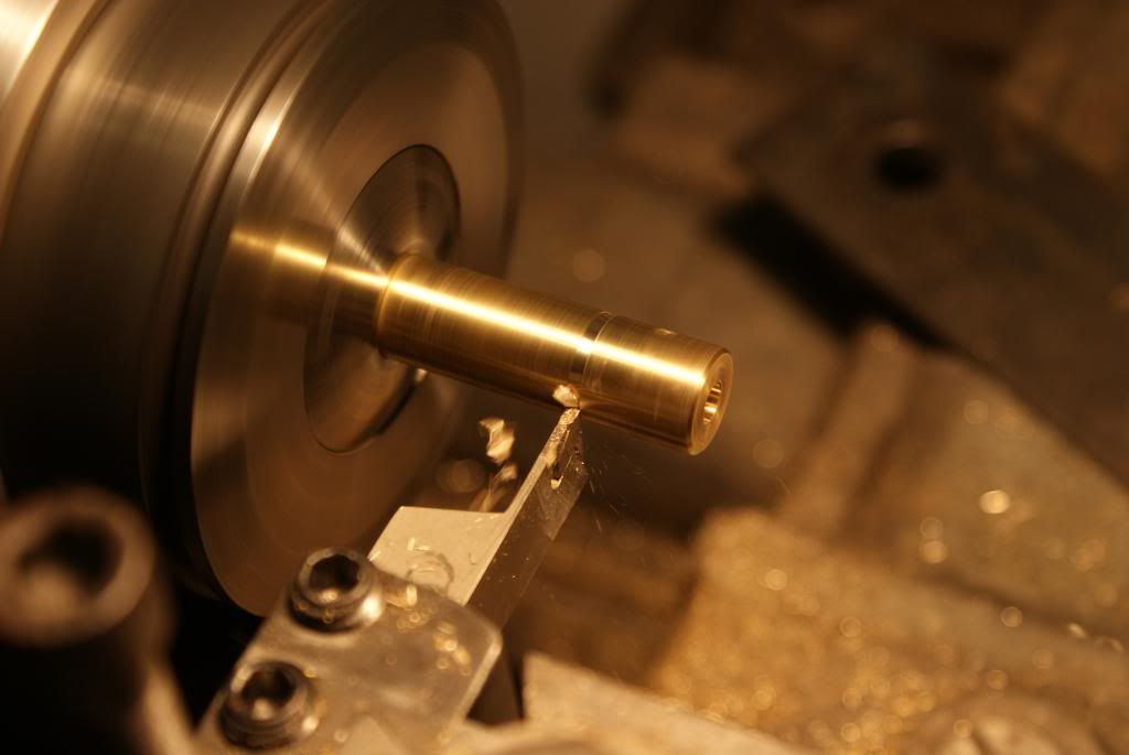
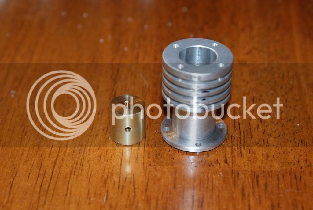
I started with .500 dia brass rod in my collet. First was to face it
DSC01540.jpg


The next step was to bore the .1875 dia hole .430 deep. time to put the new tool to work.
DSC01542.jpg


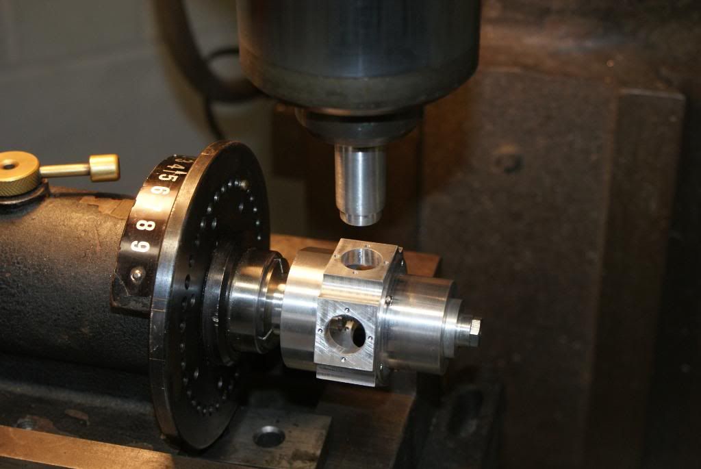
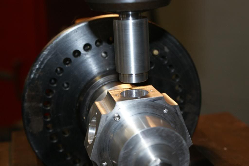
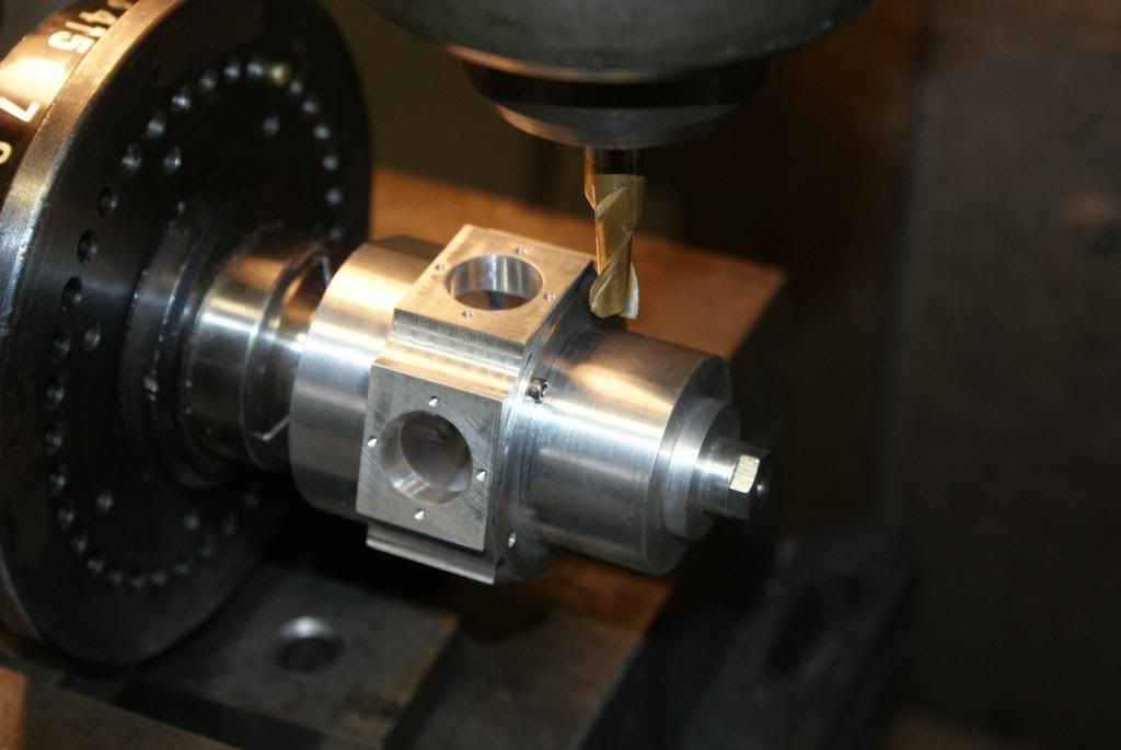
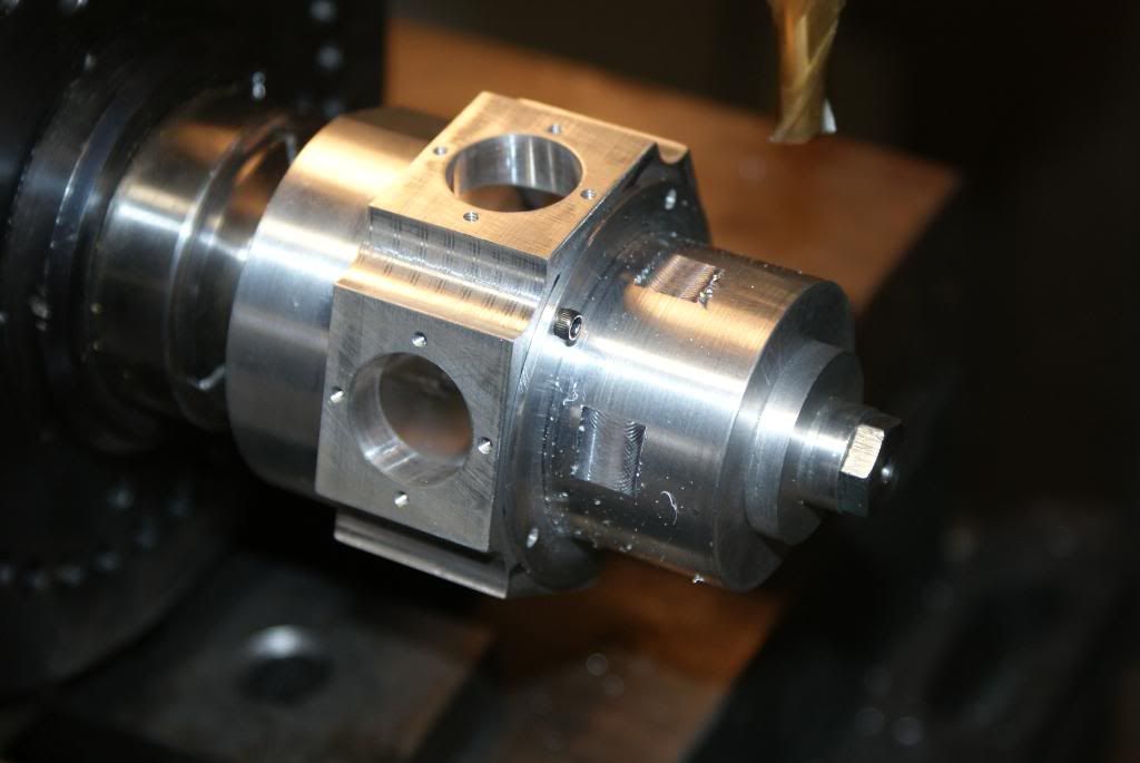
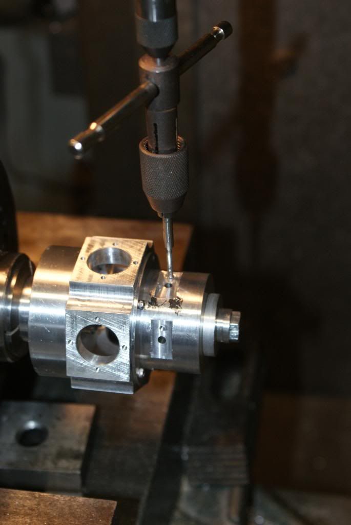
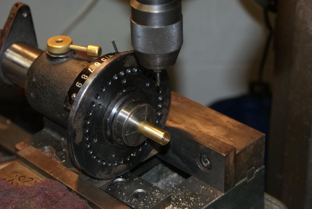
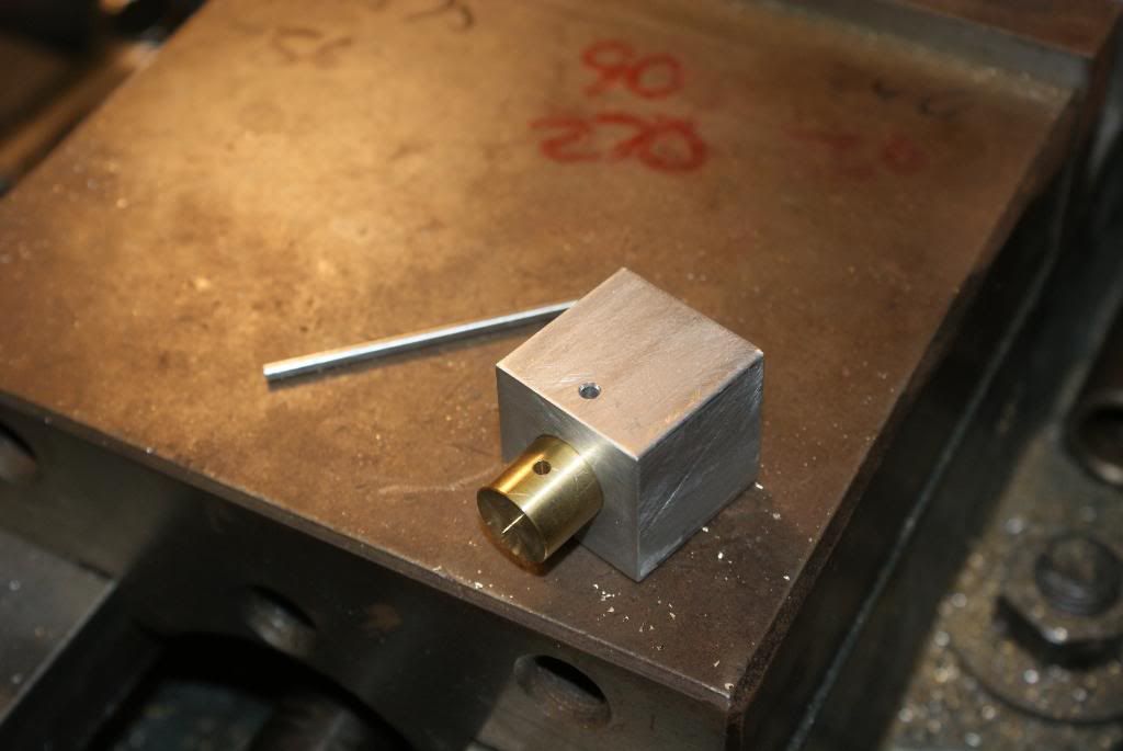
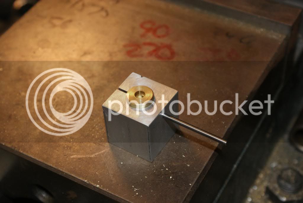
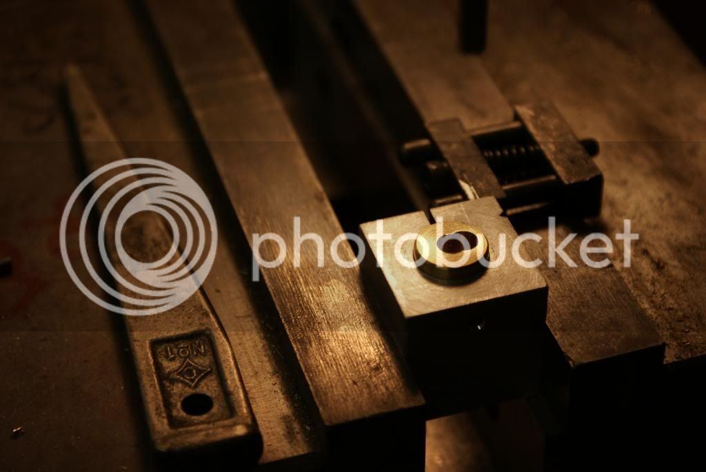
The next thing was to drill the wrist pin .09375. I used my spin indexer to hold the rod. I cheated when moving the center drill into location. Instead of using the edge finer I just moved the piston over to just touch the center drill and then moved 1/2 the dia which was .0625.

DSC01543.jpg


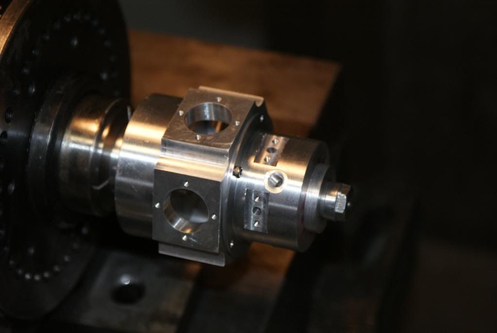
I then moved back to the lathe and cut the piston close to the finished length. I will then face them to the final length. I hope to finish them this weekend by cutting the bottom into the oval shape the .430 deep hole done earlier will speed the process.
DSC01544.jpg


I will need to make another fixture to hold the piston for the final job. I will post more pictures as I make the parts

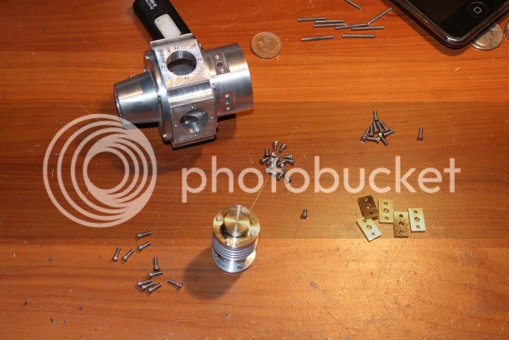
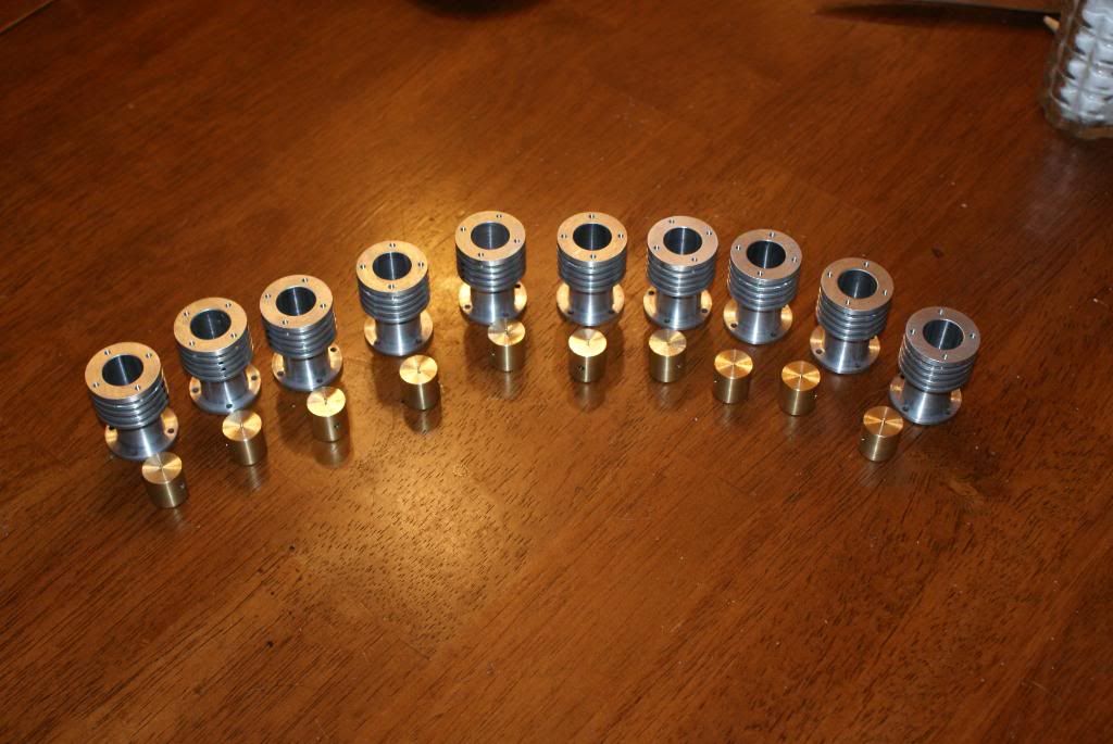
Here is a picture of the 10 pistons and 10 cylinders
DSC01545.jpg

DSC01546.jpg


Thanks Carl. Let me know when your ready for the diner
 
dreeves said:
Let me know when your ready for the diner

Funny that. I was thinking about that today. I was thinking when I got the loco running of calling you for a diner and seeing that Upshur of yours.

No loco...no diner. :big:

 
your loco does that count :big: :big:
 
After following this thread for a bit I remembered a radial aircraft engine that I saw at NAMES about 10 years ago in which the crank was stationary and attached to the aircraft frame, and the cylinders rotated (I think this type of engine was used on very early WW1 biplanes). Has anyone ever seen an air powered model of this type? I think that would be a very interesting engine to build.

Jack
 
Not particularly sophisticated, but I did this one: [ame]http://www.youtube.com/watch?v=Fnp-lbJaOQI[/ame]
 
Got some work done over the long weekend. Here is the fixture to mill the relief in the piston for the rod.
DSC01551.jpg

DSC01552.jpg

I made the fixture with a split along one side to clamp the piston in the vise the pin aligns the piston to mill the relief in the right direction. The pin is removed prior to milling. The center hole was done in the lathe to speed the cutting the slot. The cutter was moved .096 then the cutter is dropped to down to cut the slot the table was then moved to the other top at depth to complete it.

Here is a picture on the first cut
DSC01549.jpg


Sorry I did not take a picture of the second cut.

A$ll to pistons are done so I moved on to the crank disk which holds the master rod and the slave rods.
These were made to print then I rembered that the pins were a pain to make as they are .09375 with a 2-56 thread. I did a quick check with auto cad to see if I could open then up to .125. With the part drawn as a solid in autocad I found that making the pins .125 would not cause and interference issues I went and remade them with .125 holes on top with 2-56 threads on the bottom. The pins were so much easer to make. I just drilled the .125 dia rod with a .086 clearence hole and cut to length.
Here are pictures of the finished crank disk's and pins along with one of the cranks.
DSC01556.jpg

DSC01557.jpg


Rain Made it easy for me convince myself to get some more done on the engine.

I got the blanks made for the rods. In the chuck is the fixture to cut the rods.
DSC01558.jpg


The fixture holds the rods so I can do all the cutting around the outside. The matreial is .750 wide which allowed me to make two rods one on each side. I also made 3 in a row giving me 6 on the one blank and 4 on the other.
DSC01560.jpg


I then cut the shape with a .125 mill cutter.
DSC01561.jpg

DSC01562.jpg


This is what it looks like after I done on the mill. All that is needed is to round the ends.
DSC01564.jpg


Here are the first 5 done with the crank disk
DSC01579.jpg


Here is a picture of the complete set of parts in the cankcase
DSC01580.jpg

DSC01582.jpg


Thanks for looking thats all I got till I get some more time in the shop.

 
Looking good Dave.

Is there a reason why the end of one of those rods is different from the others?
 

Latest posts

Back
Top