'Poppin' Flame Licker Engine

Home Model Engine Machinist Forum

Help Support Home Model Engine Machinist Forum:

This site may earn a commission from merchant affiliate links, including eBay, Amazon, and others.
Nick,
Congratulations, it came out great! I am interested in hearing how the graphite performs over time.
I don't know if you are aware of an article in Live Steam where someone sent in an additional head that traps the valve so it doesn't fly around so much like so:

x4engine3sm.jpg


Side view:

x3engine2rmsm.jpg


Doing this caused two problems, the first is that the timing is a bit more critical as when the piston comes up it is harder for the over pressure to get out. But, it makes way more noise as the valve slaps back and forth. (I like the extra noise :) )
The second problem is that the valves don't last all that long. I think the slapping is hard on them. If you are interested I can get the info on the altered heads to you.

Again, Congrats on the fine build, I applaud you!
MikeR C
 
I can't help but smile everytime I see one of them run. Nice job! :bow:
 
Nick,

Great job!! That's awsome!!! :bow: :bow:

I am currently (slowly) building this engine.

Bob
 
Great job Nick! I think it just moved a little higher on my build list... Thm:

Cheers

Jeff
 
Thanks very much guys, your comments and support mean a lot. :bow: Am pretty chuffed with the way it has turned out but I think that's largely down to it being a robust design more than anything!

Mike, I remember you showing me your version, which is superb whilst I was building the Jan Ridders Flame Gulper. It was yourself and Marv that convinced me to try oil, which was the only remedy for that particular engine. The graphite piston seems to have worked so well on this I am tempted to make a graphite piston and valve for the Ridders one to see how it fairs on that. Not sure about long term though yet obviously! I remember seeing your valve arrangement and thinking about it when I was making mine - i thought the timing must be more critical since the original simply gets pushed away when the pressure equalises. Yours definitely does look better though than it flying around. I was going to try to put a graphite button onto the spring steel but thought I'd try it without first and it seems to be working ok so think I'll leave it. The fist issue I had with it was the rod turning loose but I've put a drop of loctite on that and nipped it a bit tighter between the nuts, that seems to have sorted it. Then I had too much overlap which would, at really high speed be thrown too far up and jam - sort of valve bounce! I've just got a tiny bit of overlap now as suggested in the words and that seems to have cured that one. I could make the spring tension higher but I wanted it to be a bit more docile and be able to run at slow speeds.

Bob, will be looking out for yours, be sure to post some pics / vid when finished. It's been a fiddly but enjoyable build, lots of learning points for me too.

Nick

 
Hi all,

Final post on this project - I gave things a miss on Friday night as I was pretty tired after lots of late nights. I was allowed to go into the garage on Sat during the day to try and get things finished off.

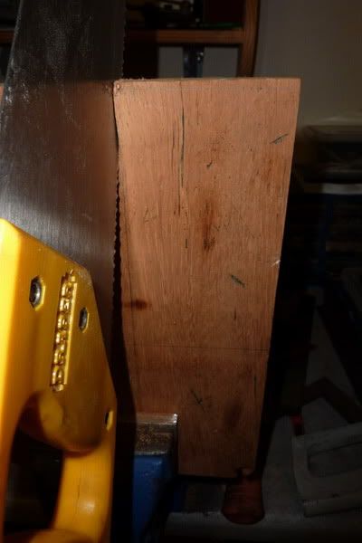
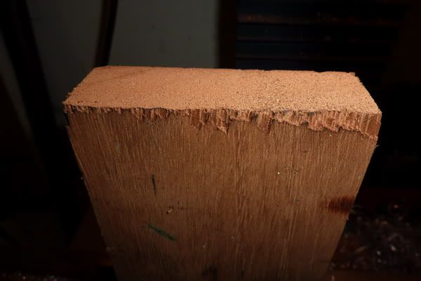
Time to get some (as Bogs would call it) brown stuff out. This is the point where all my hard work is spoilt by not being able to make things out of wood! I spend about 0.1 seconds searching for the right bit and found this lovely bit of, well, wood. ???

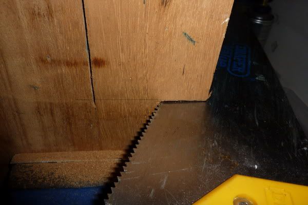
Hacked it into roughly a rectangular shape:

2011-01-2215-05-20_0001-1.jpg

2011-01-2215-06-45_0002-1.jpg


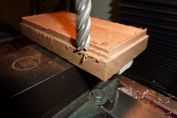
The saw just wouldn't cut it so to speak so transferred to a proper tool - yep, it's getting milled!

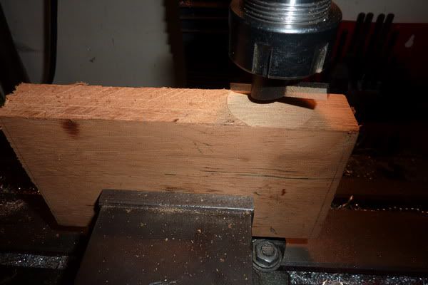
Flycutting to get it square:

2011-01-2215-11-45_0004-1.jpg


Then rotated around to do the end:

2011-01-2215-17-41_0005-1.jpg


At this point I realised that if I went one way with the flycutter it splintered one side, the other way it splintered the other! Problem was, I'd splintered alternate sides when flipped it over! :mad:

2011-01-2215-20-16_0006-1.jpg


Anyway, i'll live with it!

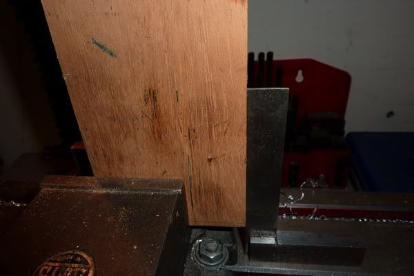
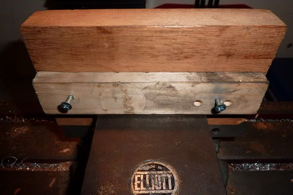
At this point I drew on some newly found knowledge (kind of) from Bogs' Scott Vacuum Engine post. Working with wood is a bit like castings at first, except it's easy to grip and machine- but nothing is square! I couldn't fit this bit in my vice and didn't want to move the vice so I screwed a batton on underneath to grip it with:

2011-01-2215-30-57_0007-1.jpg


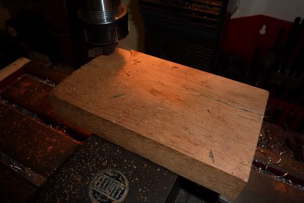
Cleaned up the top - I thought it was a bit thick anyway and this would at least get rid of the splinters on the top surface:

2011-01-2215-33-10_0008-1.jpg


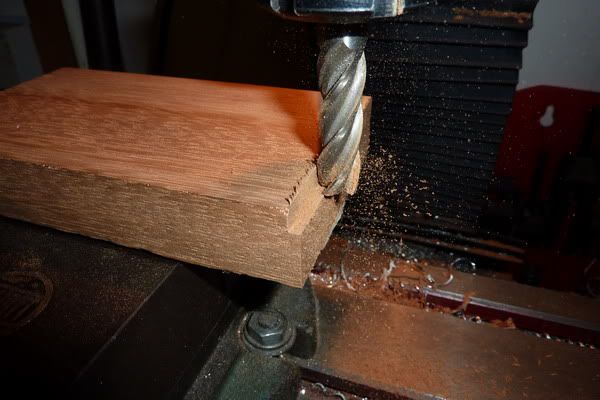
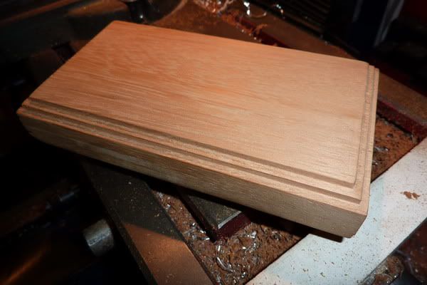
Started my masterpiece, a stepped edge no less! ;)

2011-01-2215-42-25_0009.jpg


Starting to take shape doing other sides:

2011-01-2215-50-23_0010-1.jpg


It looks a mess but these burrs come off with a few rubs of sandpaper by hand:

2011-01-2216-00-51_0011-1.jpg


Looks not too bad for me!

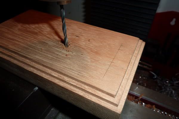
Marked up for engine mounting holes and drilled:

2011-01-2216-12-06_0012-1.jpg


The beauty of this is, you don't need to clamp, just position by eye and because the cutting force is low and the bit of wood relatively large you can just hang onto it and quickly drill through.

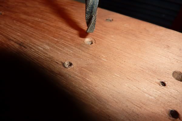
Turned over to counterbore the holes as the 6ba screws aren't long enough to go right through.

2011-01-2216-19-33_0013-1.jpg


That's the base nearly finished. Now onto the burner.

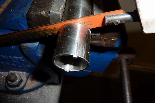
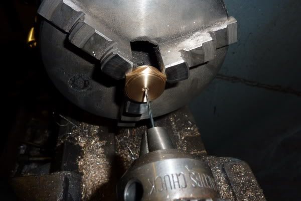
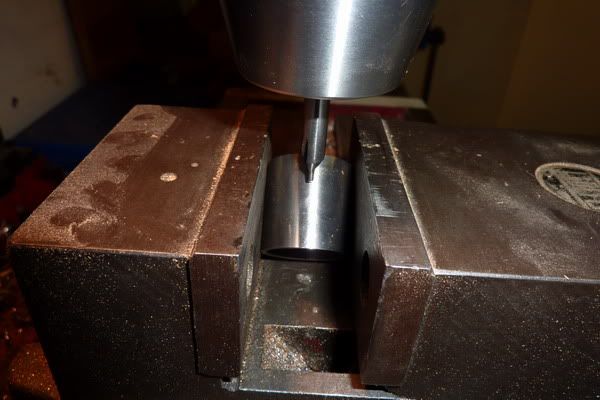
I found a bit of (I think) stainless tube that I got given at work:

Cut to length after facing, then other end was faced:

2011-01-2216-31-57_0018-1.jpg


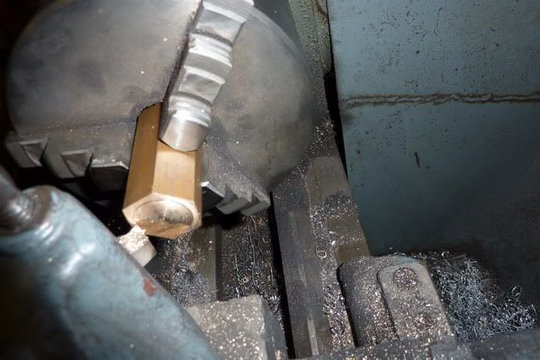
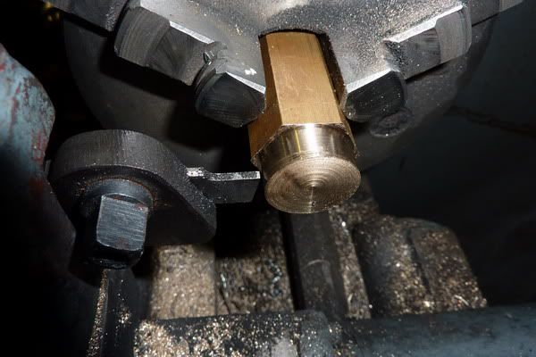
Then found some brass hex just right size for lid and base:
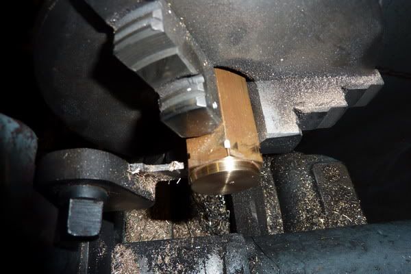
Facing off:

2011-01-2216-49-01_0020-1.jpg


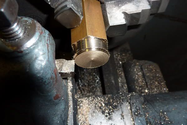
Turning down to size - I overestimated how much needed to come off so had to go again!

2011-01-2216-53-47_0021.jpg


2011-01-2217-00-10_0022-1.jpg


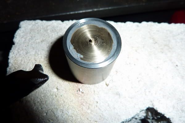
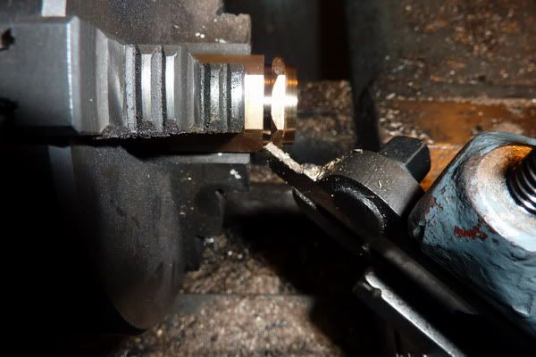
Parting off for the base, this was to fit inside the tube and be soldered:

2011-01-2217-09-27_0014-1.jpg


Ready to solder in, I would just soft solder this as it shouldn't get hot enough to melt and doesn't need any massive strength, just be leak proof. I use this soft solder paste as flux that I found in my grandad's garage for soft soldering. Seems to work well, only thing is, it gets solder wherever you put the paste. Doesn't need to be too neat this though as underneath:

2011-01-2217-23-23_0015-1.jpg


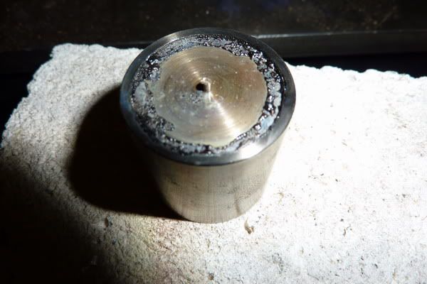
Heated up and a bid more soft solder fed in:

2011-01-2217-25-29_0016-1.jpg


This didn't work. It's stuck to the brass but hasn't taken to the tube whatsoever. So all this had to be cleaned off. ??? :-\

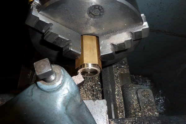
I decided to continue and make the cap while I had a thought how to stick it together:

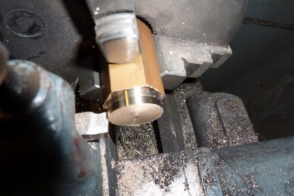
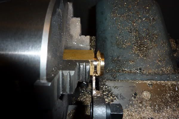
This just needed a slightly smaller dia than the base for a sliding rather than push fit:

Still in the lather from before so it was faced and skimmed down to size:

2011-01-2217-43-26_0023-1.jpg


Then partly parted off:

2011-01-2217-50-49_0024-1.jpg


At this point I came over a bit funny and heard a voice in my head about artistic license! I would apply a little here, wouldn't recommend this but I just took very light cuts to give a chamfer:

2011-01-2217-54-08_0025-1.jpg


Then parted off but leaving a couple of steps:

2011-01-2217-57-05_0026-1.jpg


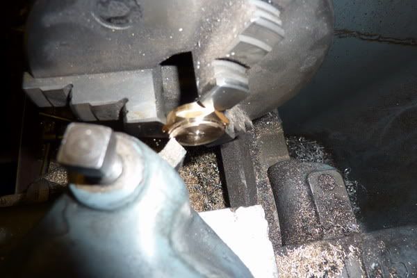
I sawed through the last bit as things were a bit close to the chuck for my liking so flipped it around and faced:

2011-01-2218-35-13_0027-1.jpg


Then just centre drilled and drilled through for an air hole:

2011-01-2218-39-52_0028-1.jpg


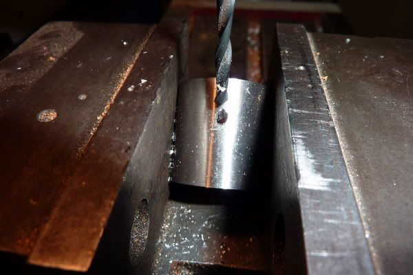
At this point I decided to put the angled wick tube into the side of the tube to get the correct height rather than into the cap as I had done with my Jan Ridders Flame Licker. So I set about drilling the angled hole. I just gripped in vice with the base half way up for support:

2011-01-2218-59-45_0030-1.jpg


I wasn't sure how to set the angle but then remembered I got a digi angle gauge for xmas which I hadn't used yet. Luckily it just fit between the jaws so I knew that for the first time, an angled thing of mine was about right!

Gradually opened up to 1/4" dia to accept some copper tube I had found:

2011-01-2219-01-52_0031-1.jpg


I had decided I would silver solder the base and wick tube in now - but that didn't work either. It just wouldn't take to the steel for some reason. I was sure I'd silver soldered stainless before, or at least seen it done? :eek:

So even more of a mess had to be cleaned off now. I was mulling over what to do and decided that being as I had a good fit on the parts, I would loctite them together. Don't know whether it will work long term or not, I was going to use some epoxy glue like araldite but I didn't have any and didn't want to wait for ages for it to dry.

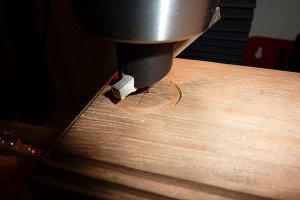
Can't find a pic of the completed burner but I went on to finish the base. I wanted to put a good fitting recess in it so as the burner would be positioned in the right place and the speed could be varied by rotating it within that recess. It would also stop the burner sliding about with vibration.

I was going to do this in the lathe but my lathe doesn't have a gap bed and couldn't quite swing it. So I thought I'd use the milling machine.

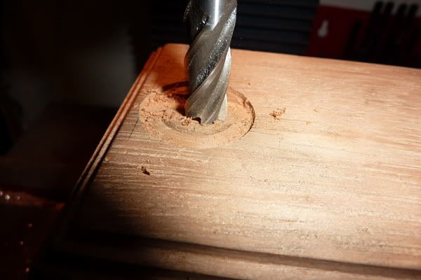
I have no boring head so I used the flycutter to outline the recess / sort of trepan to depth:

2011-01-2221-45-50_0032-1.jpg


Then used an end mill to carve out the middle to the same depth. This was tricky, kept forgetting which way my hands were turning if that makes sense! :big:

2011-01-2221-51-55_0033.jpg


I should have used the biggest end mill I had but never thought at the time.

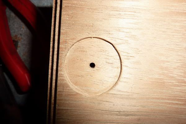
Here you can see I went over the lines a little in a couple of places but not too bad:

2011-01-2221-57-30_0034.jpg


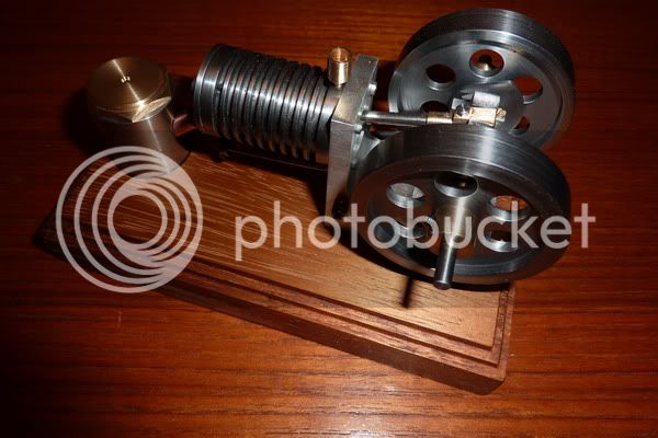
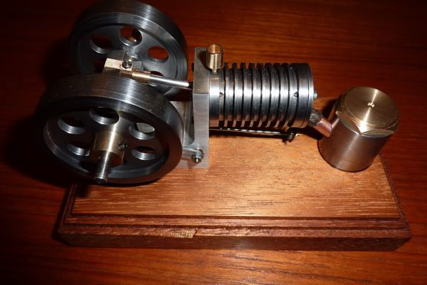
The brown stuff then had some more brown stuff rubbed onto it (teak oil) before the engine and burner were put into place.

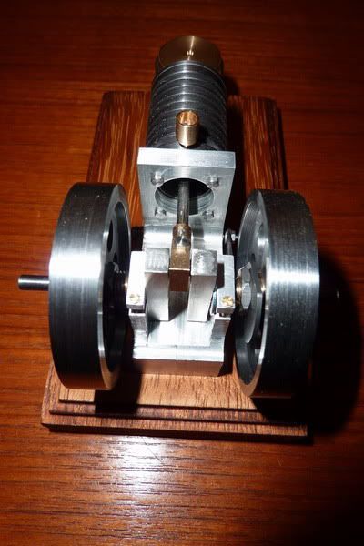
Here is the finished engine no.1. I should have mentioned, since this is my dad's present, I decided to just put some emery cloth and oil on the flywheels to stop them going rusty rather than paint them:

2011-01-2222-18-59_0035.jpg


2011-01-2222-19-08_0036.jpg


2011-01-2222-19-19_0037.jpg


2011-01-2222-19-30_0038.jpg


I took a couple of videos last night but the engine kept running away with itself and getting a bit of valve bounce, then the valve would stick. So I had a slight adjustment to do giving it less valve overlap (as per instructions, I just didn't think it mattered before, but guess they are there for a reason!) today and took this video. Apologies if you can hear kids messing around in the background, this was just before a trip to mother in laws ;)

[ame=http://www.youtube.com/watch?v=pMfmtRP4OPc]http://www.youtube.com/watch?v=pMfmtRP4OPc[/ame]

As I said, I'll be having a short break from the workshop now, catching up on other peoples projects and getting back in the wife's good books before finishing off poppin no.2! She's feeling a little neglected over the last couple of months with me being in the workshop a lot! :-[

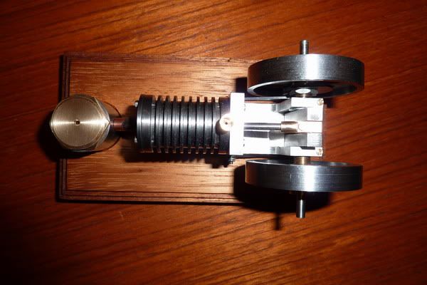
p.s. Just noticed that in those photos at the end, it looks like the engine overhangs the wooden base. It doesn't it's been carefully measured to ensure there is a nice border all around it. I've got OCD when it comes to things like that! :lol:

Also, the pic of the stainless tube, must have been sawing it off before I'd faced the end, think I was sick of showing pics of facing off!

Nick
 
The Base turned out Great Nick!

Well Done Thm:

Kel
 
Cheers guys, quite pleased with it, just wish I'd finished the other but it was taking awhile doing 2 of everything! Will get onto it after my break!

Nick
 
Nice job on the base and burner both Nick. Enjoy your break!

Bill
 

Nice job Nick. Looks and runs great!
 
Thanks Bill and Kevin,

Will do, will give my hands a chance to recover, bags under eyes to fade and head to be void of engine parts spinning around in it!

 
Hi Nick, thanks for the write-up, I only discovered these pages a couple of days ago so was a bit lucky to come in at the end. You did a great job & it looks & runs really nice. I found the site as I was looking for info on Jan Ridders flame sucker that I have just built but doesn't run. BTW what fuel do you use? Looking forward to more of your projects.
Regards from Ian S. (Down Under)
 
Hi Ian,

thanks for the comments. On this engine I just use any methylated spirits, it's a bit more forgiving, but on the Jan Ridders Internal Valve engine I made, it's much more tempremental - I bought some Industrial DNA (Denatured Alcohol) = Industrial Methylated spirits which burns cleaner. It would run on the other stuff but not as well and those engines need all the help they can get! Is that the Ridders version you built? Most people that have built them have had trouble getting them running but a few builds on here have got there in the end through perseverence!

Shout up if you need any help with that, I will try to give some pointers.

Nick
 
Hi Nick, thanks for the info on meths & also the offer to help. Ivé tried meths, white spirits, a product called 'Shellite" it's designed for lighters & camp stoves, but I found it pretty oily, also tried methanol. I priced denatured alcohol & at $38.00 for 1/2 a litre it can stay there. I think the problems are two fold (the piston & valve fit fantastically, if you hold the cylinder vertically & lift the piston out, the valve follows it & flies out of the bore.) I think that the flame is not big enough, too small a wick & the flywheel bearings are not free enough. these things don't have much spare power. I have bought a cotton floor mop so have enough wick to last a life time. I'm going to redesign the con-rod so tht it has a split big end & then make up a one piece crankshaft with cone bearings each end. If it works o.k. I will make up little siver steel cups to press in each end of the crankshat & silver steel pointed screws, all hardened. But not for awhile as I'm still building the new workshop. I just built the engine to have a break from installing machines & cupboard building. I will post the success or otherwise when I'm done.
BTW, where abouts are you? I'm in a little country town about 75 Kms south of Adelaide.
Ian
 
No worries. I'd go with the meths out of those. Yes, friction is very very critical on that engine. The flywheel should run in its bearing for many revolutions, maybe 30 seconds on its own, and without the valve in, but the crank connected with the con rod and piston it should run for at least 20 revolutions. Jan has a pretty good troubleshooting section on his site for this but I couldn't achieve his requirements for friction!

You do need a huge flame (pay attention to jans site - the wick and flame position is literally the only place it will run in! My wick was a couple of mm thinner than he suggests and I think that affects it.

My conrod seems to work well, mine has a little more slop in it but it helps reduce friction. One guy at a show came up to me as he couldn't get his running. It was very well made, much better than mine but beceause it was so well made I noticed a tight spot with his piston rod. If that is all not aligned perfectly you will get a tight spot, hence the clearance in mine. Another thing that's a must is the hole in the valve - you want about 0.5mm or so clearance in there or it will cause the valve to bind slightly as the rod pushes it back and forth. the piston and valve should drop through the cylinder under their own weight.

My final point is controversial but works for me - put some thin, synthetic engine oil on the piston and valve - it just gives mine that last bit of perfect sealing it requires and stops the products from the combustion adhering to it which causes excessive friction and stops it.

I don't use oil on this poppin engine as it has a graphite piston but note the original plans have an oil cup. ;)

Your crank / conrod idea sounds good.

I'm in a place called County Durham in England, nearest big city that you may have heard of (doubt it!) is Newcastle, then York or Leeds. Did you get hit by the flooding? Hope all is ok.

Nick
 
Not sure whether you saw my Jan Ridders version but here is a vid incase you can get anything from it.

I just like watching it too! ;D

[ame=http://www.youtube.com/watch?v=z0GIegp_ZD8]http://www.youtube.com/watch?v=z0GIegp_ZD8[/ame]
 
Hi Nick, thanks for the reply & vid link. I will get the engine running 1 day. I have spent quite a while in your part of the world, lot's I could talk about but this is not the place. At least you are close to Harrogate, great exhibition. Great train museum & great national coal mine museum & great city wall to walk around. Cheers, Ian.
 

Latest posts

Back
Top