
You are using an out of date browser. It may not display this or other websites correctly.
You should upgrade or use an alternative browser.
You should upgrade or use an alternative browser.
'Poppin' Flame Licker Engine
- Thread starter NickG
- Start date


Help Support Home Model Engine Machinist Forum:
This site may earn a commission from merchant affiliate
links, including eBay, Amazon, and others.
Haha, thanks Steve, just need to keep up some momentum now. Think I'm going to finish bits off that actually let me fasten things together to give me some inspiration - always better as it starts to resemble an engine for me!
Jamie, I think Rick on here tried a graphite piston and had good results so fingers crossed. Shouldn't need any more lubrication either then.
Nick
Jamie, I think Rick on here tried a graphite piston and had good results so fingers crossed. Shouldn't need any more lubrication either then.
Nick
Didn't get much done tonight, was basically messing around but nevertheless did a few jobs that needed doing.
I cut the shaft away from middle of crank, drilled and tapped the holes in the base, tapped the holes in cylinder to mount and for cover, drilled and tapped the hole for the oiler, cut some bolts to length and assembled some bits.
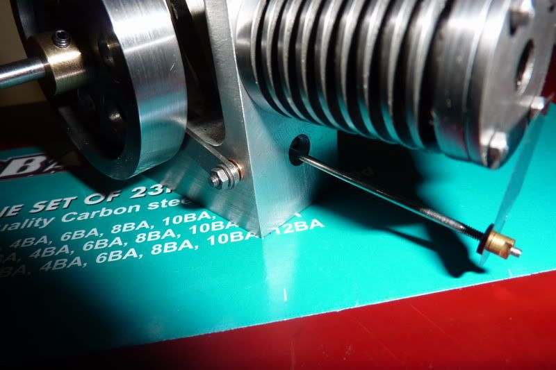
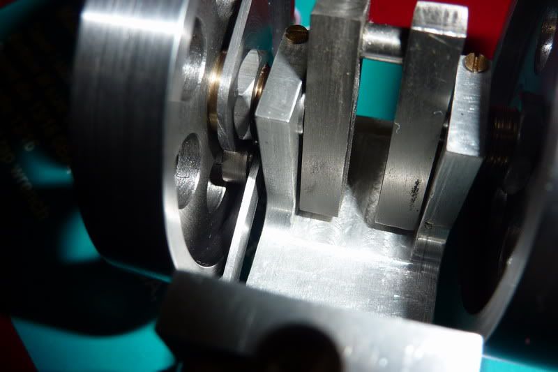
Here are a couple of pics of the assembly. It's only now that I get a feeling for the size. I love the look of the engine but the more I look at it the more I realise it's not particularly well made. I just really hope it's going to work! Will just have to make sure I get all the critical bits right again.
Quiz night at the pub with mates tomorrow so there won't be any progress until thurs night now, hopefully i can crack on and get some bits made now some of those fiddley jobs are out of the way.
Nick
I cut the shaft away from middle of crank, drilled and tapped the holes in the base, tapped the holes in cylinder to mount and for cover, drilled and tapped the hole for the oiler, cut some bolts to length and assembled some bits.
Here are a couple of pics of the assembly. It's only now that I get a feeling for the size. I love the look of the engine but the more I look at it the more I realise it's not particularly well made. I just really hope it's going to work! Will just have to make sure I get all the critical bits right again.
Quiz night at the pub with mates tomorrow so there won't be any progress until thurs night now, hopefully i can crack on and get some bits made now some of those fiddley jobs are out of the way.
Nick
- Joined
- Jan 19, 2010
- Messages
- 1,193
- Reaction score
- 41
Great progress Nick!
When I built the Double Poppin I used graphite for the pistons. It works great, never have to lube, and the cylinder does not need frequent cleaning.
The biggest thing to get right on this engine is the valve. I have had more problems solved by tweaking the valve than anything els. If you don't have the material for the valves yet I would suggest stainless steel. I am using regular steel shim stock, (002") and the valves tend to rust due to the moisture that gets stuck to the valve when the engine is warming up.
I think you will find this engine much easier top get running than the internal valve Jan Ridders design.
Kel
Kel, thanks for the reply.
I'm a bit annoyed with some of it. My bolt ring didn't line up because I didn't use a robust enough method to position the holes so had to mess on filing holes etc. As it is, think you can just see in the pic, the threaded holes in cylinder aren't straight. Where the drill breaks through into the groove it must have pushed them out of line.
I will try the piston from graphite then if the bit I have is thick enough. Did you do it to drawing from graphite or modify it? I was thinking of just having a solid piston of graphite with a slot milled in it and a cross hole instead of bothering with the yoke, but when I tried that in cast iron on the Internal Valve one it didn't work - but that may have been because the fit wasn't good enough or the weight was too much. Graphite is lighter anyway.
For the valve I was going to cut the end off a feeler gauge as that's all I have so not sure if that is stainless. What I was thinking though, is putting a button of graphite on the shim so that is the valve - do you think that'd work? might have to extend the rod by thickness of button. The Bruce Engineering flame gulper has a graphite valve but it's pulled onto the face by springs.
Nick
- Joined
- Jan 19, 2010
- Messages
- 1,193
- Reaction score
- 41
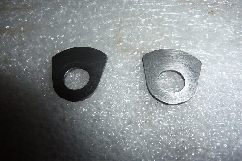
Nick, I have attached a drawing of the graphite piston assembly.
There is three parts to make.
1. The piston. It must be made a little shorter than the plan to leave room for the washer on the top. Threads dont work that great in graphite. This design sandwiches the piston between the yolk and a washer on top with a screw through it.
2. The yolk, I made a flange on the end to create more surface area for the sandwich affect.
3. The washer. Smaller than the piston diameter, and thin enough to clear the cylinder head.
I am not sure a wrist pin hole would hold up, built into the graphite, but I have no experience with that, so I really can't say.
Kel
fcheslop
Well-Known Member
Hi Nick,I also used the end of an old feeler gauge worked no problems
best wishes Frazer
best wishes Frazer
Thanks Kel and Frazer, that will be a great help when I get that far!
Am going to leave the piston until last as I think there's a fair chance I will need to make more than 1, also you can get a better feel for the friction when you have the rest of the components done and can actually spin it over.
Thanks, hopefully not too long now KustomKB, still planning for next tuesday finish so that's bound to fail!
Nick
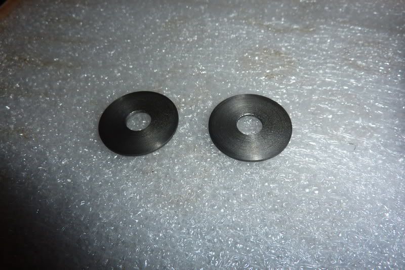
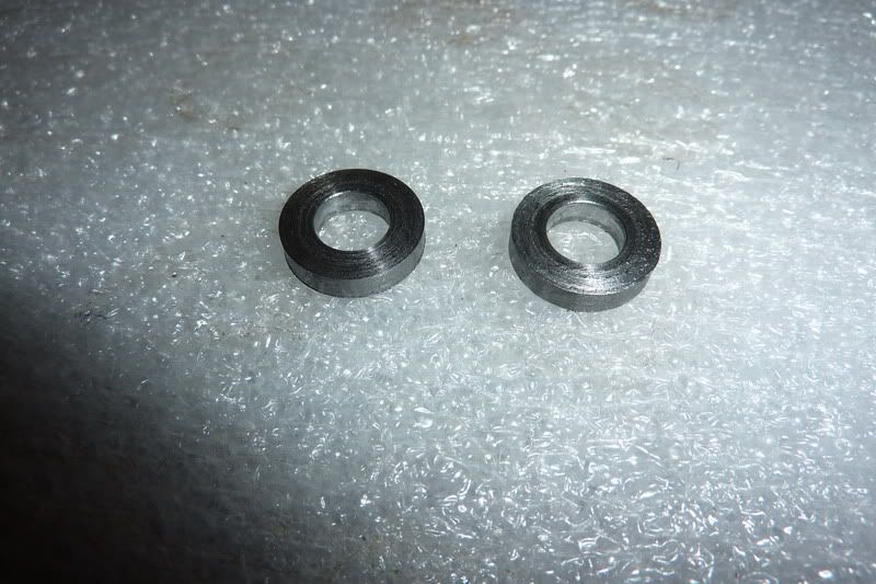
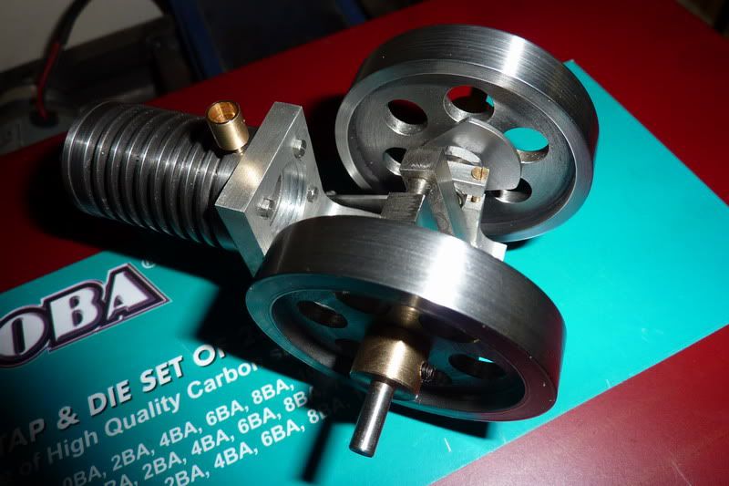
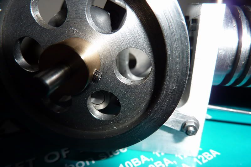
Got done what I planned tonight. Made the flywheel bosses, nuts and washer. Started off really slowly, didn't have material to hand, had to find right sized drills, swapping tools around etc! I did start taking pics of machining operations but then realised they were all straight forward, nothing people haven't seen 1 million times before so stopped to get on with it.
Here are the finished components:
and assembled onto the engine:
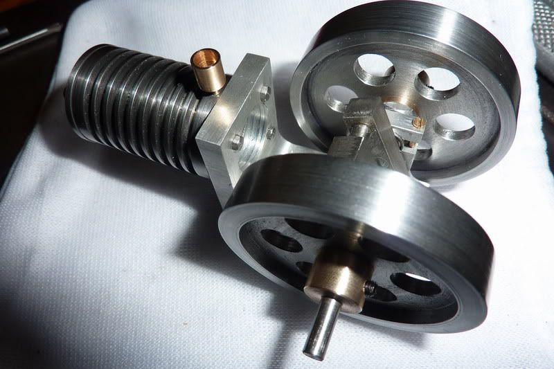
The crank is very free running, those two flywheels combined are actually quite heavy. 1 of the flywheels is spot on but the other has a very slight wobble for some reason! :doh: Nothing too bad though.
Still lots of parts to make yet, wish I'd never started making two of them! I think I've said before I won't make 2 of anything again!
Nick
Here are the finished components:
and assembled onto the engine:
The crank is very free running, those two flywheels combined are actually quite heavy. 1 of the flywheels is spot on but the other has a very slight wobble for some reason! :doh: Nothing too bad though.
Still lots of parts to make yet, wish I'd never started making two of them! I think I've said before I won't make 2 of anything again!
Nick
I decided I'd be a good husband and stay in with the wife on Friday night - actually I was knackered but she doesn't need to know that! :lol:
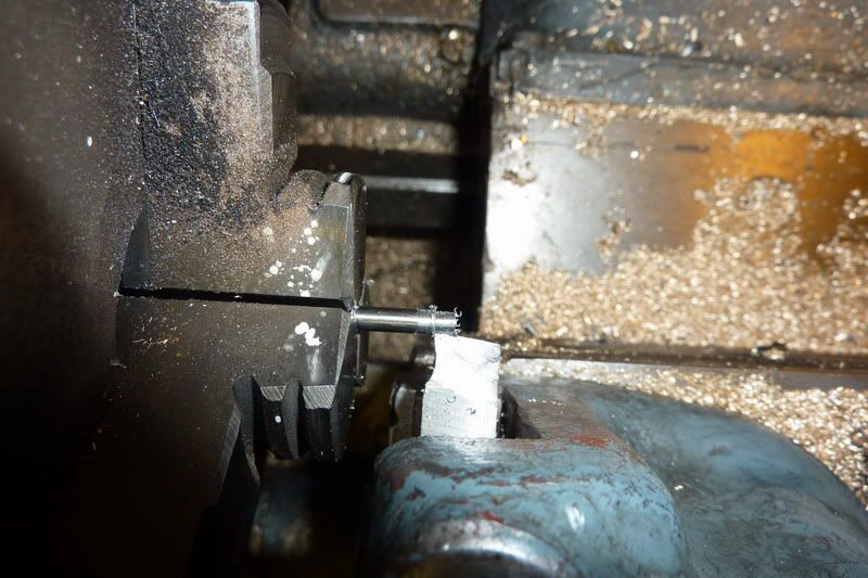
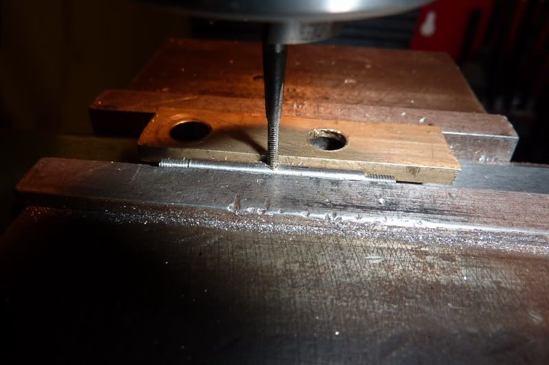
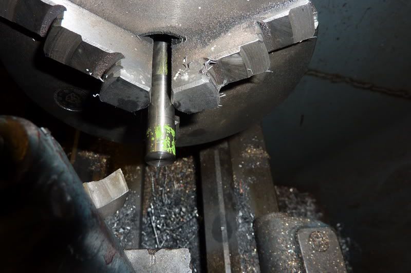
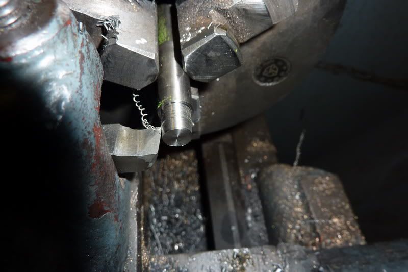
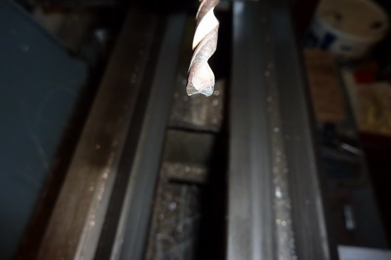
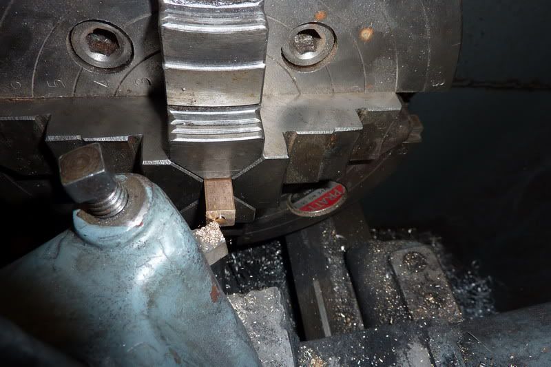
Started making the valve rod. This was just a bit of 1/16" stainless rod with a thread on each end. The thread, unfortunately had to be 10ba (bit small for my liking). 1/16" is too small for my lathe chuck to grip so I had a cunning plan, or at least I thought I did... hold it in the pin chuck:
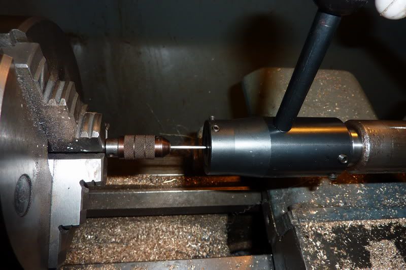
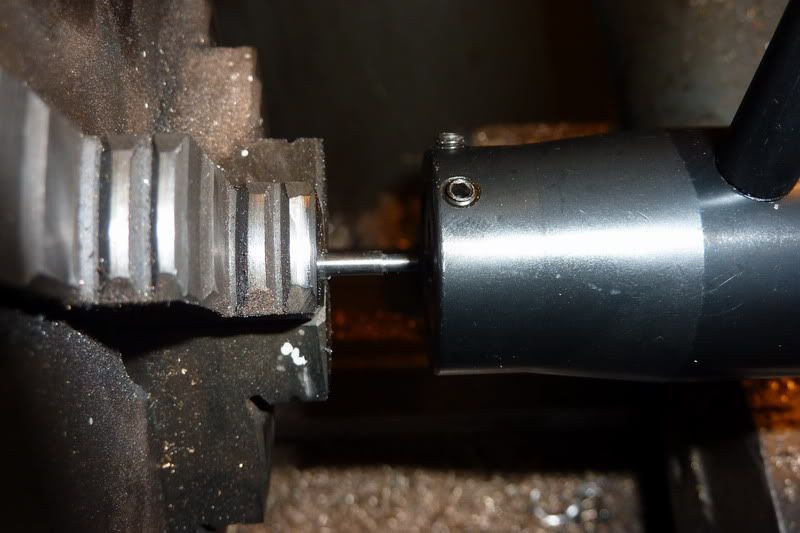
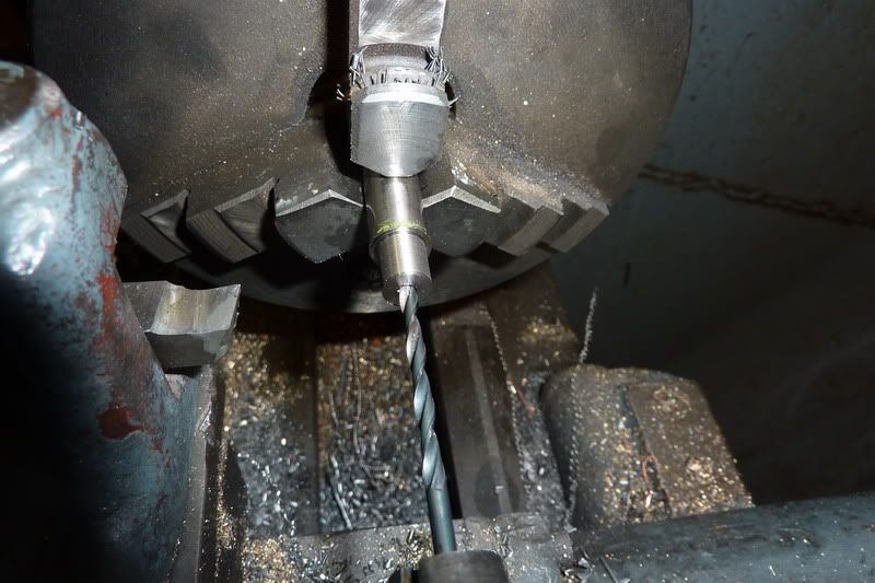
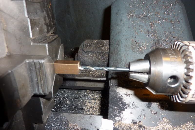
but this didn't really get a good enough grip. The collet was just too big so it slipped. So put the drill chuck in the headstock:
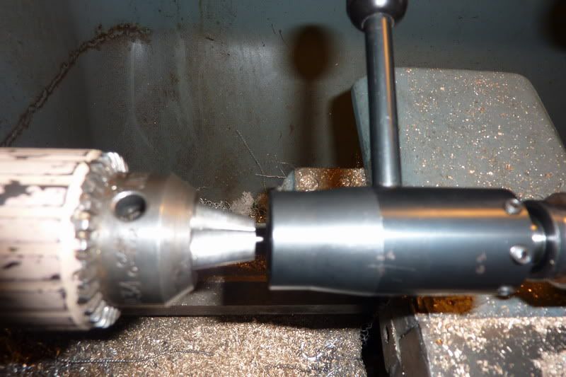
Worked this time. My new Soba 10ba die from the set I got for christmas didn't seem to be working very well though so used an old presto one and that worked!
Using 10ba also meant that I didn't have any nuts. I found one then had to drill another out that was even smaller!
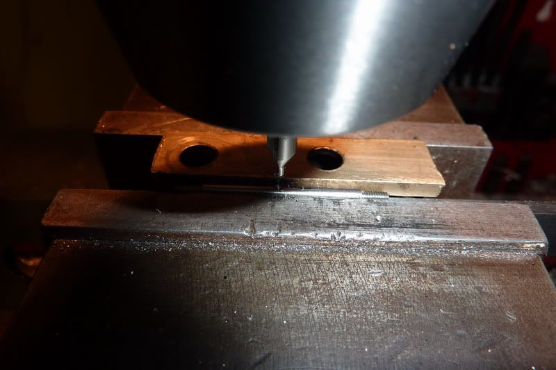
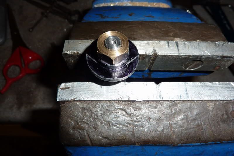
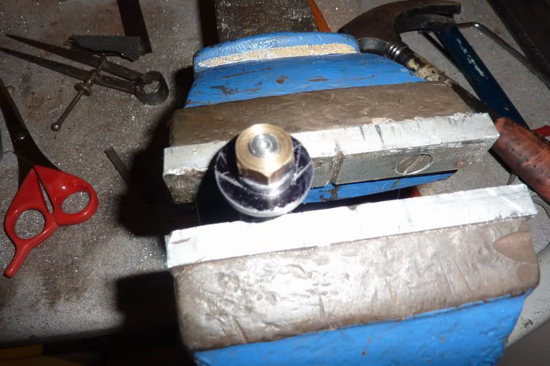
Tapped in vice as couldn't feel what was happening in lathe:
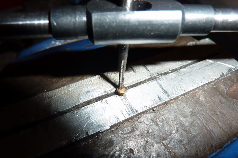
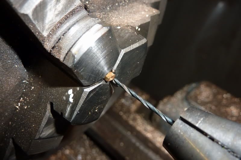
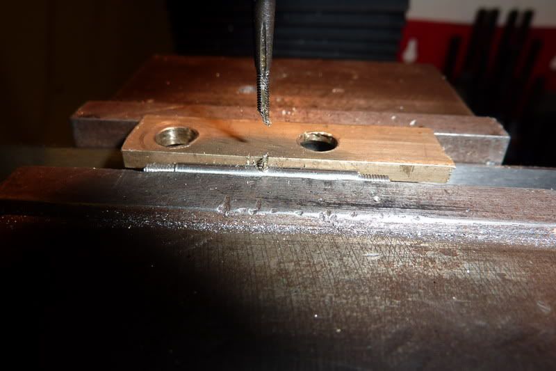
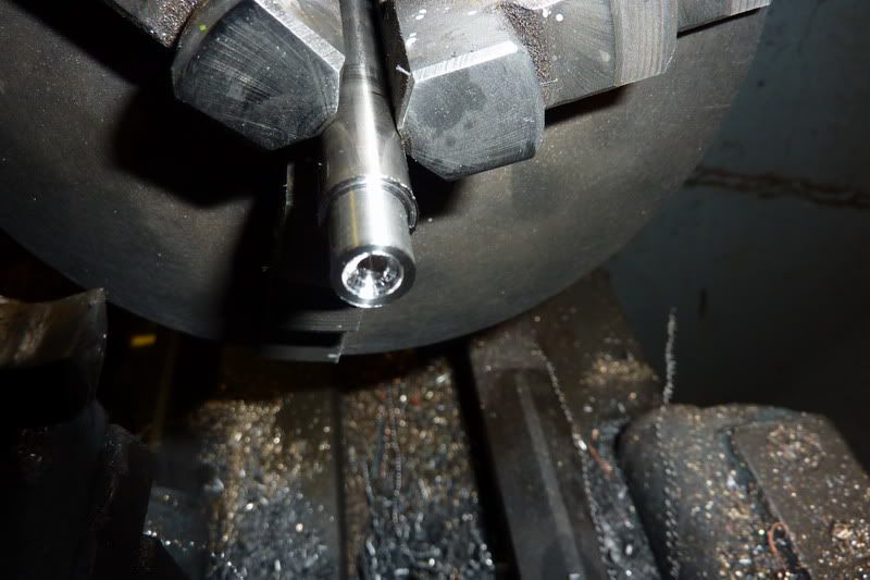
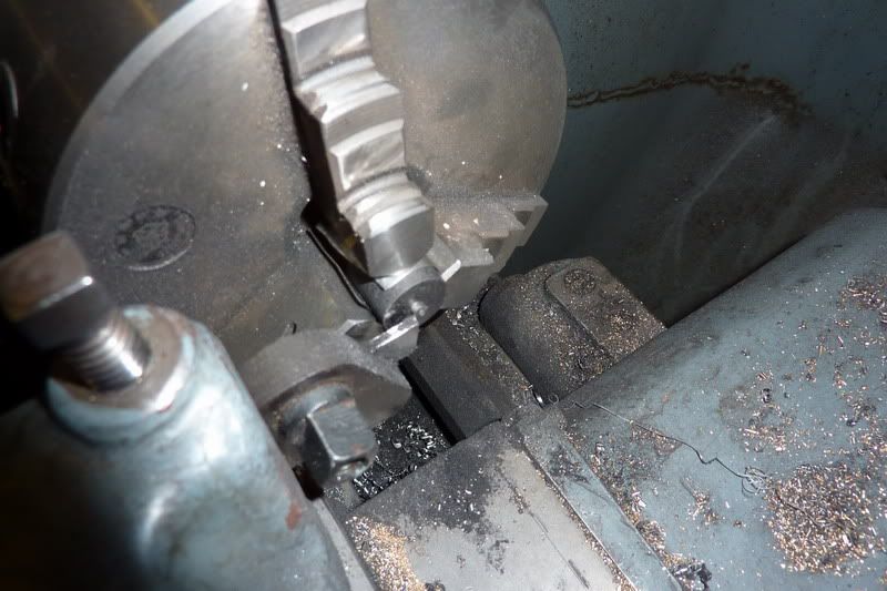
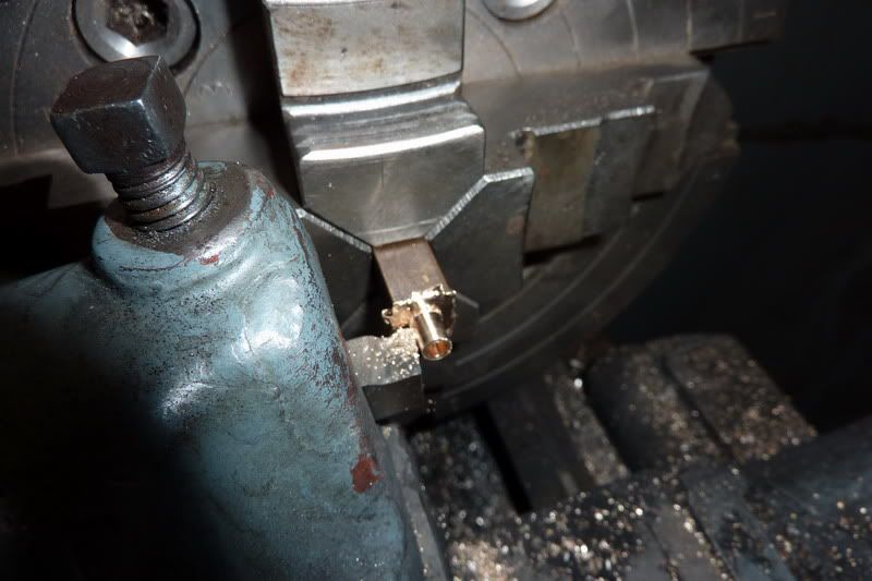
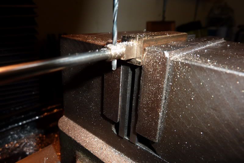
The next thing to make was the valve rocker shaft. This was from 1/8" silver steel. First had to turn ends down for 8ba:
Then cut the threads:
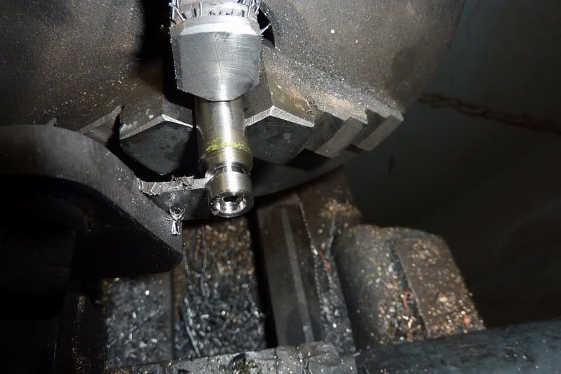
Then had to think of a novel way to clamp in the vice level - this is the heath robinson way I came up with, rested on a parallel and used a bit of packing in the jaw to grip. Here I am centre drilling:
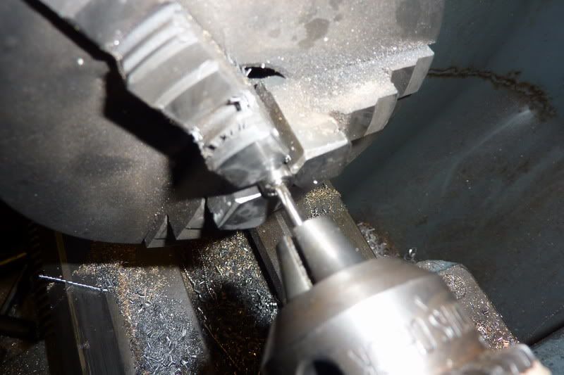
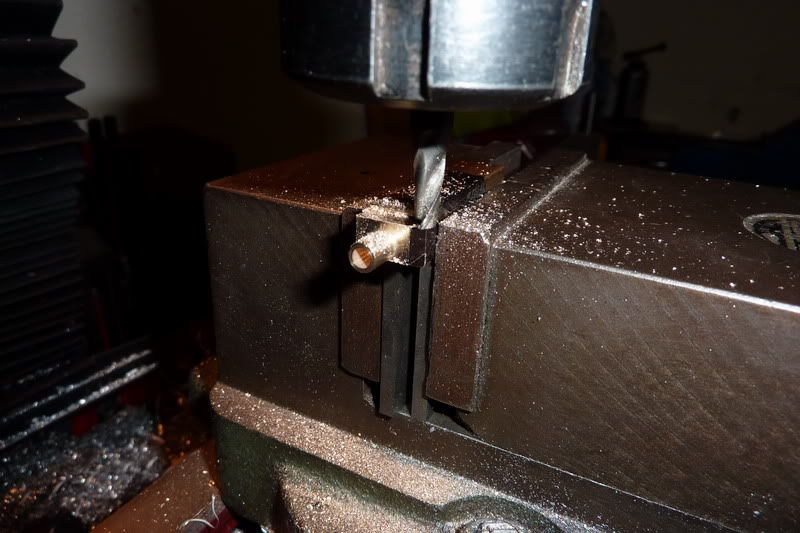
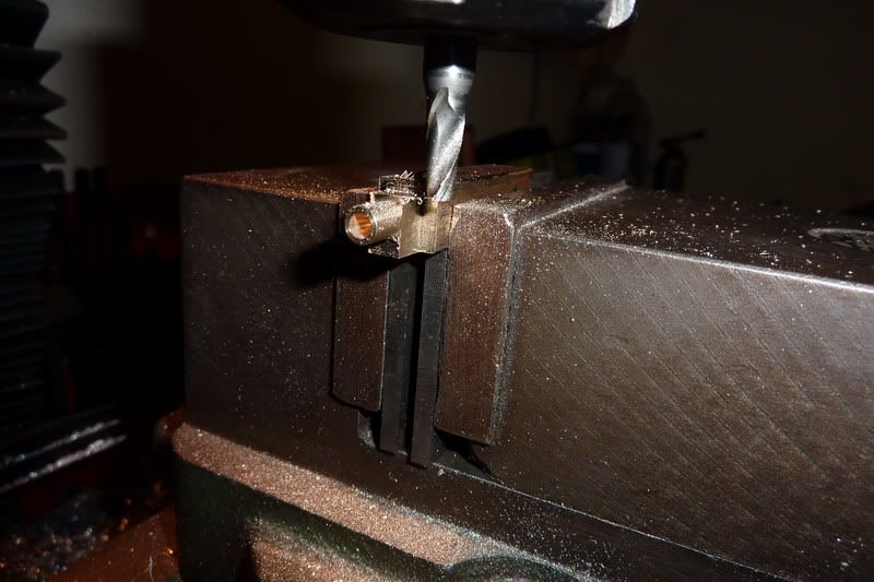
Seemed to work reasonably well, drilled out to tapping size and started tapping:
I was just thinking, this tapping lark in the milling machine is ok as long as use a low speed and oil and keep winding in and out... then ping!!!
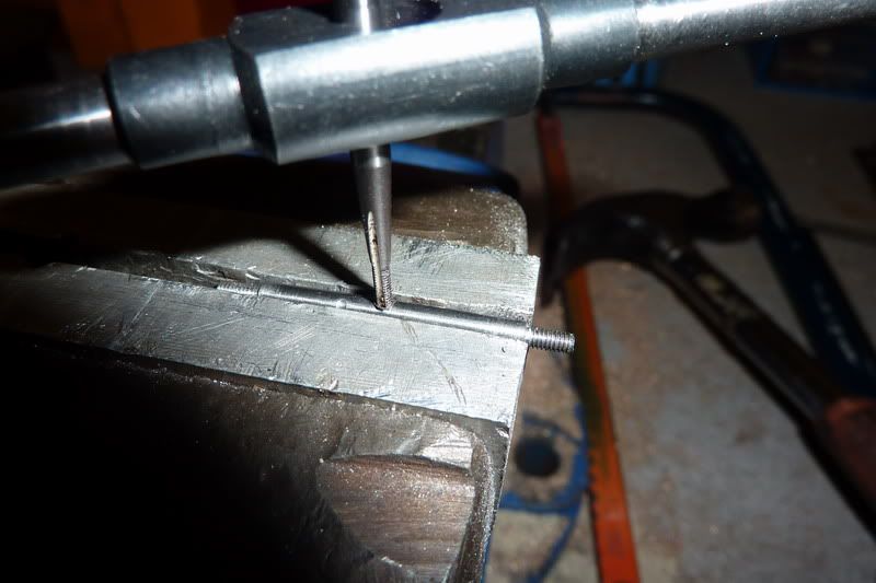
I don't really know what I was thinking, 10ba in silver steel under power? Really?! I started it off with the taper ok so I should have taken it out at that point to finish by hand but no, I had counted my chickens so to speak!
Luckily I managed to punch the tap out with a bit I ground off the end of the tapping drill. I thought I had a pic but can't find it. I had actually drilled it a size smaller to attempt to get a tighter fit so that won't of helped, but it helped save it. It had only tapped a couple of threads so I opened it up to the proper size and tapped again, I hasten to add in the vice this time!
This was before de-burring:
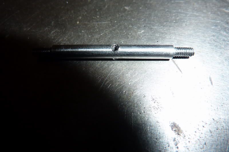
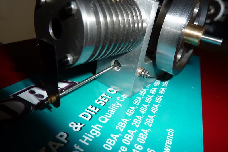
Assembled with rod and nuts:
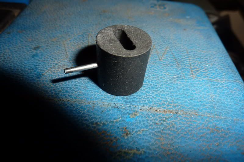
I then made the spring as was running out of time, that was nice and easy:
There's the assembly with the spring:
Forgot to mention that this was during the day on Saturday afternoon, I was allowed into the workshop for staying in the night before! The intention was to go back in later that night after watching a bit of silly sat night TV but I was too tired and only managed a bit. Did the valve shaft bushes.
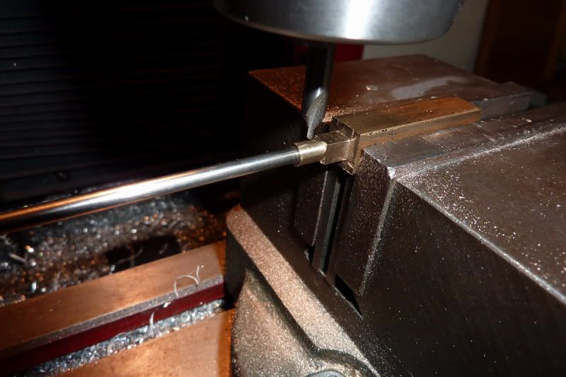
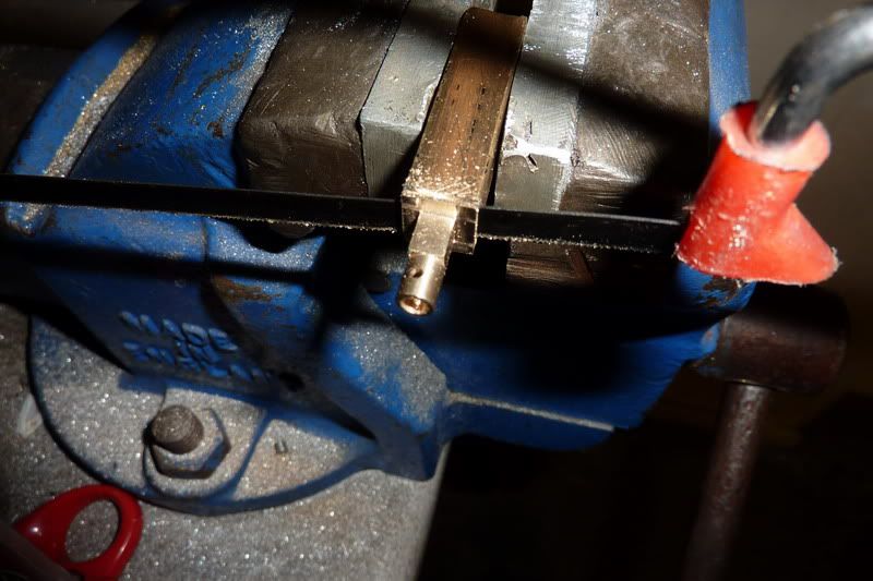
Drilling the rod. Think it's phosphur bronze but not sure, it came off a set of old scientific scales I think. It's sort of coppery and seems soft to turn? Anyway, it's the same stuff I used for my bushes on the ridders flame gulper.
Reaming 1/8" with my other christmas pressie:
Turning down to size. I wanted a light press fit, if too heavy it would crush due to thin wall and my 1/8" dia would be no more!
Finally parting off:

I thought the parting off was going badly as it kept leaving a pip (even though it was dead on centre) but luckily the pip just crumbled away and it was ok after a couple of twists by had with a countersink:
Then I tried the shaft in it and it was too tight! Then I remembered what Bogs told me about hand reamers having a longer tapered section, but I had reamed it blind so put it back in the lathe and reamed right through:
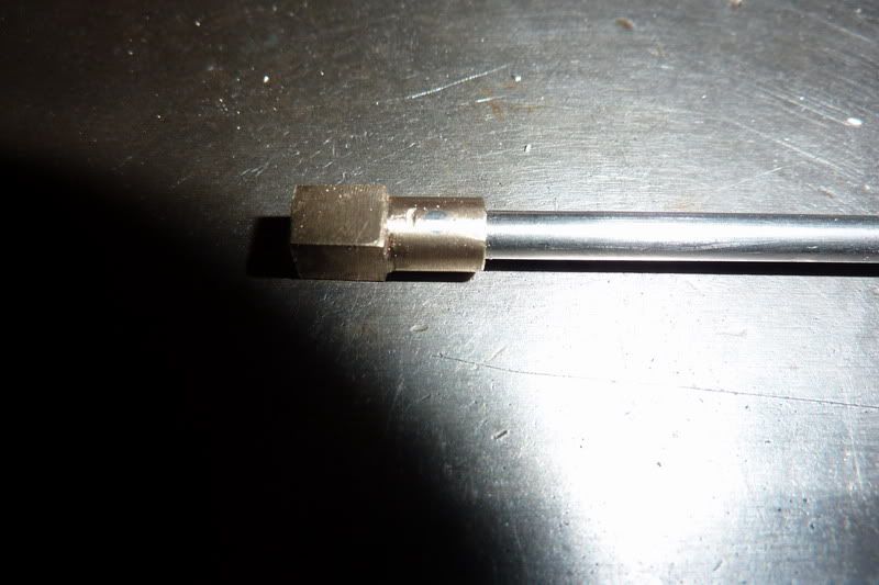
Another thing I noticed was that despite me being careful and using the graduated dial on top slide to make sure I parted off the right amount, it was coming out over size. I wasn't too concerned about this but when I started looking at the drawing, it was critical, the shoulder had to be 0.025" so that the shaft would protrude slightly at each end so I had to skim this down. Here is the finished bush:
Once I'd done the same for the other one, I'd had enough and quit while I was ahead. I just pressed the bushes in with a dab of loctite.
On Sunday I was allowed in the workshop during the day again ... what's going on? :scratch: !
So I set about making the cam(s). These are 1" diameter and 0.047" thick. I decided the best way would be to turn a bar to 1", drill, ream and part off. I had a little short length of cast iron I thought would be good as I know it's easy to part!
Facing off:
Turning to size:
Centre drilling:
opening up:
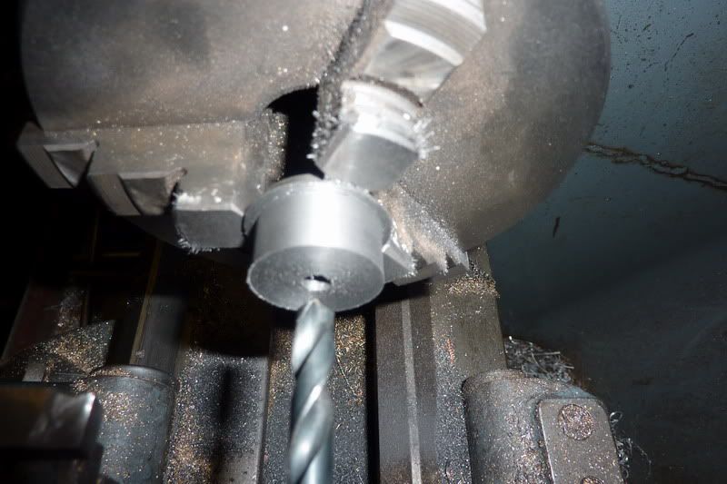
by the way, what do you leave on there to ream? Some people say make the reamer work, some people say just a smidgin ... I drilled 7.5mm for the 5/15" reamer I think and it seemed about right?
Reaming:
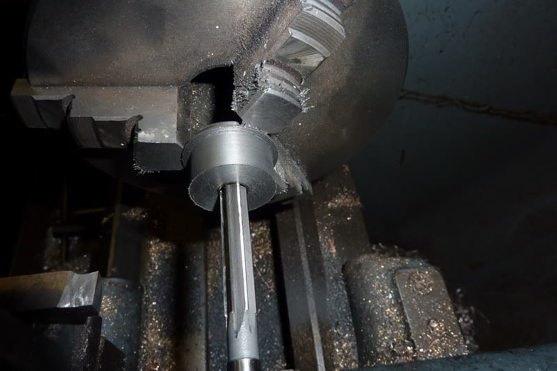
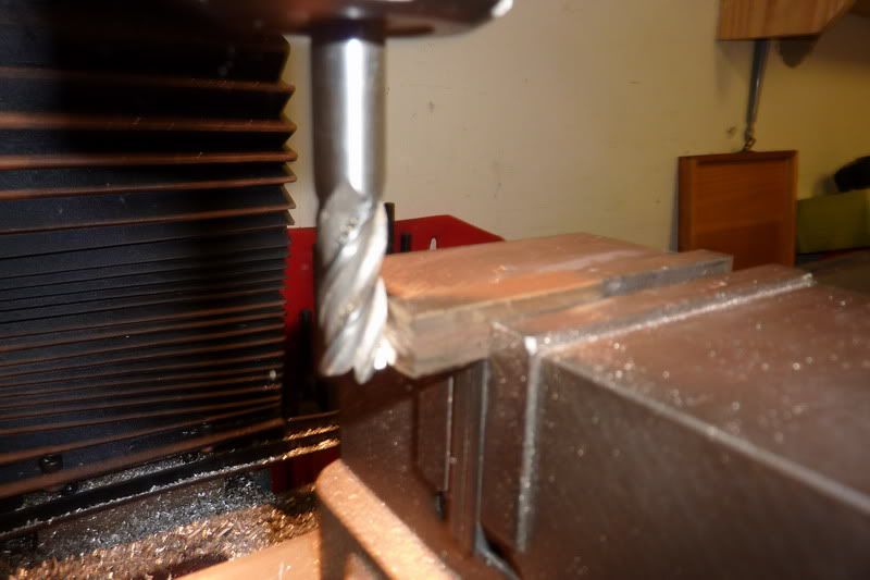
Then i set my parting tool up, looking from this angle I quickly realised you don't need to have much sticking out:
Parting off, used the centre as I wasn't gripping on much so remembered the advice from last time:
Here are the two blanks. One turned out 0.049" and the other 0.045" - oh well, think it'll do though!
The radii on the bottom of the cam was 0.300" so I set about making 2 filing buttons of 0.600" diameter with a 5/16" hole through the same. I took photos but just realised the entire operation was exactly the same as the cams, just from steel and a bit thicker! The only thing new was that it was the first time I've sucessfully parted steel :ddb:
I should have mentioned that I luckily remembered about the arbor I'd made for the flywheels which was the right diameter to hold it. With a bit of foresight, the od of this could have been made the same thereby incorporating filing buttons, but I had made mine from hex bar to index for the flywheel holes.
Here are the blanks mounted on the arbor with filing buttons and marked:
I thought, that looks wrong some how, and another look at the drawing confirmed that it was. The 110 degrees duration is shown in a funny way, so I interpreted what it meant and re-marked. You probably can't see it very well.
I thought I had a couple more photos but I can't find them. Anyway, I just hacksawed most of it away with junior hacksaw and filed the rest. The filing buttons didn't really work as they were just steel and not hardened but were there as a visual guide I suppose! I fear I may have taken a bit too much off so not sure whether the valve will be open long enough. Will see.
Sorry, it's a long post this ... need to update more frequently in future in bite sized chunks!
Next was the roller, pin and arm in that order.
The roller was from a bit of stainless steel:
Facing:
Turning to size:
Drilling:
I decided I'd have to grind a drill flat to square out the counter bore for the pin as didn't have a slot drill or end mill small enough:
Drilled with right sized drill first:
Then flat drill before parting off:
I tried to be clever when parting to give it the 1/64" step which sort of worked but I did my calcs wrong and it ended up too long anyway. Hadn't read drawing properly and added 1/64" to overall length. To that had to come off. Needed to ream it through anyway though:
Here are a couple of pics of the finished roller:
Parting the stainless was worse than the mild steel - tended to chatter a bit, prob had speed or feed wrong.
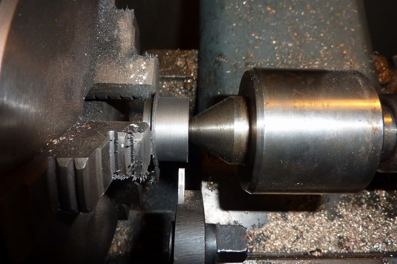
Onto the pin, simple turning job but had to be the right dimensions again.
Facing:
Turning bearing surface:
Turning pin:
Parting:
Finished:
Assembled into roller:
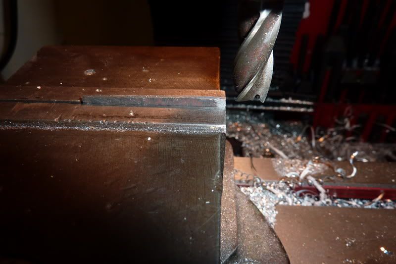
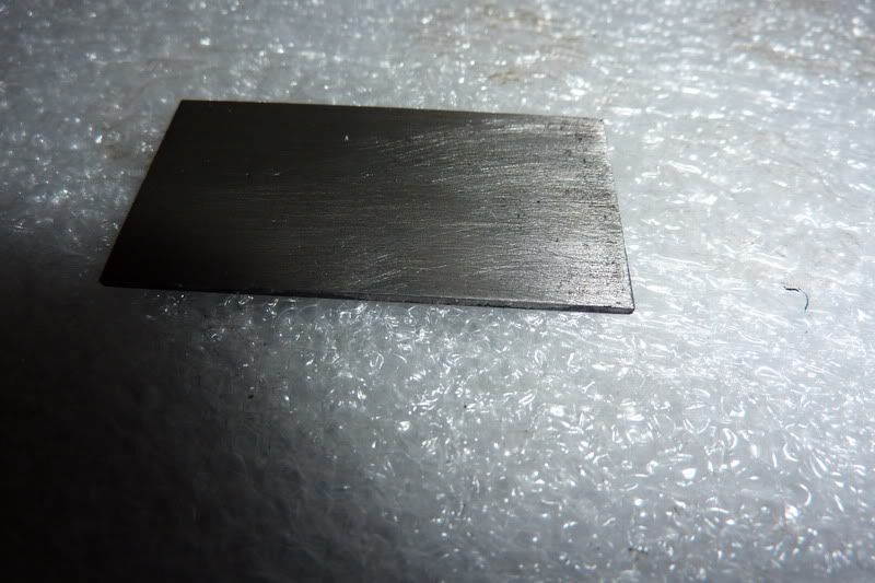
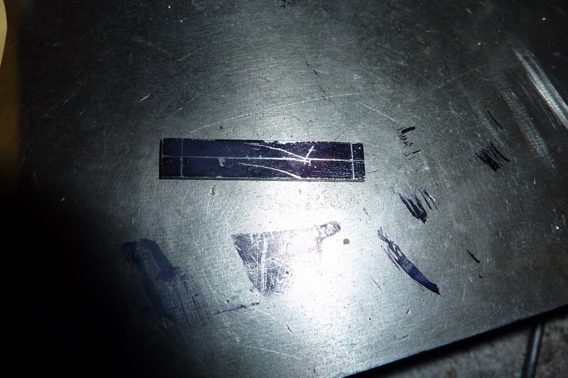
Now the arm, which would complete the whole valve assembly. I was going to use some 1/4" square bar, drill the holes and try to split it giving me 2 components but I decided that was destined to fail and I was making hard work of this. So I routed around and found some rusty steel sheet just the right thickness. Had a bit of straightening to do then cut a bit off.
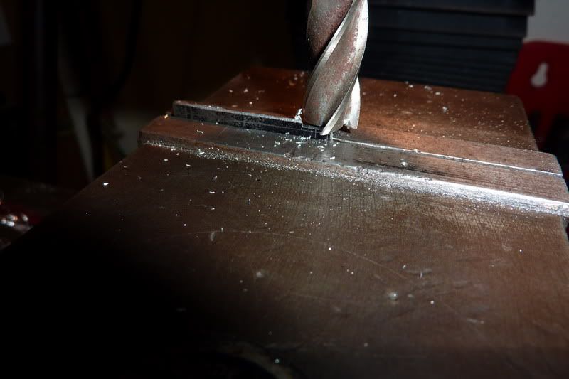
Squared up in milling machine:
Here it is:
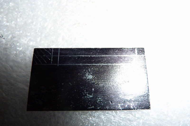
Marked it up:
Cut off and squared it up again:
Then had to re-mark it:
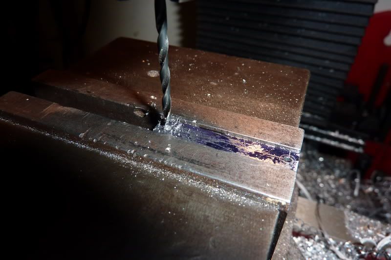
Drilled holes:
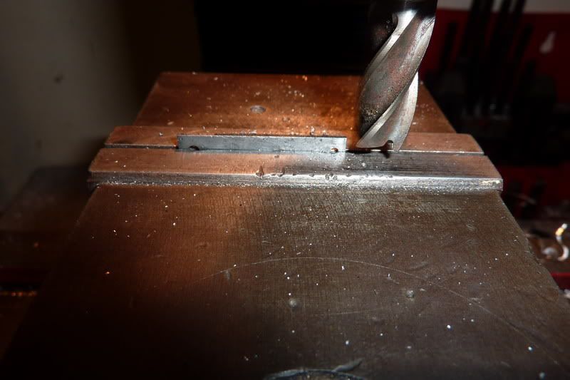
Then, by eye put at an angle in vice to mill angled sides. I didn't just do it willy nilly but thought I'd align the centre of the big hole and the bottom of little hole with the top of the vice jaw which would give the required offset.
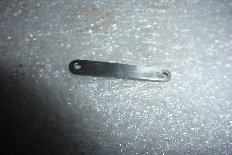
After a bit of filing, it worked pretty well:
Then assembled the pin and roller onto it:
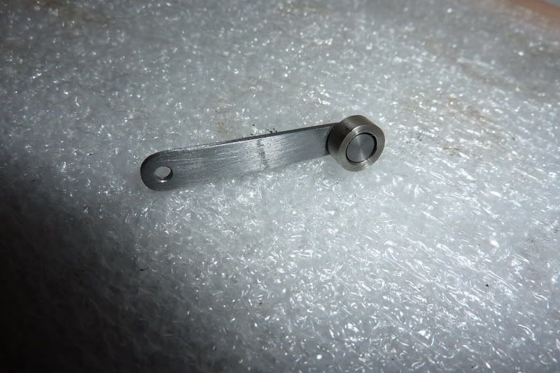
The idea was to peen over the pin, but without a ball pein hammer or rivet snap I had to use a nail punch, which worked well enough. I was really impressed with the roller, it spins over almost like a ball race but a bit looser. Probably due to the relatively hard metals it's made of.
That's about as far as I've got. Still on track, just the piston, rod & big end, burner and wooden base to complete. I've decided against the metal base (again!). I was going to make a brass one and machine turn it but I decided you can only see 3/16" all around so it's not worth it and it's pointless to boot!
Here are a few snaps of the assembled engine so far. What a fiddly job that was :lol: shame it's got to come back to bits! :doh:
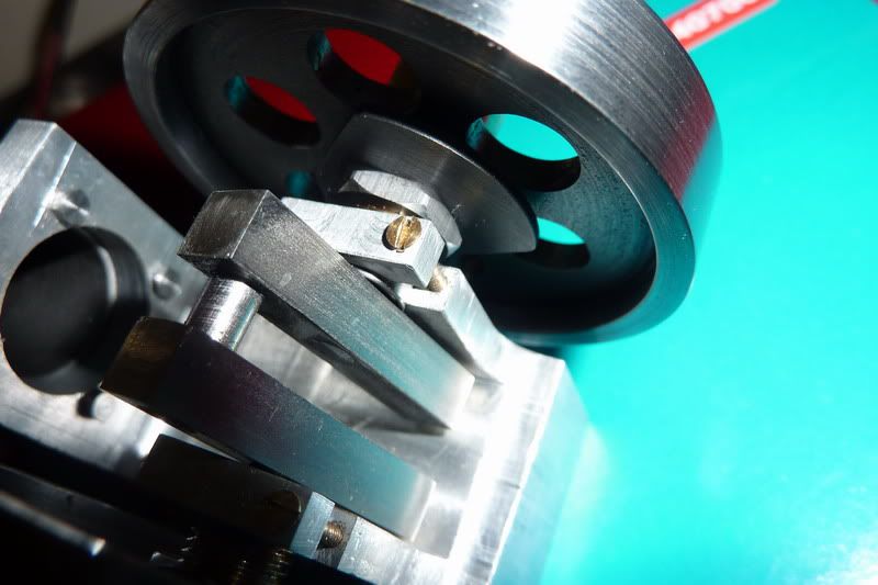
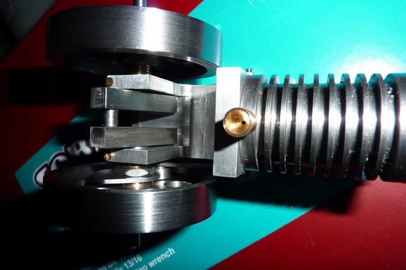
Getting nearer to the elusive finishing line!
Nick
Started making the valve rod. This was just a bit of 1/16" stainless rod with a thread on each end. The thread, unfortunately had to be 10ba (bit small for my liking). 1/16" is too small for my lathe chuck to grip so I had a cunning plan, or at least I thought I did... hold it in the pin chuck:
but this didn't really get a good enough grip. The collet was just too big so it slipped. So put the drill chuck in the headstock:
Worked this time. My new Soba 10ba die from the set I got for christmas didn't seem to be working very well though so used an old presto one and that worked!
Using 10ba also meant that I didn't have any nuts. I found one then had to drill another out that was even smaller!
Tapped in vice as couldn't feel what was happening in lathe:
The next thing to make was the valve rocker shaft. This was from 1/8" silver steel. First had to turn ends down for 8ba:
Then cut the threads:
Then had to think of a novel way to clamp in the vice level - this is the heath robinson way I came up with, rested on a parallel and used a bit of packing in the jaw to grip. Here I am centre drilling:
Seemed to work reasonably well, drilled out to tapping size and started tapping:
I was just thinking, this tapping lark in the milling machine is ok as long as use a low speed and oil and keep winding in and out... then ping!!!
I don't really know what I was thinking, 10ba in silver steel under power? Really?! I started it off with the taper ok so I should have taken it out at that point to finish by hand but no, I had counted my chickens so to speak!
Luckily I managed to punch the tap out with a bit I ground off the end of the tapping drill. I thought I had a pic but can't find it. I had actually drilled it a size smaller to attempt to get a tighter fit so that won't of helped, but it helped save it. It had only tapped a couple of threads so I opened it up to the proper size and tapped again, I hasten to add in the vice this time!
This was before de-burring:
Assembled with rod and nuts:
I then made the spring as was running out of time, that was nice and easy:
There's the assembly with the spring:
Forgot to mention that this was during the day on Saturday afternoon, I was allowed into the workshop for staying in the night before! The intention was to go back in later that night after watching a bit of silly sat night TV but I was too tired and only managed a bit. Did the valve shaft bushes.
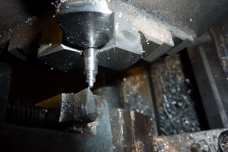
Drilling the rod. Think it's phosphur bronze but not sure, it came off a set of old scientific scales I think. It's sort of coppery and seems soft to turn? Anyway, it's the same stuff I used for my bushes on the ridders flame gulper.
Reaming 1/8" with my other christmas pressie:
Turning down to size. I wanted a light press fit, if too heavy it would crush due to thin wall and my 1/8" dia would be no more!
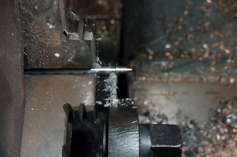
Finally parting off:
I thought the parting off was going badly as it kept leaving a pip (even though it was dead on centre) but luckily the pip just crumbled away and it was ok after a couple of twists by had with a countersink:
Then I tried the shaft in it and it was too tight! Then I remembered what Bogs told me about hand reamers having a longer tapered section, but I had reamed it blind so put it back in the lathe and reamed right through:
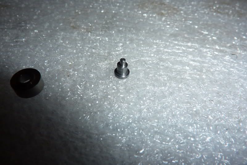
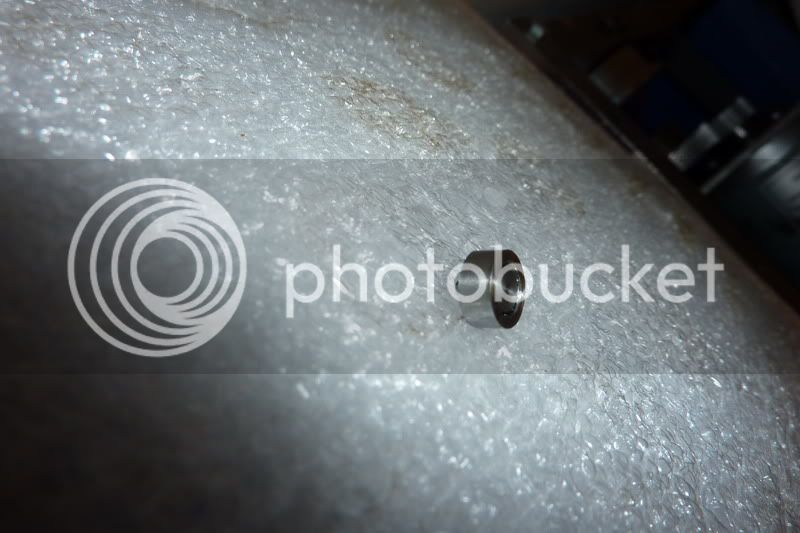
Another thing I noticed was that despite me being careful and using the graduated dial on top slide to make sure I parted off the right amount, it was coming out over size. I wasn't too concerned about this but when I started looking at the drawing, it was critical, the shoulder had to be 0.025" so that the shaft would protrude slightly at each end so I had to skim this down. Here is the finished bush:
Once I'd done the same for the other one, I'd had enough and quit while I was ahead. I just pressed the bushes in with a dab of loctite.
On Sunday I was allowed in the workshop during the day again ... what's going on? :scratch: !
So I set about making the cam(s). These are 1" diameter and 0.047" thick. I decided the best way would be to turn a bar to 1", drill, ream and part off. I had a little short length of cast iron I thought would be good as I know it's easy to part!
Facing off:
Turning to size:
Centre drilling:
opening up:
by the way, what do you leave on there to ream? Some people say make the reamer work, some people say just a smidgin ... I drilled 7.5mm for the 5/15" reamer I think and it seemed about right?
Reaming:
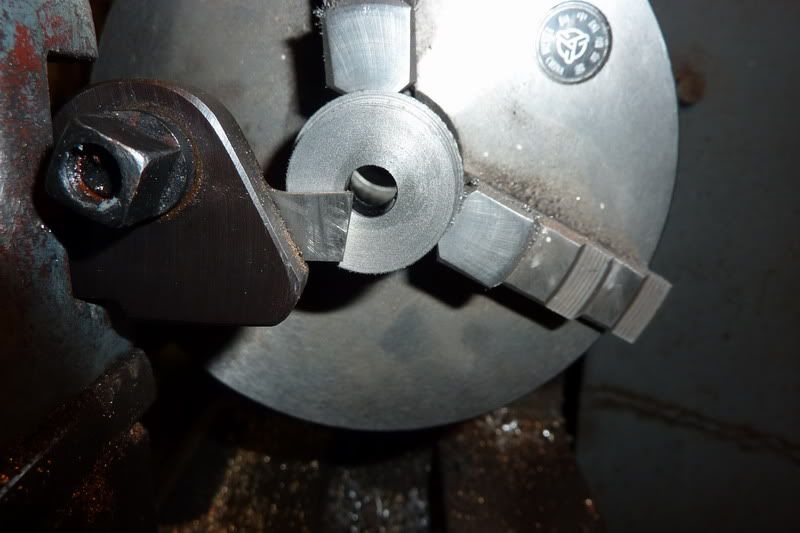
Then i set my parting tool up, looking from this angle I quickly realised you don't need to have much sticking out:
Parting off, used the centre as I wasn't gripping on much so remembered the advice from last time:
Here are the two blanks. One turned out 0.049" and the other 0.045" - oh well, think it'll do though!
The radii on the bottom of the cam was 0.300" so I set about making 2 filing buttons of 0.600" diameter with a 5/16" hole through the same. I took photos but just realised the entire operation was exactly the same as the cams, just from steel and a bit thicker! The only thing new was that it was the first time I've sucessfully parted steel :ddb:
I should have mentioned that I luckily remembered about the arbor I'd made for the flywheels which was the right diameter to hold it. With a bit of foresight, the od of this could have been made the same thereby incorporating filing buttons, but I had made mine from hex bar to index for the flywheel holes.
Here are the blanks mounted on the arbor with filing buttons and marked:
I thought, that looks wrong some how, and another look at the drawing confirmed that it was. The 110 degrees duration is shown in a funny way, so I interpreted what it meant and re-marked. You probably can't see it very well.
I thought I had a couple more photos but I can't find them. Anyway, I just hacksawed most of it away with junior hacksaw and filed the rest. The filing buttons didn't really work as they were just steel and not hardened but were there as a visual guide I suppose! I fear I may have taken a bit too much off so not sure whether the valve will be open long enough. Will see.
Sorry, it's a long post this ... need to update more frequently in future in bite sized chunks!
Next was the roller, pin and arm in that order.
The roller was from a bit of stainless steel:
Facing:
Turning to size:
Drilling:
I decided I'd have to grind a drill flat to square out the counter bore for the pin as didn't have a slot drill or end mill small enough:
Drilled with right sized drill first:
Then flat drill before parting off:
I tried to be clever when parting to give it the 1/64" step which sort of worked but I did my calcs wrong and it ended up too long anyway. Hadn't read drawing properly and added 1/64" to overall length. To that had to come off. Needed to ream it through anyway though:
Here are a couple of pics of the finished roller:
Parting the stainless was worse than the mild steel - tended to chatter a bit, prob had speed or feed wrong.
Onto the pin, simple turning job but had to be the right dimensions again.
Facing:
Turning bearing surface:
Turning pin:
Parting:
Finished:
Assembled into roller:
Now the arm, which would complete the whole valve assembly. I was going to use some 1/4" square bar, drill the holes and try to split it giving me 2 components but I decided that was destined to fail and I was making hard work of this. So I routed around and found some rusty steel sheet just the right thickness. Had a bit of straightening to do then cut a bit off.
Squared up in milling machine:
Here it is:
Marked it up:
Cut off and squared it up again:
Then had to re-mark it:
Drilled holes:
Then, by eye put at an angle in vice to mill angled sides. I didn't just do it willy nilly but thought I'd align the centre of the big hole and the bottom of little hole with the top of the vice jaw which would give the required offset.
After a bit of filing, it worked pretty well:
Then assembled the pin and roller onto it:
The idea was to peen over the pin, but without a ball pein hammer or rivet snap I had to use a nail punch, which worked well enough. I was really impressed with the roller, it spins over almost like a ball race but a bit looser. Probably due to the relatively hard metals it's made of.
That's about as far as I've got. Still on track, just the piston, rod & big end, burner and wooden base to complete. I've decided against the metal base (again!). I was going to make a brass one and machine turn it but I decided you can only see 3/16" all around so it's not worth it and it's pointless to boot!
Here are a few snaps of the assembled engine so far. What a fiddly job that was :lol: shame it's got to come back to bits! :doh:
Getting nearer to the elusive finishing line!
Nick
Thanks Kel,
Sorry that was a bit of a long post, I seemed to find myself taking pics of the same thing over and over just with different bits of metal in the chuck! I think in future I'll just take pics of anything significant that could either help others or if I need some advice. Any regular sort of basic machining I won't bother but will just take a pic of the finished component. It doesn't help with me waffling so much either!
Yep, you're right, just the piston, con rod & big end to get to the point of a finished engine. As I said, not bothering with the metal base but will need a wooden base. I thought that glass burner from my chemistry set when I was a teenager might work but it's the wrong shape - damn thing, I will find a project I can use that on one day! So I'll need to make a burner.
I'm only making 1-off of most parts at the moment as it was taking too long. If it works, I then need to make some parts for a gear linkage for a friend who's doing a honda vtec conversion on his Lotus Elise. Then I'll have a month break from the workshop and then I'll have a month to finish the other at slow pace before my dad's Birthday. I'd feel rather have the two engines working before giving one away - even if it is to my dad!!
Nick
NickG said:Thanks Kel,
Sorry that was a bit of a long post, I seemed to find myself taking pics of the same thing over and over just with different bits of metal in the chuck! I think in future I'll just take pics of anything significant that could either help others or if I need some advice.
Nick
Nick:
Looking good, and I 'm looking forward to more... I really haven't wrapped my head around how these work, so
you are teaching me as you go. As to posting pictures of set-ups, bear in mind that sometimes what seems entirely
basic to you will be an "A-ha!" moment for somebody else. There are many things I now do as a matter of course that
I would never have thought of had I not seen it elsewhere....
Just my 2 cents worth ;D
Joe
Joe, thanks for that and good point made.
I think some people get the wrong end of the stick as to how they work and the term vacuum engine doesn't help, really it should be atmospheric engine. I have been confused in the past too, but when thought about logically, the way I understand they work is (in a non scientific way!) as follows:
The piston travels down the bore towards bottom dead centre with the valve open and draws it very hot gas. That gas, at the high temperature occupies the swept volume of the engine, then just as it nears bottom dead centre the valve closes, so you now have a closed vessle with the gas at high temperature at the swept volume and atmospheric pressure. But the gas is rapidly cooling, so this lowers the pressure to below atmospheric pressure, hence there is a larger pressure on the other side of the piston pushing it back. At the same time however, now the piston is travelling back and the volume is decreasing so there is a point where the rate at which the gas is cooling is less than the rate at which the volume is decreasing, therefor the pressure starts to rise and gets to atmospheric - at this point there is no power left in the stroke (nothing pushing the piston back) so ideally the valve should now open, otherwise you're just losing momentum trying to compress the gas. Some engines incorporate a relief type exhaust valve to achieve this, in poppin's case, the valve is just held against the port face by its inherant springiness so once the pressure inside gets above atmospheric, it simply lifts the valve off its face - giving it the distinctive popping noise!
Well, that's the idea anyway, just hope mine will run!
Hope that helps.
Nick
I got a bit more done last night and today but the last few bits are taking a lot longer than I expected so slightly behind schedule. Going to cinema tonight so won't be making any further progress tonight!
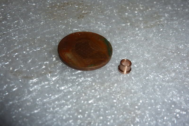
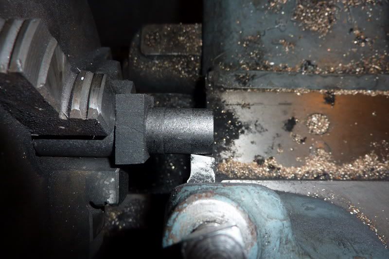
I started work on the piston with the graphite kindly donated by a member of another forum.
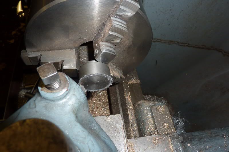
I sawed a chunk off and just gripped it in the 3 jaw - would have been better in the 4 jaw but as long as it held, the cutting forces are very low so I was able to turn myself a new datum to work from.
Faced the end:
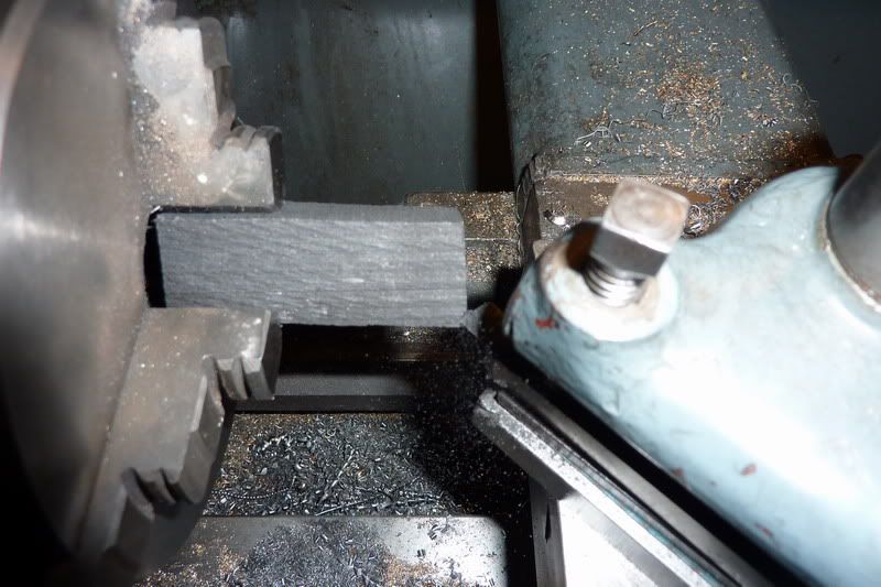
Then turned a length any old diameter to grip on:
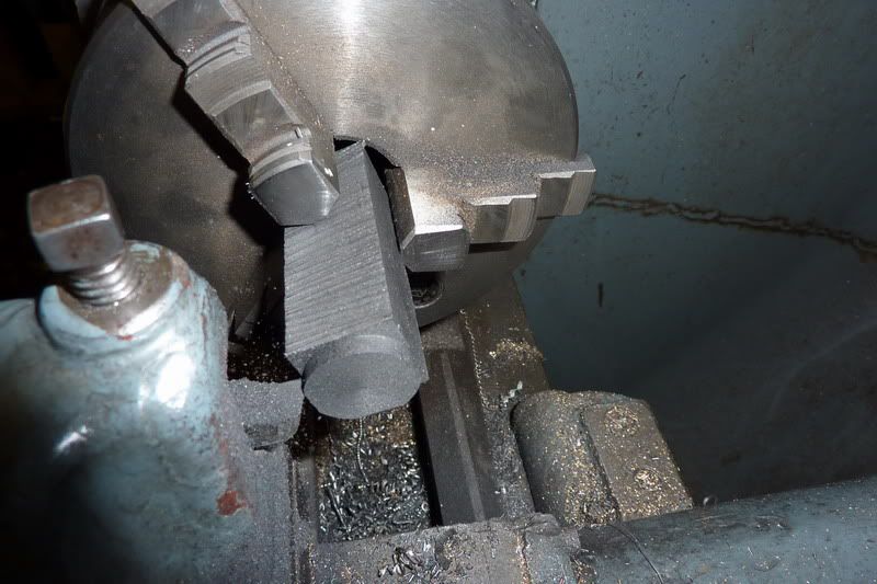
Flipped it around, faced:
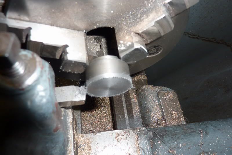
Then started turning down to size:
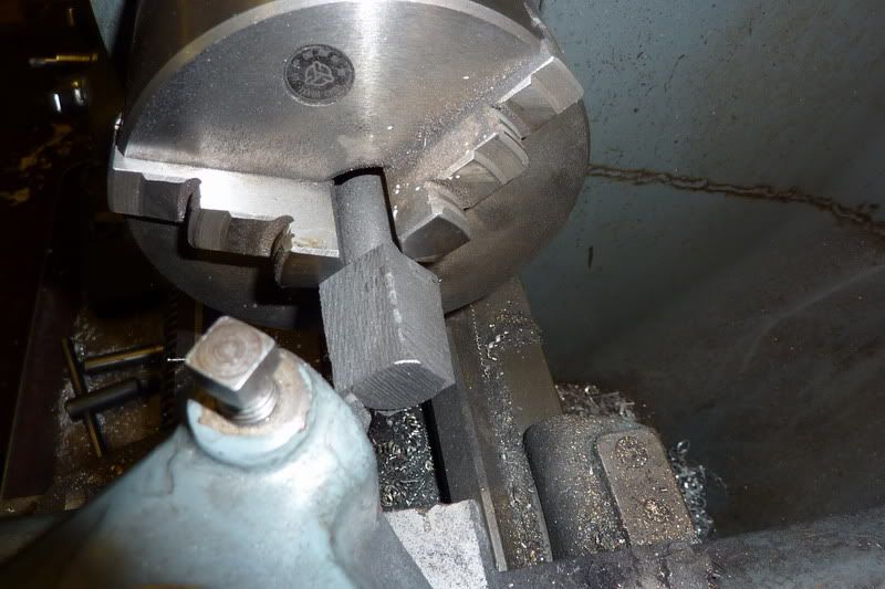
Now taking the tiniest finishing cuts, something like 1/4 of a thou but easy to do with this material:
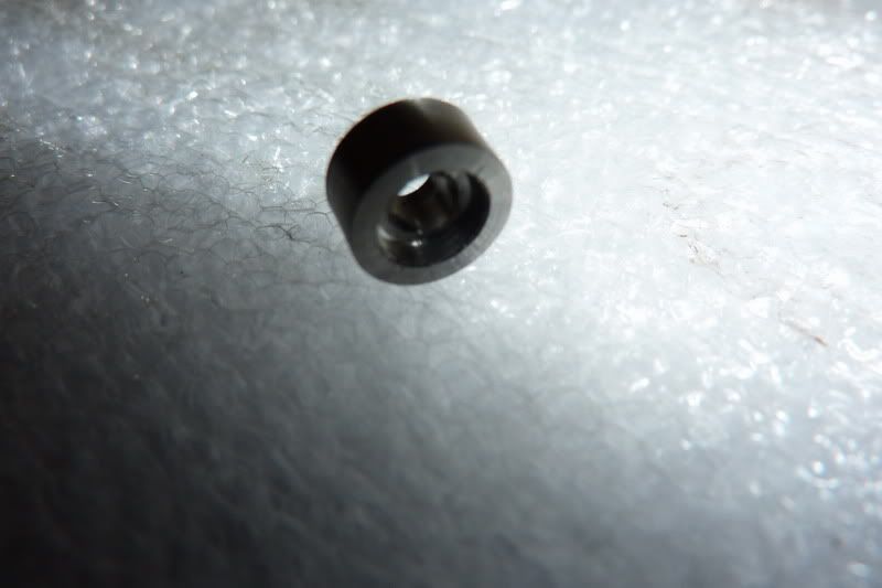
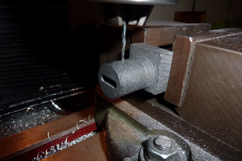
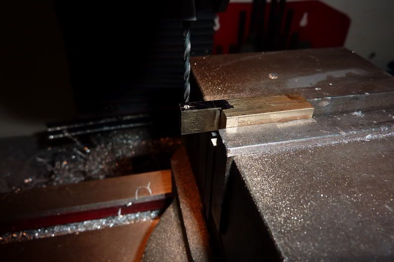
Across into the milling machine to mill the slot for the con-rod. When I was turning the datum, it dawned on me to stop short and it would give me something to rest on and keep square in the milling vice. I just cut to the full depth using a 1/8" end mill. I widened the slot slightly though by a few thou as I'm using 1/8" silver steel for the con rod.
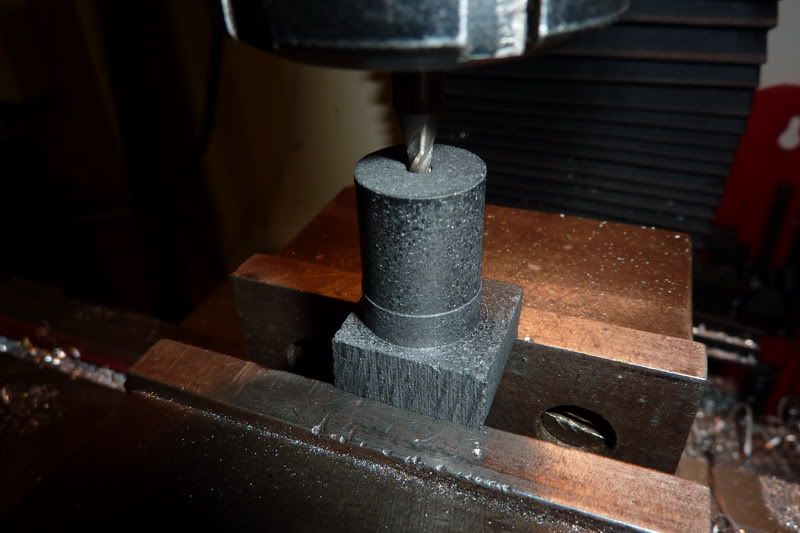
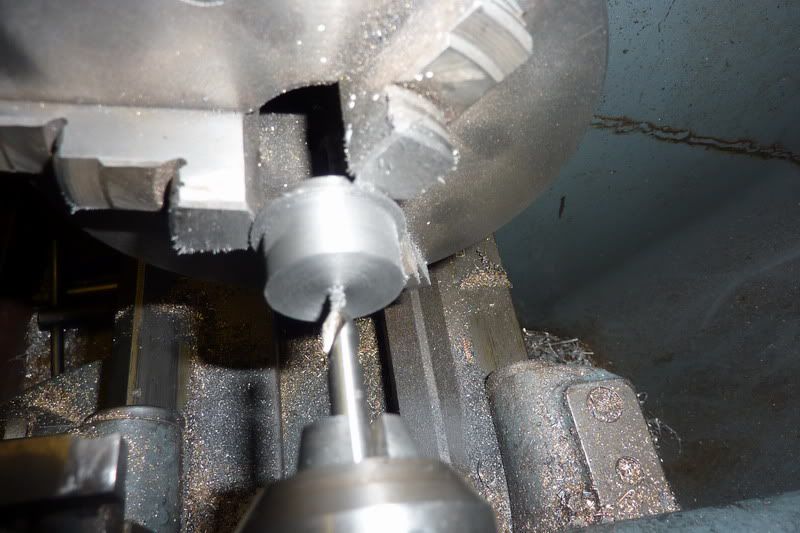
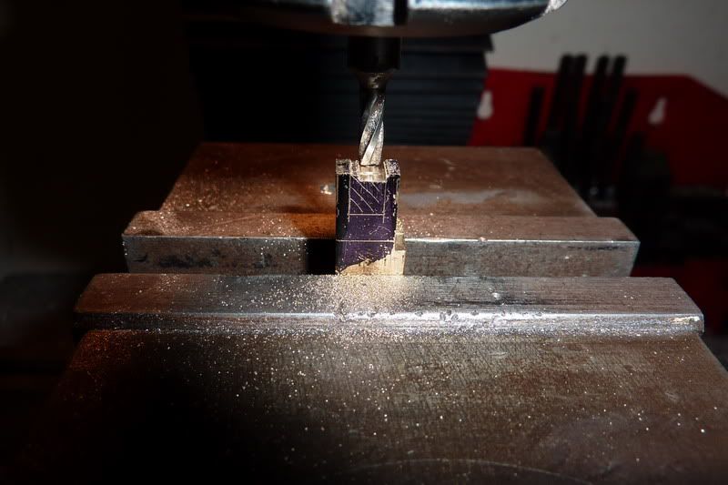
Flipped on its side to drill hole for gudgeon pin. I've drilled it for a push fit in there so it stays in place and the con rod will have the clearance hole. I wasn't sure whether the graphite would wear, probably not but anyway, that's what I've done.
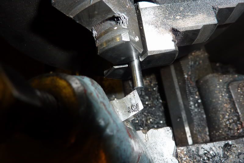
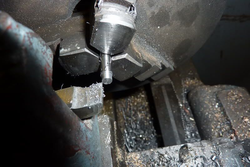
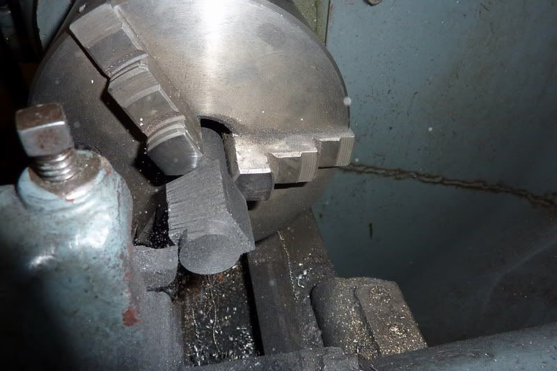
Back into the lathe to part off:
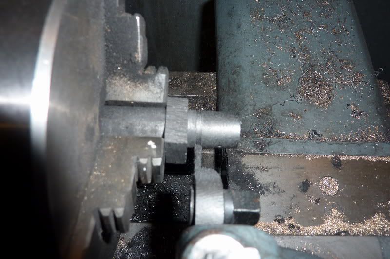
Because it's quite brittle it snapped with about a 3/16" pip so I had to put it back into the chuck to face off with some aluminium to protect it:
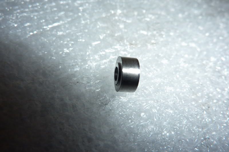
There's the finished piston with the gudgeon pin:
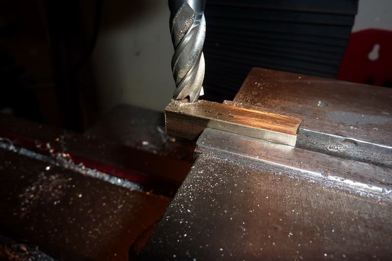
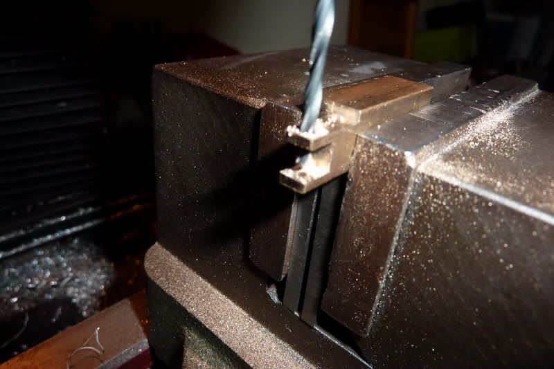
Next was the conrod big end. This is made up from a couple of bits of brass fastened together then drilled so it can split and be fastened to the crank. The problem was, I didn't have any 3/16" square brass, so I would have to turn some 3/8" down (smallest my 4 jaw can cope with) and then mill the square down to 3/16". This is what took much longer than it should have given the right material.
Facing the 3/8" brass:
Drilling for the 1/8" rod:
Turning down to size:
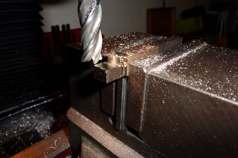
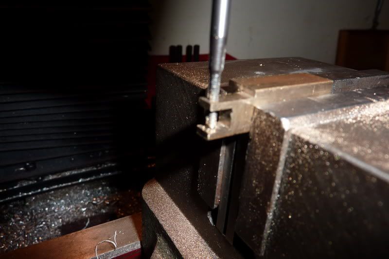
Over to the mill to whittle down to 3/16"
And the other side:
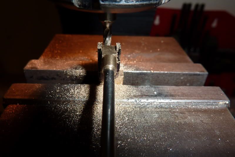
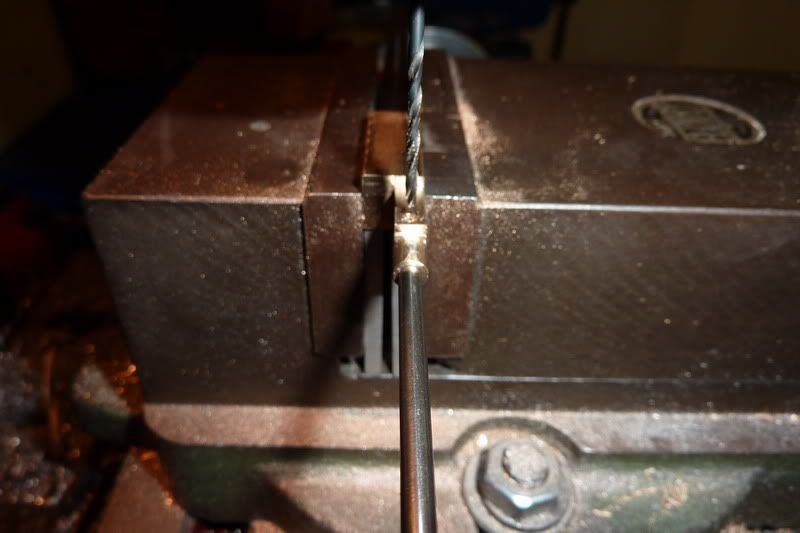
Centre drilling for pin:
and drilling through:
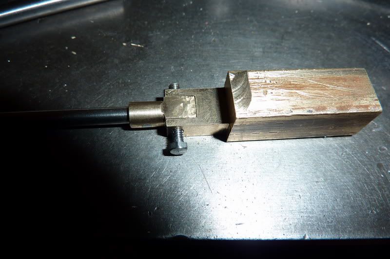
Sawing off the parent stock:
facing to length:
It was supposed to have a 1/16" rivet in it but as I said before, I didn't have a rivet snap so I just filed it off flush, made a bit of a mess but it's ok I guess:
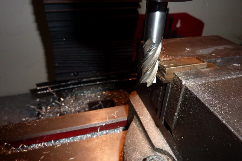
The other part of the big end has a slot milled into it and fits snugly over the last bit like a clasp (think that's the word!) So this is 3/16" wide to fit between the crank webs and 5/15" deep.
Squaring up the brass:
Milling down to 5/16":
and 3/16" in the other plane:
Squaring the other end so I can stand upright to mill the slot:
Marked up and ready to mill and drill:
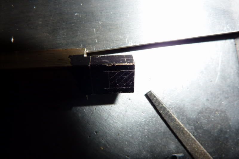
Drilling for the pinch bolt - notice my mistake here, I'd already centre drilled it.
Milling the slot - I nearly made a booboo here, I used the graduations on the handwheel to get the width - which didn't work but luckily I had a small cut on and I noticed soon enough. So I just went to my markings my eye then measured each side and the bit it slots over and took appropriate amounts off.
This is what I probably should have done before, don't know why I didn't drill it in one sitting. I had to re-position and pick up the original hole:
Opening up the top prong for 8ba clearance:
and tapping the bottom prong:
At this point I thought I'd finished, but I still need to drill the holes for the crank journal and gudgeon pin and cut the rod to length - just minor points!! I was worried before about getting those two holes parallel but of course because I haven't done either it will be easy, just do it at the same setting.
After that, the engine is technically complete, I just need a base and a burner - which begs the question, do I try it by lashing it together before I have made those, hold the camera with my teeth, burner in one hand and other hand to flip the flywheel! :lol:
Nick
I started work on the piston with the graphite kindly donated by a member of another forum.
I sawed a chunk off and just gripped it in the 3 jaw - would have been better in the 4 jaw but as long as it held, the cutting forces are very low so I was able to turn myself a new datum to work from.
Faced the end:
Then turned a length any old diameter to grip on:
Flipped it around, faced:
Then started turning down to size:
Now taking the tiniest finishing cuts, something like 1/4 of a thou but easy to do with this material:
Across into the milling machine to mill the slot for the con-rod. When I was turning the datum, it dawned on me to stop short and it would give me something to rest on and keep square in the milling vice. I just cut to the full depth using a 1/8" end mill. I widened the slot slightly though by a few thou as I'm using 1/8" silver steel for the con rod.
Flipped on its side to drill hole for gudgeon pin. I've drilled it for a push fit in there so it stays in place and the con rod will have the clearance hole. I wasn't sure whether the graphite would wear, probably not but anyway, that's what I've done.
Back into the lathe to part off:
Because it's quite brittle it snapped with about a 3/16" pip so I had to put it back into the chuck to face off with some aluminium to protect it:
There's the finished piston with the gudgeon pin:
Next was the conrod big end. This is made up from a couple of bits of brass fastened together then drilled so it can split and be fastened to the crank. The problem was, I didn't have any 3/16" square brass, so I would have to turn some 3/8" down (smallest my 4 jaw can cope with) and then mill the square down to 3/16". This is what took much longer than it should have given the right material.
Facing the 3/8" brass:
Drilling for the 1/8" rod:
Turning down to size:
Over to the mill to whittle down to 3/16"
And the other side:
Centre drilling for pin:
and drilling through:
Sawing off the parent stock:
facing to length:
It was supposed to have a 1/16" rivet in it but as I said before, I didn't have a rivet snap so I just filed it off flush, made a bit of a mess but it's ok I guess:
The other part of the big end has a slot milled into it and fits snugly over the last bit like a clasp (think that's the word!) So this is 3/16" wide to fit between the crank webs and 5/15" deep.
Squaring up the brass:
Milling down to 5/16":
and 3/16" in the other plane:
Squaring the other end so I can stand upright to mill the slot:
Marked up and ready to mill and drill:
Drilling for the pinch bolt - notice my mistake here, I'd already centre drilled it.
Milling the slot - I nearly made a booboo here, I used the graduations on the handwheel to get the width - which didn't work but luckily I had a small cut on and I noticed soon enough. So I just went to my markings my eye then measured each side and the bit it slots over and took appropriate amounts off.
This is what I probably should have done before, don't know why I didn't drill it in one sitting. I had to re-position and pick up the original hole:
Opening up the top prong for 8ba clearance:
and tapping the bottom prong:
At this point I thought I'd finished, but I still need to drill the holes for the crank journal and gudgeon pin and cut the rod to length - just minor points!! I was worried before about getting those two holes parallel but of course because I haven't done either it will be easy, just do it at the same setting.
After that, the engine is technically complete, I just need a base and a burner - which begs the question, do I try it by lashing it together before I have made those, hold the camera with my teeth, burner in one hand and other hand to flip the flywheel! :lol:
Nick
- Joined
- Jan 3, 2008
- Messages
- 2,085
- Reaction score
- 17
Wow Nick....that is a lot of progress, and it all looks so good too! Lots of fiddly little bits and pieces there at the end too. Can't wait to see this one running. Great pictures of the build throughout also!!
Bill
Bill
Thanks Bill, I thought when I started it looked good, but then seeing all the great stuff on here it's probably average at best! It is the most fiddly thing I've built without a doubt. Cheers Kel, it's not too far off now but I've dropped down to one of each part after the frame took its toll on my patience! I won't be doing anything tonight but hopefully by friday night I'll be ready to try it! Can't wait either - might get the camera set up the first time I try it so you can either hear the disappointment or elation in my voice!
Nick
Nick
Similar threads
- Replies
- 148
- Views
- 20K