'Poppin' Flame Licker Engine

Home Model Engine Machinist Forum

Help Support Home Model Engine Machinist Forum:

This site may earn a commission from merchant affiliate links, including eBay, Amazon, and others.

NickG

Well-Known Member
Joined
Jun 20, 2008
Messages
1,025
Reaction score
19
Hi all,

I've had a bit of a break from the workshop after the trials and tribulations of getting my Jan Ridders Internal Valve Flame Licker running. I decided towards the end of that project to make a 'Poppin' flame licker which is a more conventional design. I decided on that incase I was utterly disappointed and couldn't get the other one working, but now I intend to go through with it, mainly as I am intrigued to see how different they are to make and how differently their running characteristics are. It will also introduce some new machining / modelling techniques that I haven't used before. So I bought enough materials to do two when I had my pessemistic head on, basically so I could make anything twice to get it to work if need be! Now, the plan is to learn from previous experience and carefully make two of everything so I end up with 2 engines! I was going to try to keep this shorter and sweeter than my other build logs as I tend to ramble a bit and it takes twice as long to finish a project! Not sure whether I can do that though - lets find out!

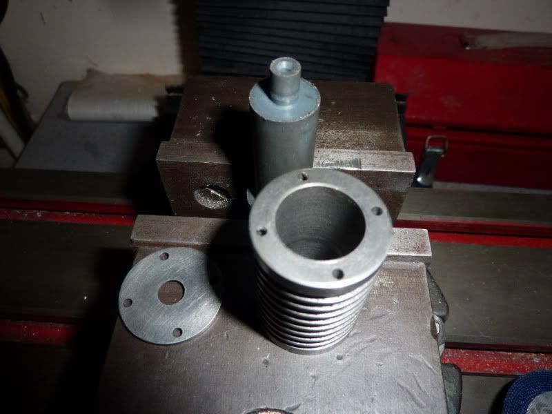
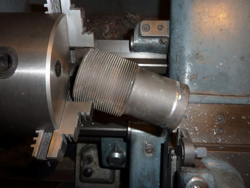
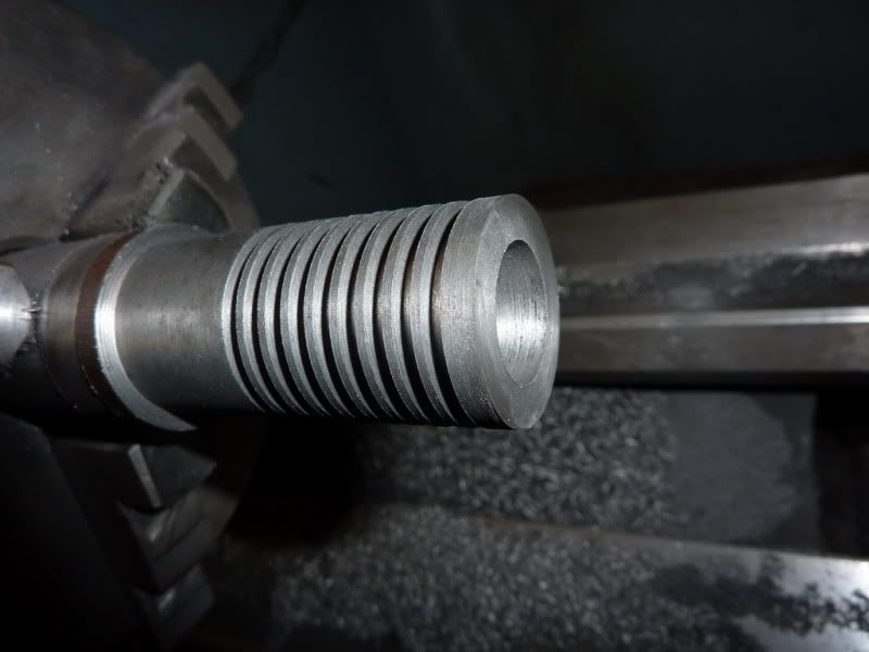
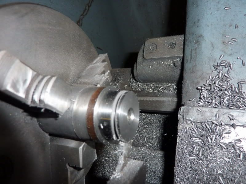
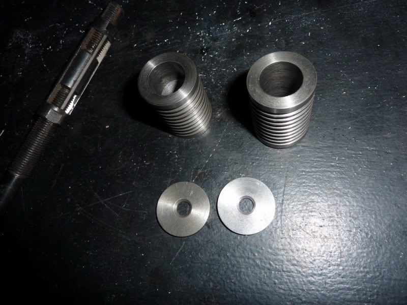
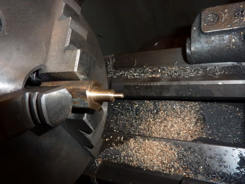
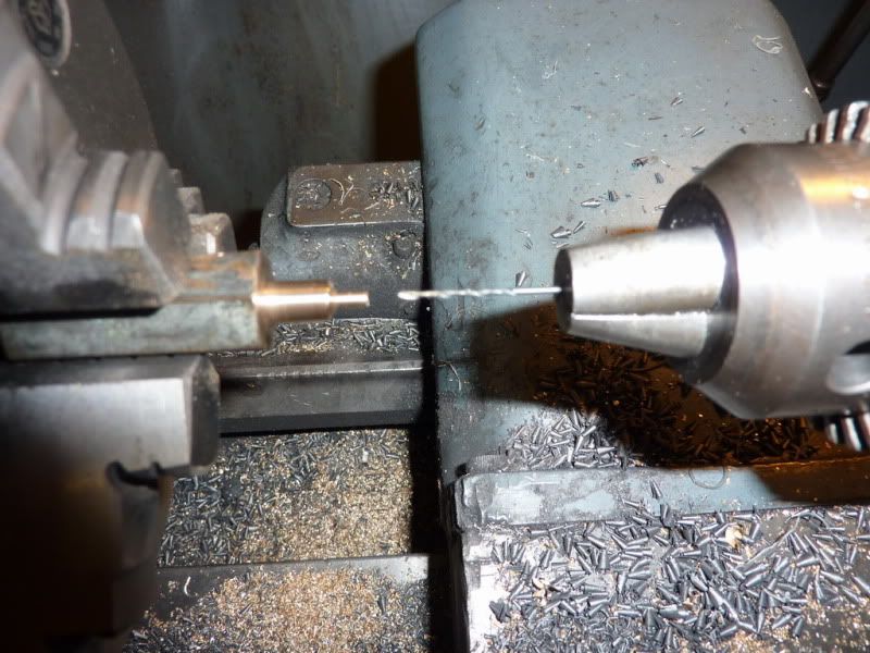
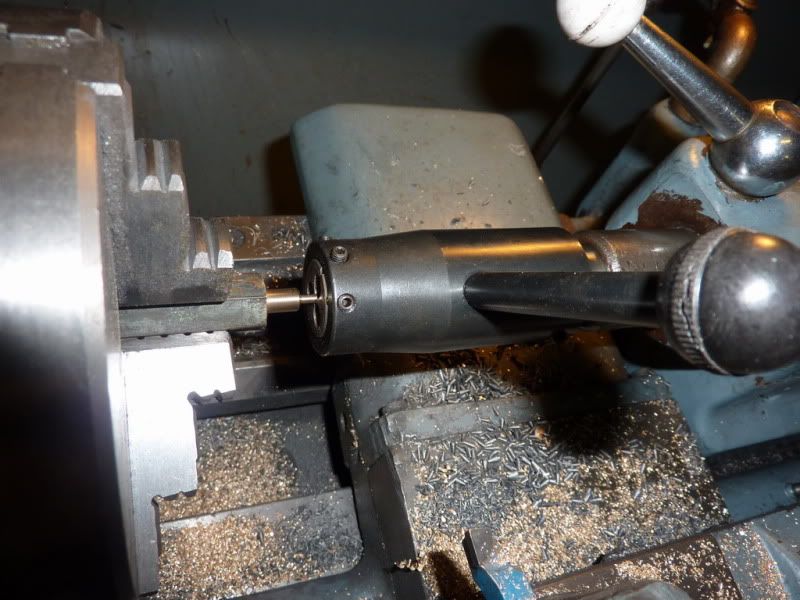
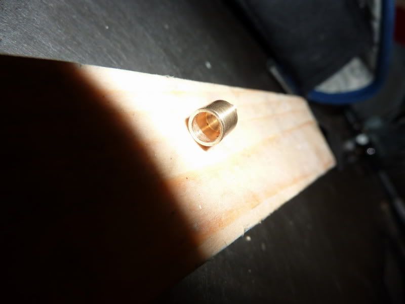
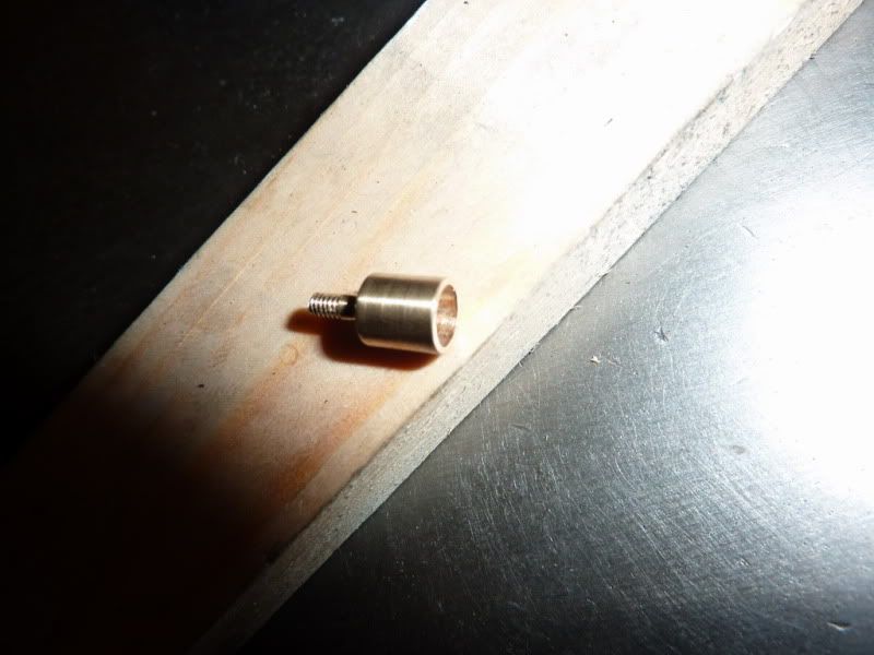
Last night I made a start with the cylinder - no pics at the moment but it's still in the lathe so I'll get a couple of snap shots tonight. If I get things right, it shouldn't take twice as long to make two engines as I should save a bit here and there on set up times. So I'm planning on completing these in a month - knowing me and my past predictions, that could easily stretch to two!

Nick
 
Nick,
I am in the exact same position you are in. I too just completed a Jan Ridders internel valve, and it was indeed a chalenge. (however with the help of this site, I was able to get a nice runner)

So, Yesterday I was looking on the net for another flame licker engine to build, I found vids on the poppin engine and wanted to build one. I wake up this morning and what do I see, this thread, almost like a mirror of my . So I found some plans, but they are difficult to read, the look like they came out of a magazine. The plans are good enough to complete the project, I think.

Where did you find your plans?

Kel

PS

the plans call for an oiler to be installed on the cylinder, and asbestos chord for piston rings. Can I scrap these Ideas and make it "wet lube" free, like the jan ridders design?

 
Kel,

Yes I saw your build log in the final stages, well done for getting a runner it was tricky but made it all the more satisfying!

Haha, what can I say, great minds think alike. It sounds like I have the same plans from live steam magazine. Mine are a poor copy too but can make out the sizes.

The plans I have do not have any piston rings but does have an oiler. Are you sure you have poppin plans or something else? I've mentioned before there are 2 schools of thought on oil, I'm in the 'with' school because that is what worked best for me.

Let me know of any progress, or are you going to do a build log too? That would be good.

Cheers,

Nick
 
Nick,
Your right, there is no asbestos rings. I must have been thinking about a different one. (I seen so many).
I do plan on making a build log for this engine. I am also going to change the plans a bit to suit the materials I have. Mainly the frame part, I will keep the dimensions the same but my method of bracketry may differ slightly. I am going to use steel for the cylinder, and leaded steel for the piston. (this is what worked for me with the internal valve engine) the rest will be aluminum and brass. I was also toying with the idea of making walnut flywheels with brass spokes. Although I do not know it this will have enough mass. (maybee a little lead inside the wood could help) I do love the look of walnut and brass. My last engine has a walnut and maple base with brass spikes holding it together. Turned out really nice.


Do you know of any good pictures of the cam, and valve rocker arm instalation? This is the only part I cant make out looking at the vids, and pictures.

kel
 
Made a bit more progress last night.

This was how far I had got with the cylinder. Simple really - face end, centre drill, support with revolving centre, turn to diameter, turn grooves with parting tool (I didn't grind a special tool to width, just recalculated the number of grooves and widths I could do with my tool), drill and bore out 5 thou undersize to leave for reaming with adjustable reamer.

2010-02-0221-11-44_0001.jpg


Next I needed to polish it a bit and part it off. Then I thought while I had the right diameter I would part off the two cylinder covers. I had already drilled 1/4" through to that part of the bar before hand so all I had to do was countersink each one first then part off:
2010-02-0221-47-03_0002.jpg


I then got the 2nd cylinder to the same stage as the first so this is where I am up to:
2010-02-0223-29-40_0003.jpg


I still need to face the cylinders, ream for a nice finish in the bore and drill and tap holes on each end and for oil cup. For the cylinder covers I need to drill clearance holes for screws that fasten them on and lap both sides, one to seal with the valve nicely and the other with the end of the cylinder.

So far so good but don't think I'll make any progress tonight, Leeds vs Tottenham game is on (4th round FA cup replay)!

Nick

 
Lookin good Nick. you got a good head start on me.

kel
 
Nick, making two at a time is a good idea. If it turns out that they both make it to the end, you could make a twin cylinder engine out of them.

I noticed you used an expansion reamer to get to the final bore size. The finish looks pretty good. I have never have much luck with that type of reamer. What is your secret.
 
True Arv, the twin cylinder thing occured to me as I was writing the last post! But then I'd need a different frame and crank, still, could be done but the current thinking is to make 2 poppins and sell one to recover the material costs of my last few projects!

Nick
 
Hi all,

I 've been struck down with Man Flu :lol: I musn't have had a bad cold for about 2 years so forgot how bad it was! Anyway, still made a small amount of progress -

First I put the cylinders back in the 3 jaw with some protective thin aluminium around them and faced to length before using the adjusable reamer, I had adjusted it just about spot on, made it slightly larger than I had measured it and reamed right through at about 45rpm with cutting oil - this has produced a good smooth finish and very parallel and accurately sized bores - they have actually come out at 0.625" as intended, am quite astonished!

I then made a bit of a jig from nylon which had a 5/8" spigot and a smaller 1/4" one to hold the cylinder covers concentric. Gripped that in the milling vice and let the cylinder rest against the top of the vice jaws - probably not the best practice but I marked a cross on the cylinder covers with a centre square and a set square by eye. I then found the centre of my spigot in the milling machine and wound it out to the 0.422" or whatever radius it was then put a dab of loctite on the cyl covers to hold them on whilst spotting through with a centre drill, turning it around and drilling on each of the 4 scribed lines. This has produced a decent and repeatable result, I think the 2 covers will both fit on any of the 4 cylinder ends so I may have got lucky. If not, it wouldn't have mattered, they would have just been matched. I nearly messed up drilling the bolt holes on the other end of the cylinder - they have to be in the same place at both ends which only just occured to me before drilling. This is because there has to be a gap at the bottom for the valve to pass through! I opened the holes up to 8ba tapping size on the normal drill since

I didn't take any pictures of the jig yet but it's still in the milling machine as i still need to tap the holes so will get some pics tonight. I lapped both sides of each cylinder cover too.

I was a little bored of the cylinders by this time so on Fri night I decided to do something else – thought I’d try the oil cups. When I looked at the drawings the small numbers scared me but I thought they have to be done sometime so I’ll try and stick to it.

So chucked some brass hex in the 3 jaw and turned the outer body dia and smaller neck dia that’s threaded to go into the cylinder. This brass was rock hard – much harder to turn than stainless, I should maybe have used that.
2010-02-0521-33-21_0001.jpg


I then had to drill a 0.020” hole – no way I was trying that so I used my smallest number drill instead, no. 60 0.040” ! Twice the size but still the smallest hole I’ve drilled and small enough in my opinion! So the hole was drilled at the lathes max speed 720rpm, it coped surprisingly well, I had to drill about ¼” or so deep so just took it steady and didn’t break the drill to my surprise.
2010-02-0521-43-53_0004.jpg


I then cut the 8ba thread using one of my xmas pressies:
2010-02-0521-48-04_0002.jpg


Sawed it off, turned around in the chuck, drilled out with number 13 or something which broke into the tiny hole, then faced to length.
2010-02-0522-03-23_0003.jpg

2010-02-0522-05-27_0005.jpg


Quite happy with the result but I then had to repeat the whole process for the other one which is starting to bore me having to do everything twice but I’ve got to remember I’ll have 2 engines then!

Next job is to tap all the holes in the cylinders and do the pistons and yokes before I start on the frames.

Nick
 
Getting on well there Nick.

Now you have the experience of your first one, these should go a lot smoother, as you already now know a lot of the pitfalls with this type of engine.

If I could make a little suggestion to your machining regime.

When doing something like your oil cups, it is always preferable, if possible, to drill the holes after you have cut the thread. Putting the hole in first will weaken the metal substantially, the metal is a lot stronger without the hole when doing the screwcutting, and it isn't then liable to shear off.


John
 
Nick,
I sympathise with the "I'm getting bored of multiple parts" thing. A while back I started the "Miser" low temp stirling from Jerry Howell. Unfortunately, I decided that since it was the setup that takes the time, I would make six. What I forgot was all the hand work involved in finishing and "tweaking" that is not done by the machine but with my hands. I did change some of the cosmetics between the same parts, but, nevertheless it DOES get boring, no pun intended :)
I'm working on the colums now, I haven't gotton the first one done yet and I'm already tired of it...

The best of luck on your Poppin'.
MikeR C
 
Looking good Nick! What are you using for a flywheel, and how are you going to turn it?

Vic.
 
Nick,
I cant wait to see your method of drilling the holes. (pictures of it that is)
I used a rotary table for the round bits, and scratched my head on the standard. I found the easiest way was a simple x-y from the center. This made the holes directly on the top and bottom and thre sides. I am lucky I thought to turn the cylinder 45 degrees or the screw heads would be in the way of the valve.

Another flywheel question.
How big are you making th flywheel?

kel
 
John,

Thanks for pointing that out. I remember thinking after I had drilled the hole, why didn't I put the thread on first. I have found out to my cost in the past, I can't remember which part of the last project it was, but I sheared something off by not doing what you just mentioned. Oh yeah, it wasn't on the flame gulper it was the barb on the rocking engine. Good point.

Mike, I can't believe you are doing 6 of them! In future I'll just be doing 1 I think, depends how much I can get for the poppin - it might get a tidy sum, there are always people wanting such engines as they are a bit different to the usual steam or compressed air engines and they can be run just with some meths which is attractive. I guess that makes LTD Engines a more attractive proposition.

Vic, if I have enough, I will machine the flywheels from solid brass as per the drawings, but I don't think I do have enough so one of them will end up with steel flywheels to the same drawing - probably the one I keep as I always paint the middle red for some reason! The flywheel itself is a fairly simple turning job as the boss is separate so just a normal tool required to get into the corners.

Kel,

Unfortunately I don't have a rotary table otherwise i would have done the same. I will just use one the appropriate cylinder cover as a drilling jig for the standard I could probably use the same jig to concentre it with the hole and 'glue' in place while I spot the holes through. That's the plan anyway.

Current plans for the flywheels are as per the drawing. I usually try to cut back and make parts easier etc. One obvious way of doing that is to just have 1 flywheel per engine but to get the same moment of inertia it'd bea big flywheel unless you either double the thickness or have some 2.5" dia tungsten handy!

How are you going to tackle it?

Nick
 
Nick,
I am using 2 1/2 inch steel. I left the rim big enough so I could turn it down if necessary.

Kel
 
Nick, forgot to mention in my earlier post. Thanks for taking the time to document with so many good pictures, it really makes a difference to us newbies - I'm collecting material to make a Jan Ridders internal valve the same as the one you made some time back!

Vic.
 
No worries Vic, thanks for the interest. Good on you, i hoped my build on the internal valve engine didn't put people off but more provide some lessons to be learnt from my mistakes / findings! Good luck with your build, they are very satisfying engines to build and run.

Nick
 
Quick update, not a great deal of progress but worth mentioning.

I started by taking a couple of snaps of the simple jig I made to drill the holes as promised. It's not really the best jig, all it does is fix the radius and concenter the cover and cylinder. The rest had to be done by eye on markings on the cylinder cover just by gluing the cover on and rotating the cylinder. Seems to have been effective though and worked well.

2010-02-0921-33-20_0002.jpg


2010-02-0921-32-48_0001.jpg


I then wondered which part to make next and pontificated on a number of methods. I had some brass large enough and enough to do 2 flywheels, also had a bit of steel to do another 2. Then I found some brass 1/2" plate which I could have used. Or, some 2" steel which would make them 1/8" under size.

Anyway, whilst on the netti, I came to the decision to use the 2" steel as I would have little or no OD turning do do if I could drill centrally, just a bit of a polish up. I decided I wouldn't pussy foot about and would try to part off the blanks from the stock. So I went out full of enthusiasm, set the parting tool to the minimum overhang that would do the job, selected a suitable speed - very slow, back gear engaged, about 70 odd rpm, slowest cross feed to keep it nice and constant and even got ready with some suds in a syringe.

Then disaster almost struck - before I could react, this happened:

2010-02-0922-01-16_0003.jpg


I’ve moved the saddle a bit in that photo, the blade dug in shattered, and sounded like it hit all 4 walls, floor and ceiling but luckily missed me.
This was my thought process immediately after switching power off:

1. Oh ****, ******* ********.
2. I’m ok.
3. That could have been worse.
4. Actually I might have mangled the chuck and caused damage to the machine.
5. I think I might give up this hobby.
6. Take a step back and calm down a bit.

Seriously, it scared me. I’ve never parted off anything that’s steel as the feeling I get and noise have always put me off. This time I went for it as I thought I was being soft in the past, I thought I was doing it correctly but obviously not.
When I did calm down there seemed a tight spot on the chuck jaws, something has probably got bent. I took the jaws out, cleaned and reinstalled and it works, but there is a slight tight spot at some point so I must have done some sort of damage. It still grips and seems concentric though so hopefully I’ve got away with it.
Here is the damage to the metal:
2010-02-0922-06-13_0005.jpg

2010-02-0922-07-13_0006.jpg


There are a few major safety points that should go without saying:

1. Always wear eye protection – make sure you have eye protection you can see out of and are comfortable wearing and make sure you always wear it. I could easily be lying in a hospital bed wondering if I’d ever see again rather than writing this.
2. If in doubt, stop, I had a doubt in my mind I would be able to part this off but was trying to save time. I should have reached for the hacksaw at that point.
3. If you have a chuck guard you should probably use it. That piece of steel very nearly came out of the chuck – at the speed it was rotating it wouldn’t have been flung and I’m not saying the guard would have stopped it but it could only have helped matters. I’ll be using mine more in future that’s for sure.

I didn’t think there’d be an issue with me gripping on the threads of that bar, but with hindsight it may have been part of the problem. They were probably the weak point, deforming and allowing the stock to move. I did consider turning a parallel section to grip on but then I thought, it’ll grip tight on the threads and they will probably let the chuck jaws dig in a bit and get better grip.

So, I’ve calmed down a bit and the following hour and a half was spend with the hacksaw for punishment – aching now!:
2010-02-0923-30-33_0004.jpg


I did face the stock between each hack saw cut so at least 1 side of each blank is faced. Got a nice finish using the suds too, very good.

I could have not mentioned this mishap but I think it’s worth sharing these near misses just to give people a prod and make them think about things twice.

Nick
 
Two main reasons it happened Nick.

The first is that you should have machined those fins off first, they were definitely the weak point that collapsed when you put pressure on. And the second is that you were way too far away from the chuck with the cutting tool.

You were very lucky this time, but admitting to your mistakes and showing them is the right way to go, everyone learns.

I suppose you are out tomorrow, to buy a new pair of brown trousers. ;D

John
 
Just a tip if you part off that far from the cluck you can get away with it with a tail stock center in place until you are very close to the end of the cut. I've been where you were as I'm sure most of us have been before and it does get your attention in a hurry.
 
Back
Top