Parksy's v4

Home Model Engine Machinist Forum

Help Support Home Model Engine Machinist Forum:

This site may earn a commission from merchant affiliate links, including eBay, Amazon, and others.
Pipes look good. What did you use to bend them and are they the cheap SS drinking straws off eBay? (I'm hoping so cos I've got a heap of them in stock for the same purpose - just hoping they work).
 
Cheers Al.

I purchased the stainless tubes from Hong Kong off ebay. It's 8mm Diameter with 1mm wall and bends nicely. I just used a cheap pipe bender off eBay.
I also have some of those stainless drinking draws but I haven't tried doing anything with them.

Do a search for "capillary stainless tube" on eBay, this is the stuff I used.
 
The engine is really beginning to take shape Parksy. The exhaust pipes came out nice.
gbritnell
 
Parksy,

The blackening on the pipes can usually be removed with a rotary wire brush, I use my large buffing centre with a 5" wheel, but the small Dremel type might work. Try brass first then if that is too slow, revert to steel. If you use steel and it still isn't coming off, then it is most probably too embedded in the surface of the pipe. Then I think the only way is to polish through it as I don't think anything chemical will achieve what you need.
If the brushes work, you might have to repolish afterwards as there might be fine scratched left on the job.

John
 
Thanks guys, I'll use both the home made Pickeling paste and wire brush.

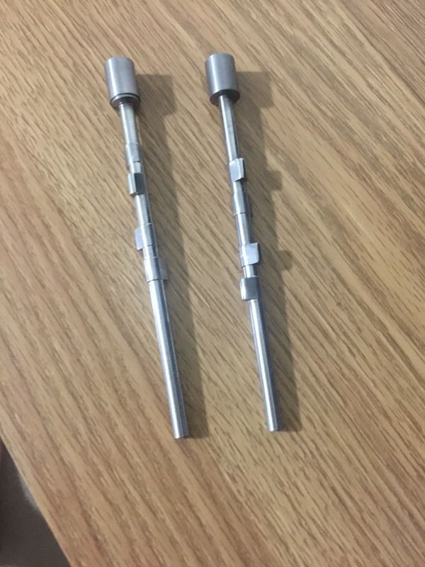
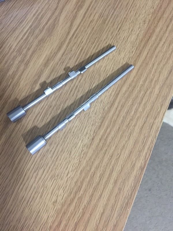
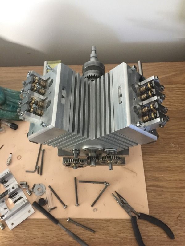
I milled the cam lobes this arvo. It's been something that's been worrying me but after doing it and being able to see it visually, I had realised that my initial angles were wrong and quickly rectified before I made any permanent mistakes. I'm happy with how they turned out, I just need to cut the ends off and sort the gear end.


Edit: if anyone is looking at the lobes and wondering what's going on, the two inside lobes on each cams are the intake lobes. Outer lobes are exhaust.
 
Parksy,
I may be in the midst of a senior moment, but don't your two cams need to be machined as mirror images to one another since they rotate in opposite directions? - Terry
 
Parksy,
I may be in the midst of a senior moment, but don't your two cams need to be machined as mirror images to one another since they rotate in opposite directions? - Terry

The cams will both run in the same direction. But maybe I'm also having a moment myself, so I'm happy to be corrected... please do so if I've made an error.

What happens on the left bank also occurs on the right bank (at a different interval ofcourse).
 
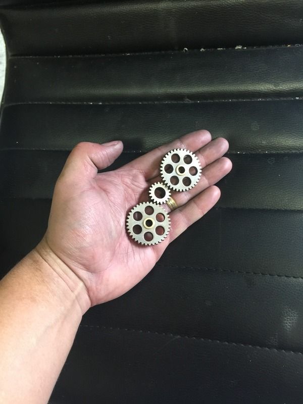
The cam gears I originally purchased from China, then dressed them up to how I wanted them to look. Unfortunately, despite being advertised with a 6mm bore, this was more like 6.5mm and would wobble a lot on the shaft. So I chucked the gear on the lathe and ran an 8mm end mill down the guts and made a bush for it to sit on. No more wobble.
I also nickel plated them for corrosion protection.

For the majority of the build, I had concerns with clearance inside the block. The cam lobes and con rods do touch as certain positions, and by touch I mean they lock the engine up. So I timed the cams to the crankshaft, gave it a spun and all is good! No contact! I discovered this issue when making the cam blanks and wondered why I couldn't install them into the block. So I was hoping that when I finally machined the lobes,(ie removed material from the cams) that this would eleviate this problem. Feeling relieved! Fluked it!


Currently working on some rocker supports on the head.
 
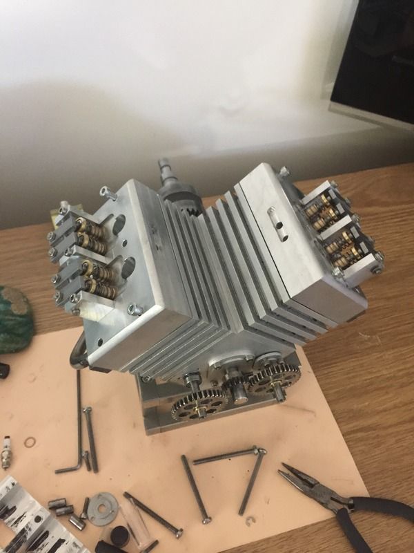
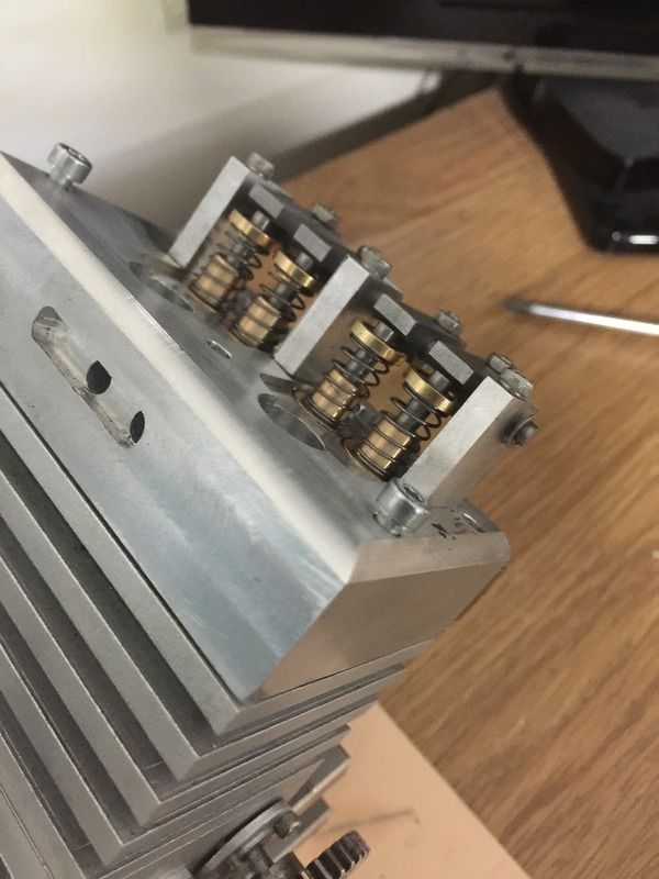
I've made a start on the rocker gear. Next will be the rockers. I've only ever used mild steel bar to make the rockers. I'll case harden the contact point and probably the rocker pivot bore also. Does anyone have anything against the use of this material in this application?
 
I made the lifters recently but out of an unknown material. I soon found out that it was stainless. So these were scrapped. I made another set out of drill rod and oil quenched them. They are file hard and slide nicely against the cam lobes.

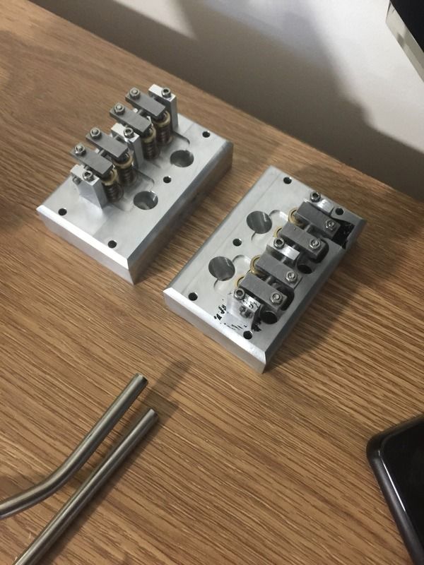
I've almost completed the rocker arms also. I used the angle grinder and cut individual strips and machined them individually. Time consuming but they are 90% complete. I will case harden them and nickel plate them for corrosion protection and to look nice.


Nickel plated the rockers. They came out really nice. And easy to do at home with only basic equipment.

 
Made spacers to locate the rockers to their respective positions.


I'm really pleased with how this engine is turning out, but I'm not sure what I want to do with the carby setup, whether I should have a single one in the middle or two seperate carbs. Open to suggestions.
 
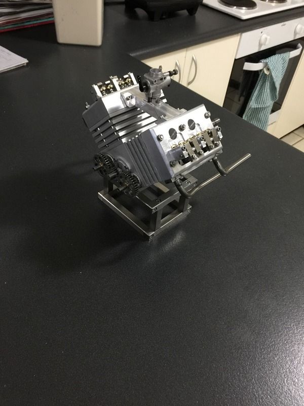
Decided to go the single carb for simplicity. I've made the intake manifold and mounted an RC aircraft carby on top. I've also replaced the head attaching hardware with studs.
Im starting to feel nervous about this build now. It won't be far from attempting a start, last major components are piston rings, pushrods, flywheel and the ignition components. That feeling of whether it will start or not is unsettling, but we shall see...
 
Parksy, looks great, Looking to start an engine, but have to order all the materials to start with, I have a supply of alloy plate and brass/bronze bush material but not the alloy blocks or steel bar stock.

Cheers
 
Cheers Ghosty,

Most of the materials I use I purchase online. There are some good sellers on eBay for aluminium bar where you can choose what size you like.

I am fortunate with where I am as there is a steel supplier, but only stainless and mild steel.

I regularly buy from this seller as they sell fine grain cast iron, bronze, 4140, etc
http://www.ebay.com.au/usr/offcuts.galore?_trksid=p2060353.m2749.l2754
 

Latest posts

Back
Top