I've seen a variety of opinions on "running in" cast iron rings, from "no run in at all" to "run in for 4 to 6 hours". I'm not qualified to speak from personal experience, because I have never been that successful at making and running cast iron rings on my model engines. However, to support Cogsy's opinion, I was involved in building many automotive engines for both street and drag cars, and none of those engines were "run in". Many of the "drag car" engines didn't even have the courtesy of being "worn in gradually" with the engine running.---and they all worked well to hold compression---and the compression did improve after the engines had ran for a while.
You are using an out of date browser. It may not display this or other websites correctly.
You should upgrade or use an alternative browser.
You should upgrade or use an alternative browser.
Parksy's v4
- Thread starter Parksy
- Start date

Help Support Home Model Engine Machinist Forum:
This site may earn a commission from merchant affiliate
links, including eBay, Amazon, and others.
- Joined
- Dec 9, 2015
- Messages
- 327
- Reaction score
- 349
Thanks for the advice guys. When I think back to when I got my last engine going, there was a noticeable difference in compression after running the engine (on petrol) a couple of times. But in saying this, I did initially run it on the lathe and this did give a little extra bounce. I don't really have an expert opinion on this as I'm still learning, but this time round I might try and give minimal running with the rings installed until I'm ready to fuel it.
Cheers
Cheers
I run almost all of my engines in for half an hour before firing them, but not for the rings. (I use Viton rings, which don't require any run in as they are a high temperature elastomeric compound.) Most times, due to build up of tolerances, the crankshaft or camshaft will "bind" a bit in the bushings. A good coating of oil and a half hour run in will get rid of minor binding and let the crankshaft spin freely. On my most recent engine build, the Rupnow Vertical engine, the crankshaft bearings were ball bearings, so didn't require any "run in", however I had minor binding between the crankshaft and camshaft gears, so the "run in" was more to free the gears up from any minor interference.
- Joined
- Dec 9, 2015
- Messages
- 327
- Reaction score
- 349
I gave the rotating assembly another run on the lathe and it spins a lot better now. I used generic additive free oil and dripped it onto the rotating parts to keep it lubed. One thing I've wondered is the oil turns black. I'm assuming this is minute amounts of metal particles. If things are bed in perfectly, does the oil stop turning black? Or at least to a lesser extent?
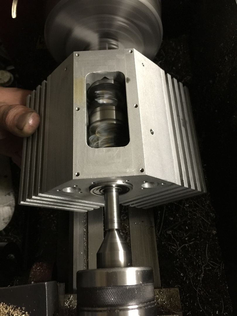

I think the right answer is "To a lesser extent".
- Joined
- Dec 9, 2015
- Messages
- 327
- Reaction score
- 349
- Joined
- Dec 9, 2015
- Messages
- 327
- Reaction score
- 349
More work done on the heads today. I miss read my drawings and accidentally drilled the valve holes in the wrong spot. Fortunately, because of the size of the cylinders, they still fit and I can use this setup. I have more room now for the spark plug.
Got a bit of chatter on the mini mill when cutting out the combustion chambers in the head, but the second attempt achieved a better finish by slowing the mill to almost a crawl.
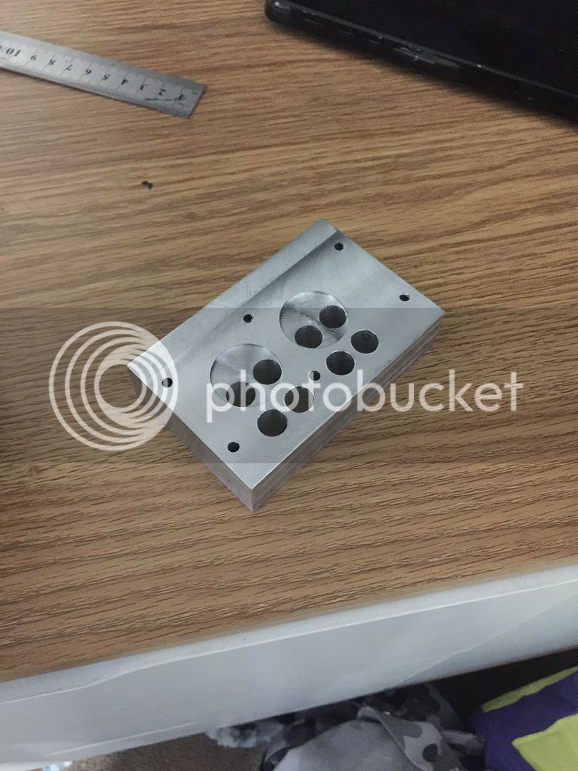
Got a bit of chatter on the mini mill when cutting out the combustion chambers in the head, but the second attempt achieved a better finish by slowing the mill to almost a crawl.

- Joined
- Dec 9, 2015
- Messages
- 327
- Reaction score
- 349
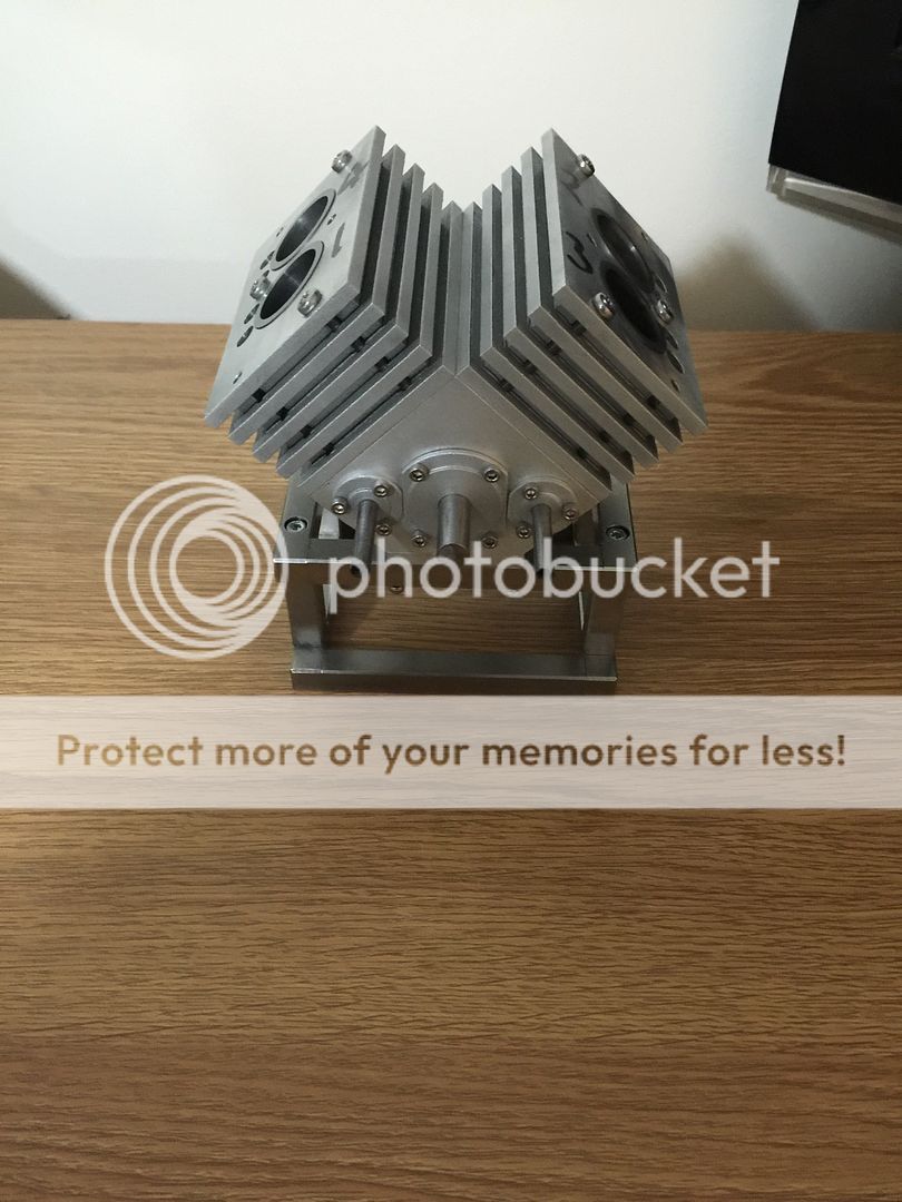
Making an engine on the fly without designs isn't that difficult a task, but making it aesthetically pleasing is difficult. Doing more work on the heads and trying to visualise how it is going to look once finished. Certainly takes a lot of thinking.
Thinking of using a ball nose mill and adding some shallow cooling grooves.
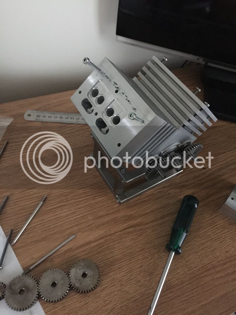
Thinking of using a ball nose mill and adding some shallow cooling grooves.

- Joined
- Dec 9, 2015
- Messages
- 327
- Reaction score
- 349
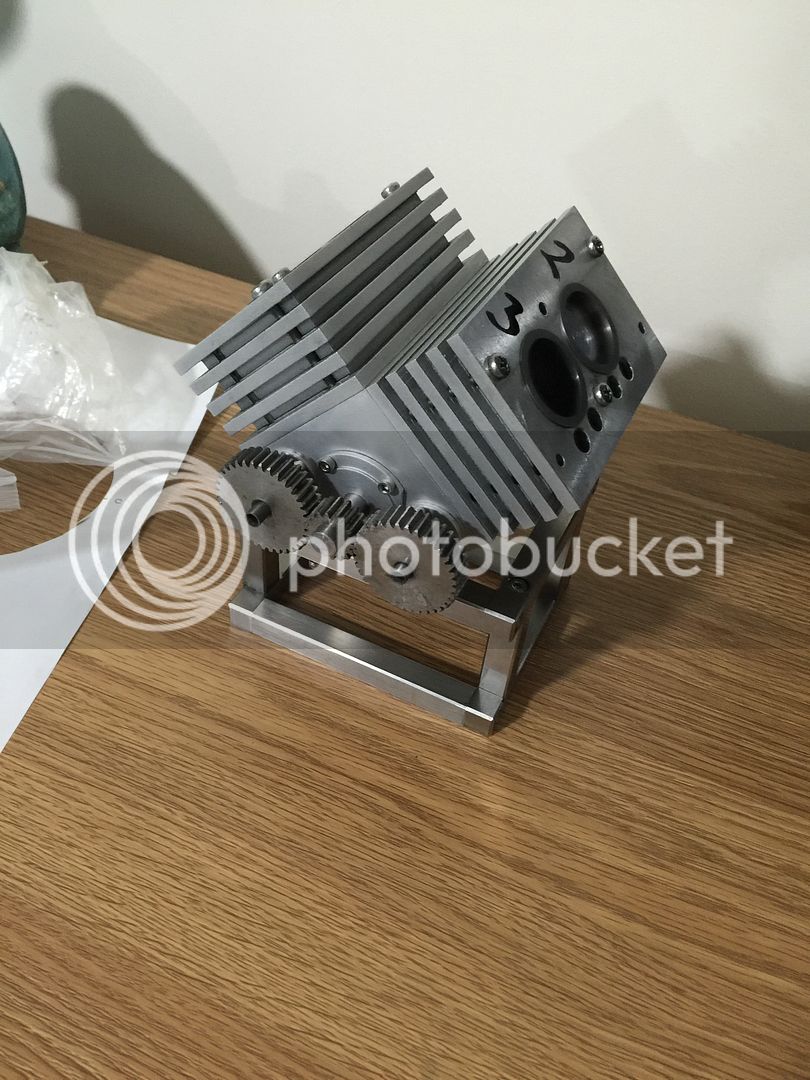
Used a wood router bit to put a chamfer on the top edge of the heads. Works very well. I was going to mill the outer side of the heads where the exhaust manifold would go, just to change the angle as it's flat from the block all the way up, but the shape is growing on me.
Mounted the rotary table to the mill to create 'spokes' on the cam gears also.
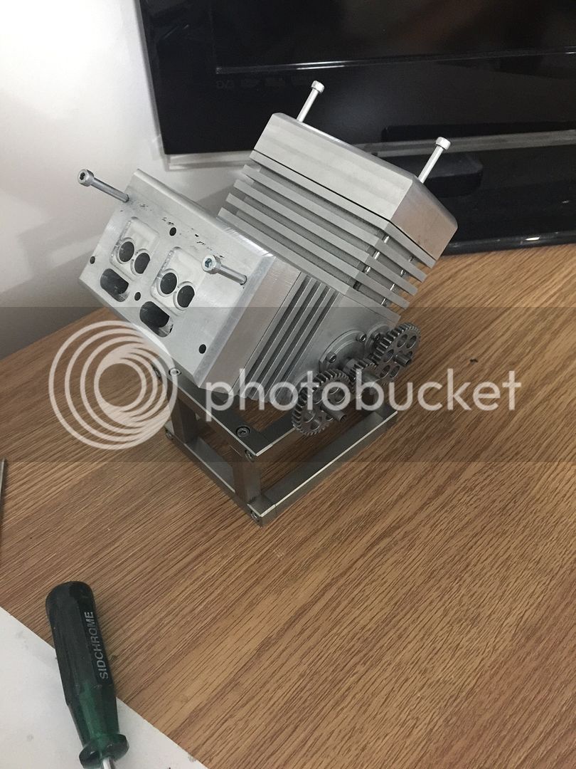
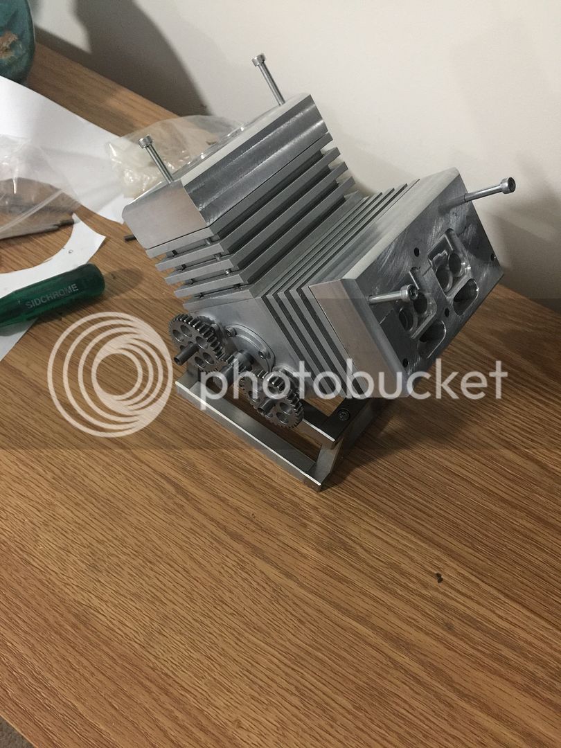
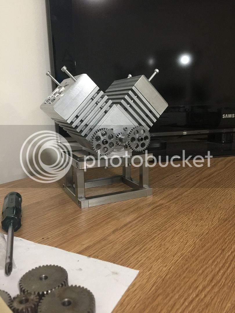
Mounted the rotary table to the mill to create 'spokes' on the cam gears also.


- Joined
- Dec 9, 2015
- Messages
- 327
- Reaction score
- 349
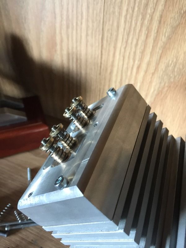
Progress is slow at this stage. Up until now everything went smoothly. I made 8 valve cages and destroyed four while pressing them into the head. Removing the cages wasn't a problem, but now I need to make another four. I successfully installed the other four.
Reason for destroying the other four was relying on a cheap set of verniers and not using a micrometer. They were far too over sized for a press fit and ended up crushing under force. Lesson learnt. I also disassembled the engine to remove the crankshaft and cut a key way.
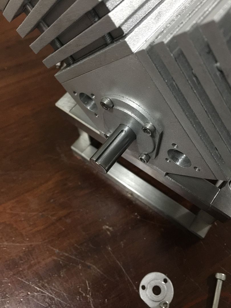
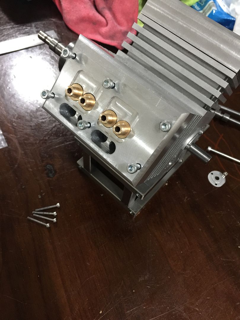
Reason for destroying the other four was relying on a cheap set of verniers and not using a micrometer. They were far too over sized for a press fit and ended up crushing under force. Lesson learnt. I also disassembled the engine to remove the crankshaft and cut a key way.


- Joined
- Dec 9, 2015
- Messages
- 327
- Reaction score
- 349
Gday bigrigbri
I haven't yet measured the head combustion chamber, but if it is 1cc (good chance that it's less than this), then the engine will have a compression ratio of about 8.5:1. But it's easier to lower the ratio than raise it so all is good.
Cheers
I haven't yet measured the head combustion chamber, but if it is 1cc (good chance that it's less than this), then the engine will have a compression ratio of about 8.5:1. But it's easier to lower the ratio than raise it so all is good.
Cheers
- Joined
- Dec 9, 2015
- Messages
- 327
- Reaction score
- 349
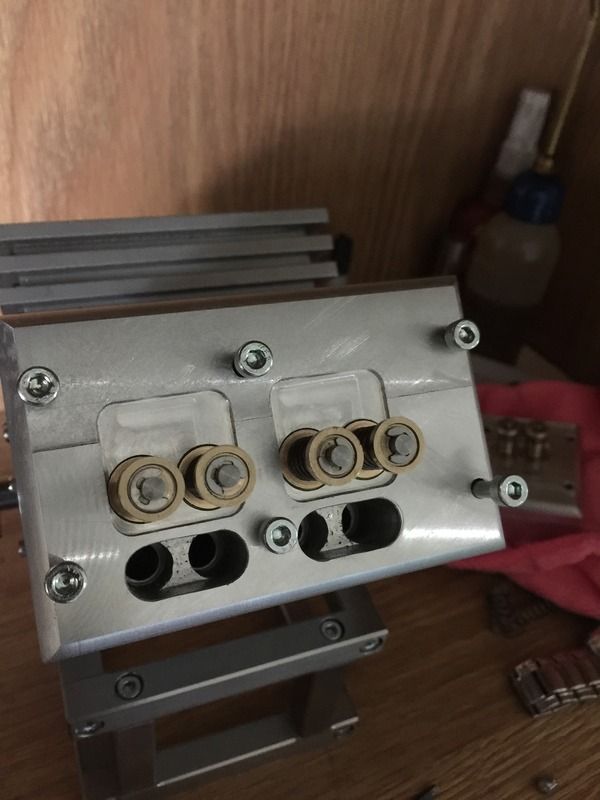
Valve cages are completed. This time around the evolution went very smoothly. Next I'll drill the nessessary ports and spark plug holes. Will be using 1/4 32 thread spark plugs that are used in RC aircraft.
I'm looking forwards to making the exhaust for this thing. I have some stainless tube that has 1mm wall thickness but bends relatively easy by hand. Is silver soldier the choice material for brazing? Will it hold up to the temperature? Previously I used nickel/silver rods but this needed a much much higher temp to melt, so looking for an easier option.
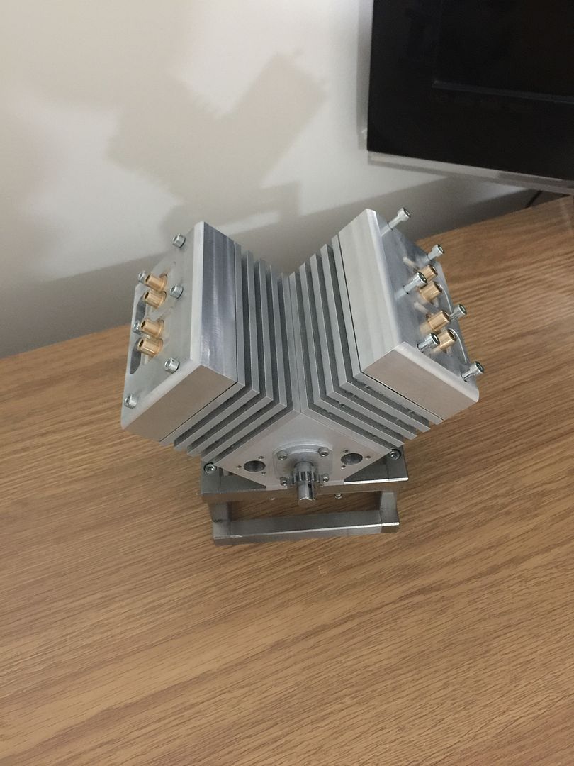
I'm looking forwards to making the exhaust for this thing. I have some stainless tube that has 1mm wall thickness but bends relatively easy by hand. Is silver soldier the choice material for brazing? Will it hold up to the temperature? Previously I used nickel/silver rods but this needed a much much higher temp to melt, so looking for an easier option.

Parksy,
Maybe I missed it, but I didn't notice any mention of a plan to liquid cool the engine. I'm wondering about the current lack of even cooling fins on the heads which is where the heat will really be generated. A multi-cylinder engine is going to create more heat than a single cylinder, and it will be much more difficult to get that heat out. And so, expect the temperature to rise very quickly - within tens of seconds. You'll at least have to consider this in the selection of your engine's clearances as well as your method to insulate the carb and induction system. So far, it looks like your exhaust will be the major escape route for the heat, and that may not be enough even with an external fan blowing over the engine. Have you seen any running examples of an air-cooled V-4?
I certainly admire someone who can make up their design as they go. It's never been something I've been able to do. My scrap pile would already have contained more parts than the engine. Best of luck. - Terry
- Joined
- Dec 9, 2015
- Messages
- 327
- Reaction score
- 349
Thanks for the post Terry. You are correct about the lack of liquid cooling as i haven't added provisions for this. Once I've finished all the necessary ports and rocker mounts I will be working out how and where I can mill some cooling fins into the heads. I really should have given more thought to this, and it is something I'll be monitoring if it decides to fire up.
- Joined
- Dec 9, 2015
- Messages
- 327
- Reaction score
- 349
I remember when I first tried making valves(almost a year ago), I thought it was the most frustrating evolution ever. I couldn't get it right and had issues getting the stems parallel due to being so long and small in diameter. But now I find it a satisfying evolution and can produce consistent valves that I'm happy with, thanks to the advise given by members on this site. Thank you!
These are made from 303 stainless. I'm used to 304 or 316, but 303 is just wonderful stuff. So easy to machine.
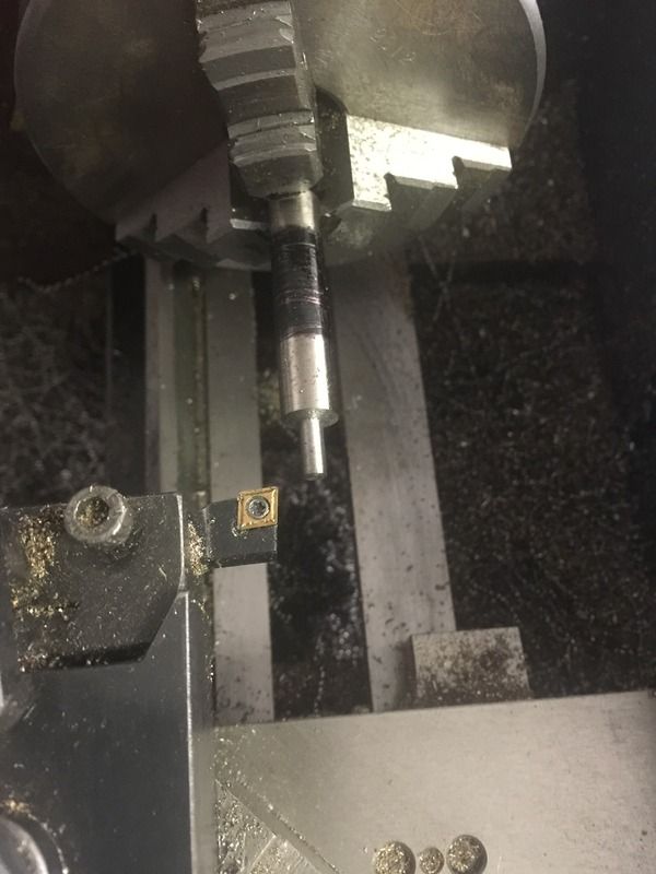
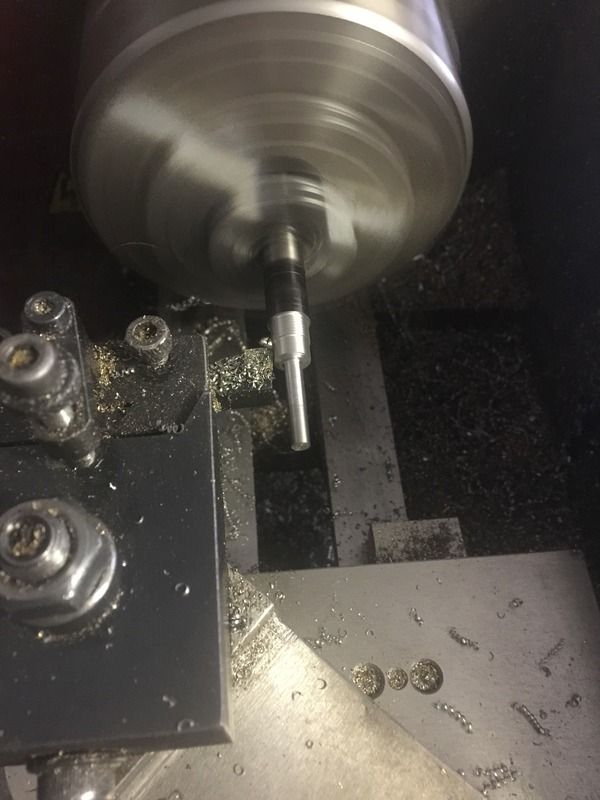
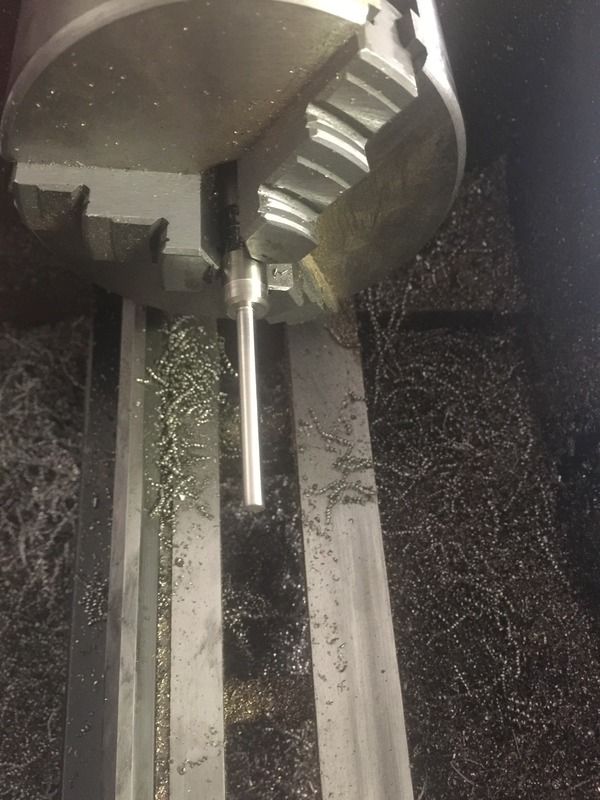
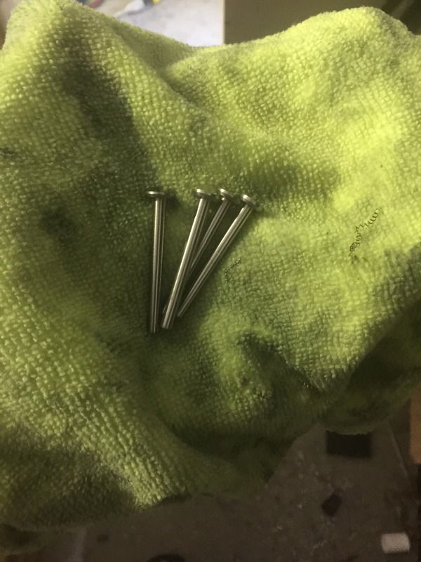
These are made from 303 stainless. I'm used to 304 or 316, but 303 is just wonderful stuff. So easy to machine.


ZebDog
Well-Known Member
Nice work on the valves
I used e-clips on my Webster works a treat
I used e-clips on my Webster works a treat
- Joined
- Dec 9, 2015
- Messages
- 327
- Reaction score
- 349
Drilled, counter bored and tapped the spark plug holes. Ports drilled within the heads. This part seems to always make me nervous but went well without drilling into any 'vacant' spots within the head.
The entire build I've been looking forwards to making some headers, and a couple hours of work and it's almost done. Still need to braze it together and clean up the ends.
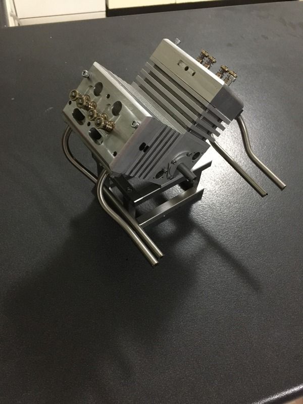
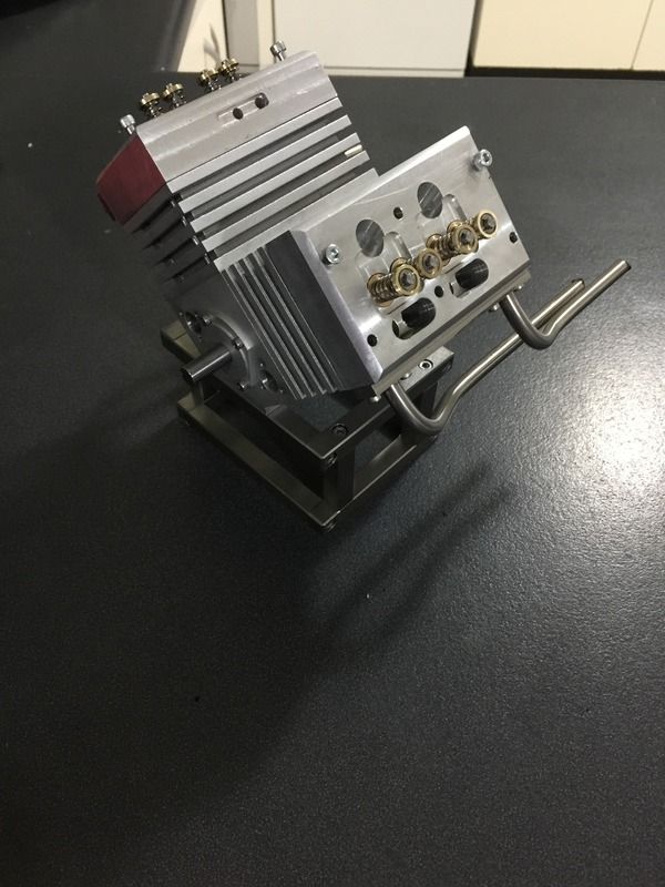
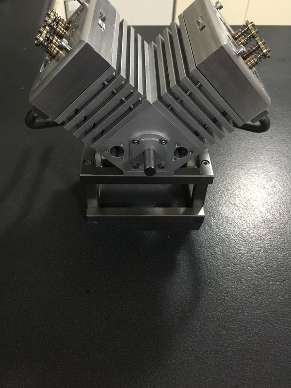
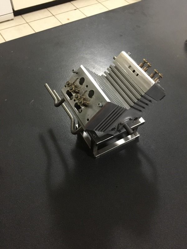
The entire build I've been looking forwards to making some headers, and a couple hours of work and it's almost done. Still need to braze it together and clean up the ends.


Similar threads
- Replies
- 6
- Views
- 3K
- Replies
- 205
- Views
- 30K


