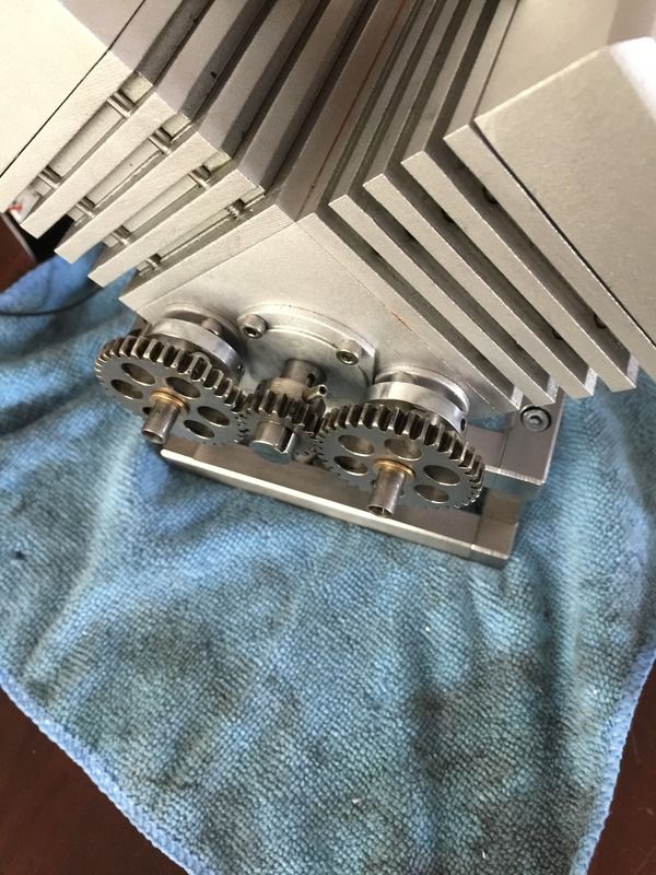
Parksy's v4

Home Model Engine Machinist Forum

Help Support Home Model Engine Machinist Forum:

This site may earn a commission from merchant affiliate links, including eBay, Amazon, and others.
Parksy, looking good, you're a fast builder.
You really have that nickel plating down pat, parts look nice.

When you were talking about oil sump & ignition & such I assumed this to be a gasoline engine. But now I'm eyeing methanol carb & threaded plug holes, but hard to judge scale. What's your plan?
 
Thanks Petertha.

It will be spark ignition and I have some 1/4" 32tpi spark plugs ready to install. The carb is a methanol carb, and I will try to start the engine on this type of fuel. My other engine starts really easily on methanol fuel, plus apparently it runs cooler than petrol? Or so I've been told. But at the end of the day I haven't made it to run on any particular fuel, the carb was just available to use.

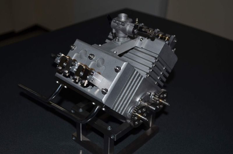
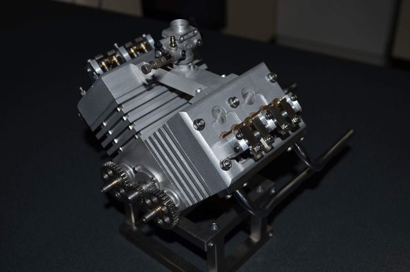
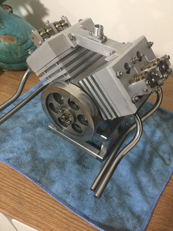
I've sand blasted the heads and intake manifold so it doesn't look so mismatched. I also managed to remove the black stuff from the exhaust manifolds post brazing. I'm happy with how it's turned out. I also had a play with another camera to try and take nicer photos.


Parksy,
If I might make a suggestion. Make some insulator blocks for the ends of the intake manifold. These can be made from Corian, Teflon or some similar material. What will happen when you get the engine running is the heat from the heads will heat up the manifold and then the carb. Once the carb gets warm enough it will boil the fuel out of it (vapor lock) and the engine will stall and won't be able to be restarted until it cools.
I had to do this on my V-twin engine.
gbritnell
 
Good idea Gbritnell. I didn't even think about this, but shouldn't have any problems with fitting some insulators.
 
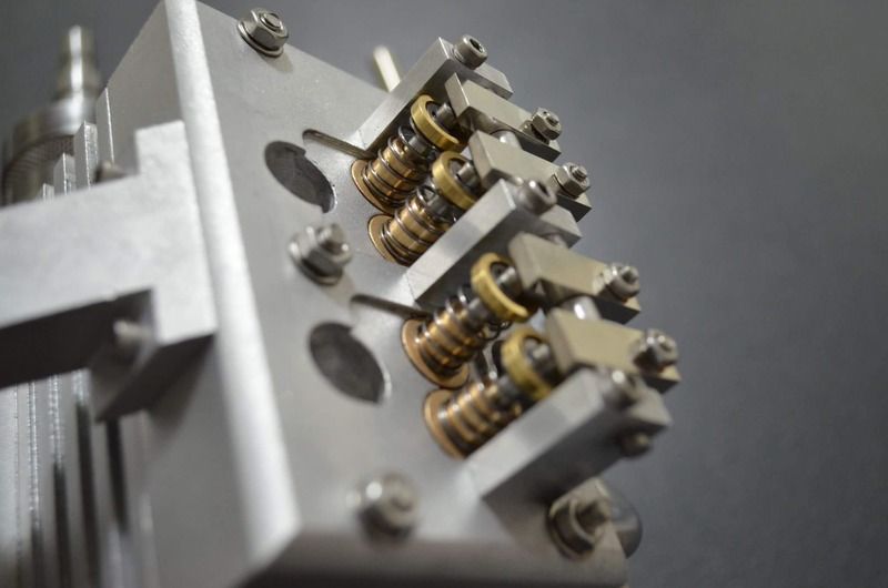
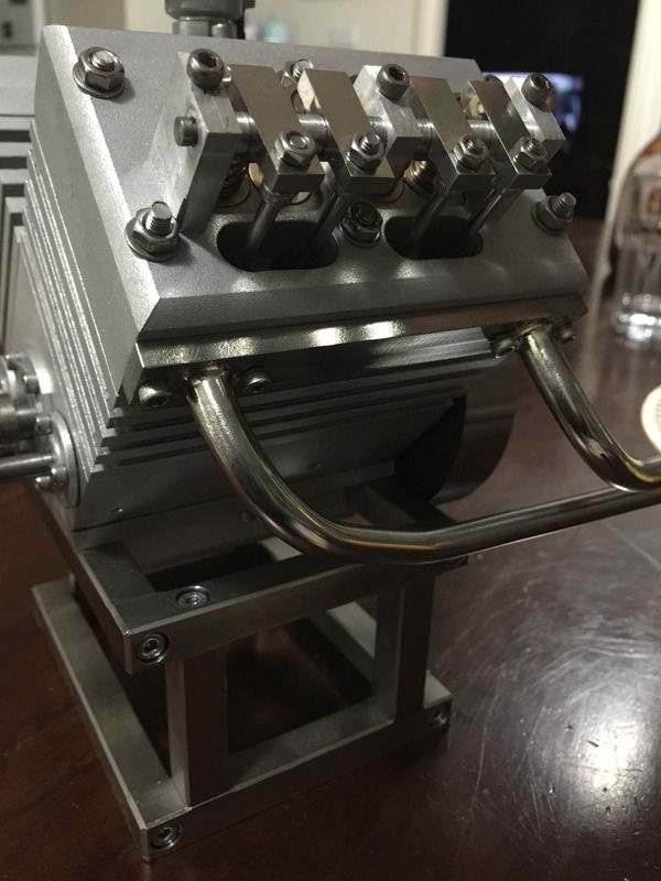
Pushrods are completed. There's nothing to them, they are just 1/8" stainless rods with the ends rounded. One end fits into the lifter and the other into a hollowed out hex screw that I use for adjusting valve clearance.
The pushrod on the very left was the first one I made and is slightly too small as the screw is unwound far too much. Easy fix.
Can see in the pic a flywheel that I started ages ago. It started off as flat bar I've turned it down but still need to hollow out the inside section. I'd like to make a flywheel with straight spokes, and I've got a basic idea on how to do it, drilling out the corners of the spokes then using an end mill to remove the bulk. I've never tried it before so I'm keen to learn a new trick.
 
Cheers Gordo. Appreciate the kind words.

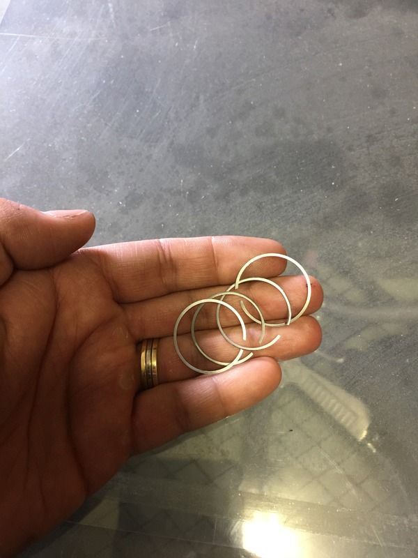
The engine is ringed now. Picture only shows four piston rings but I've installed two rings per piston.
One issue I always come across when making rings, is what depth I need to put into the piston itself. I made the rings 1mm thick and put a 1.1mm depth on the Pistons. But despite this additional clearance, I found myself having to increase the depth on the Pistons slightly and spinning the ring in its groove with wd40, to wear it in so to speak before it fit would fit in the cylinder. What depth on the piston should I aim for if I make 1mm thick rings?


The rings add a little extra resistance and I'm tempted to run them in on the lathe. But from the advice given on here, I should avoid this until I want to start it.
 
Parksy, will have to see if I can find my old Kent's Mechanical Engineers Book, it will have it in it, been a while since I have done piston and ring sets. Love the build, following along.

Cheers
 
Parksy,
I use about five thousandths clearance between the back of my rings and the piston. If your ring isn't going down in the groove completely your grooving tool may not have had sharp enough corners for the edges of the rings, or there could be a burr left on the ring. - Terry
 
Parksy, Looked in the book, generic setup 6thou/inch bore back of ring to ring grove base (Refer OEM spec's) Ring grove would be 12thou less that the inner ring dia as fitted in the cylinder. Due to the small size of these engines a lot of these settings may be too much clearance. Hope this helps:)

Cheers
 
Parksy,
I was doing some engine work this arvo, measured some rings and piston sizes on a 39mm piston, ring thickness 1mm, width 1.7mm, ring grove depth, 2mm, gives a clearance of .3mm(11thou), this is on a 38cc F/S spark ign petrol burner.
Just for you info.

Cheers

2.jpg


3.jpg


4.jpg
 
Thanks for the info guys. This gives me a good idea on what I should be aiming for.
 
Borrowed a flywheel from my last engine. The engine has been assembled for the final time and sealed accordingly where applicable. I've started working on the ignition side of things, really not far to go.
 
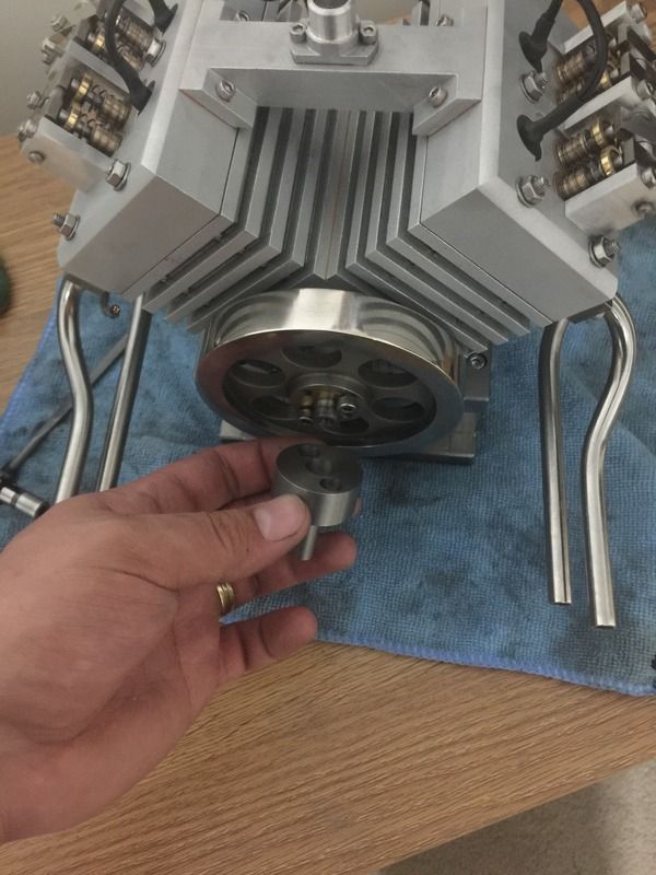
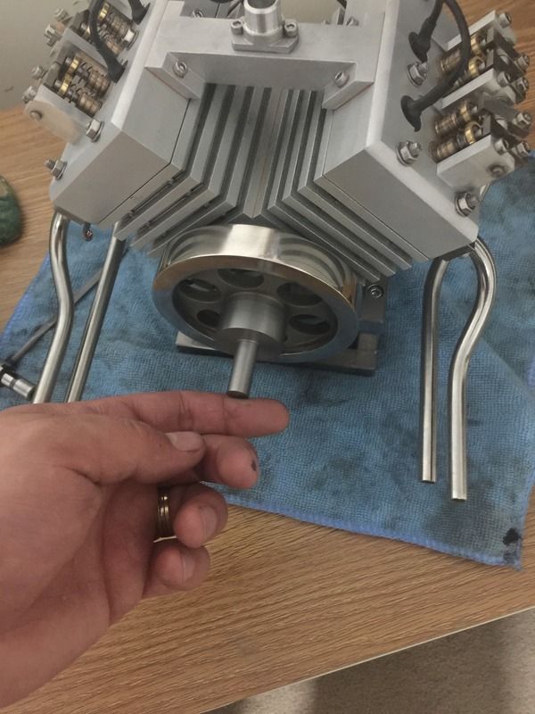
Needed a way to drive the engine for start up, so came up with a very basic tool that fits into the chuck on a battery powered drill and drives the flywheel end of the engine.

 
I have mounted some hall sensors to the engine and made some discs out of aluminium that contain two magnets each. The ignition system I chose has a red LED which is handy to test that I've installed the magnets the correct way around and also for timing purposes.

If things go to plan, I may attempt a start tomorrow.
 
Attempted a start today, but no success. I suspect I may not have enough compression to make it self sustaining as it appears to run ok while driven by the drill. But I'm one step closer to the end result. I've made a quick video to show what happens when trying to start. I've got it hooked up to a rudimentary vapour carb but the results are fairly similar when using a regular carb. I just wanted to see if I got a different result.
https://youtu.be/qgs4-WdlHmI
 
Well the more I try to run the engine the better the compression gets, so I don't think this is the problem. I think it could actually be a breathing problem, but with the crankcase. I drained the oil and spun the engine by hand and saw bubbles emerge from the drain hole. I'll make a breather when I get the chance. Thinking of utilising the oil filler screw for the breather tube.
 
Well I tried running it without the oil fill plug. There was pulses of air shooting out of the port and the engine spun better. But still no start.

My suspicion is now with the wasted spark setup I've got. One cylinder has the wasted spark while exhausting, but the other cylinder has the wasted spark while it's beginning its intake stroke. This could explain the puffs of fuel I'm getting from the carburettor.
I just need to find a cylinder combination where I can have the wasted spark at a satisfactory timing, but with a 90 degree block and a crankshaft with two throws 180 degrees apart, I'm not sure if this is possible. If anyone has any suggestions, I'd appreciate it very much!
 

Latest posts

Back
Top