Model Sawmill Dreaming---

Home Model Engine Machinist Forum

Help Support Home Model Engine Machinist Forum:

This site may earn a commission from merchant affiliate links, including eBay, Amazon, and others.
Some days you eat the bear and some days he eats you :)

Still great progress and thank you for sharing it.

Pat
 
Bret--Right now the blade is just straight up and down. However, I can easily change it over to an angle if that works better. I am fumbling my way along here, with no prior knowledge of this type of mill. I seen one once, must have been 30 years ago, and I don't think it was operating. Any knowledge I have currently has been gleaned from Youtube videos.
 
I went back thru my engine files, and I was mistaken about bore size. The Kerzel hit and miss is the smallest, at 0.75" bore. The Webster is larger, at .875" bore, and the Atkinson is the largest, at 1" bore. For the (very brief) time that I had the Atkinson engine running the sawmill this afternoon, it was really wailing away with no apparent strain on the engine. The Webster seemed to be working fairly hard. Now that I know that my Kerzel hit and miss engine is the smallest bore of the lot, I may have to rethink which engine I will run the sawmill with. The Atkinson is just a funky enough engine that it would have great eye appeal when set up to run the sawmill, and no lack of power either. Since both the cylinder and the piston on the Atkinson are made of grey cast iron, I don't know if the threat of overheating is real or not. The other thing is, I don't plan on going into the sawmilling business, so to start the engine and run it for 15 to 20 minutes at a stretch to saw a log may not be that big an issue.
 
Nothing accomplished today---I'm sick!!! Grand daughter brought home something really nasty from kindergarden. Both her parents are sick. Her other grandmas sick. My wife's sick. Now I'm sick. Of course granddaughter is better now. Shivering, shaking, upset guts. Damn I hate being sick!!
 
Too sick to work.---Not too sick to CAD!!!
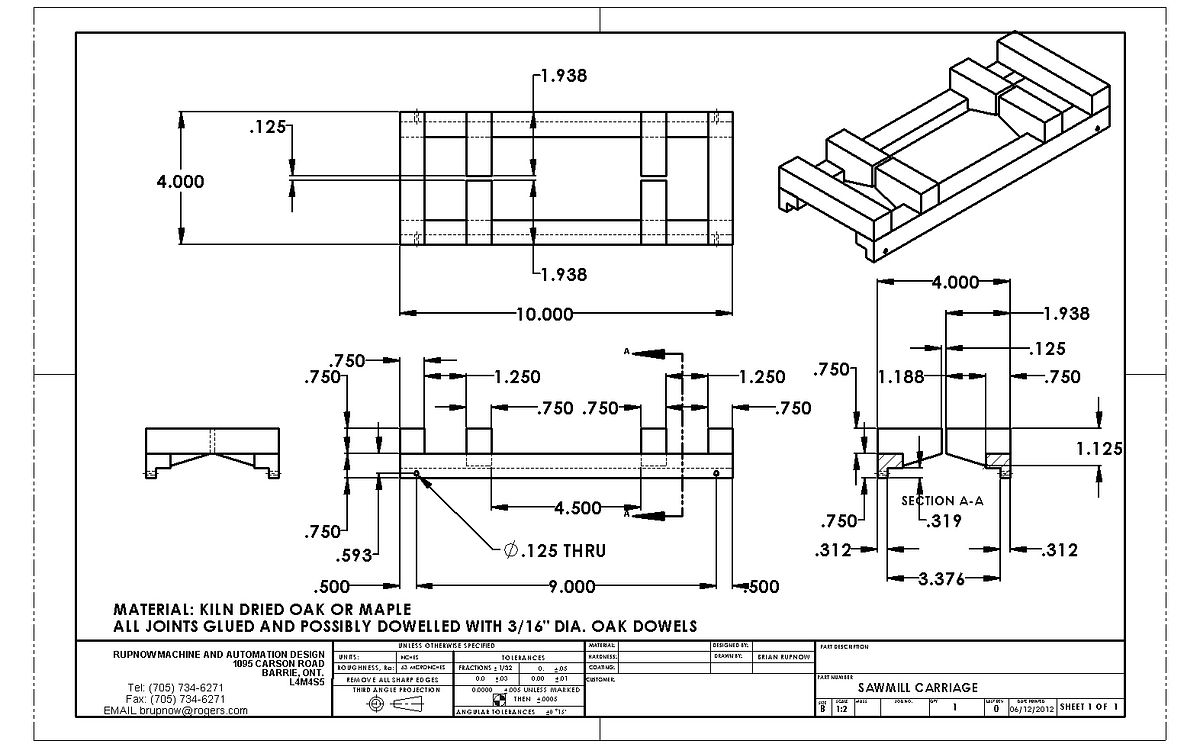
SAWMILLCARRIAGE-1.jpg
 
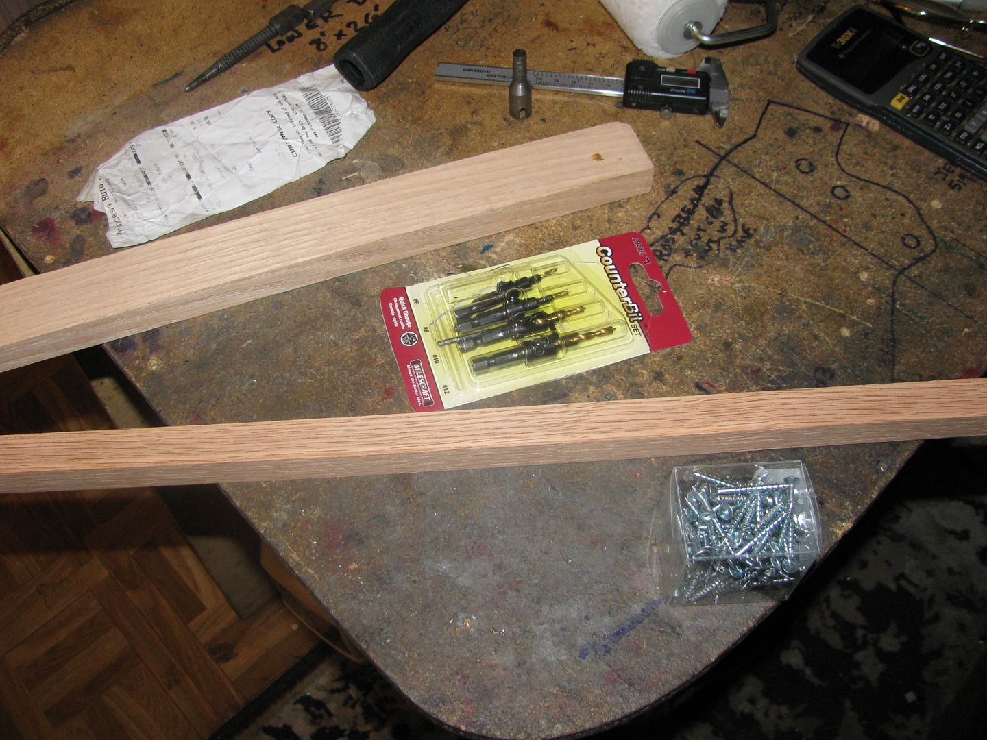
This morning I bought the material to build my carriage. Total cost was about $3.00 at a local trim and molding supply house. then I went to BusyBee tools and bought some drill/countersink combinations to work with #6 woodscrews. I have realized that by screwing from the underside, all of the woodscrew heads will be hidden after the carriage is mounted in place. I will glue all of the joints as well, with Elmers wood glue, but I have always had a basic mistrust of glue, based on the fact that everything I ever glued together with no other mechanical fasteners eventually fell apart. Big John--I will go back and look at the video again.
CARRIAGEMATERIAL001.jpg
 
I have been criticized (lightly) by someone on another forum because my model doesn't exactly match their vision of what this type of mill really looked like.I just went back and looked at the file of pictures someone posted of an old mill. I see what they mean about the end members on the carriage having sawcuts "Just deep enough". I have seen other videos where the carriage set-up is very similar to what I have designed. The models I build are not true "scale" models. They are representative of old machinery, and I do take some "license" with the design, either to make it easier to manufacture or to the design I would have made if I had been the engineer at the time. Please don't take offence if what I model is not exactly what you may have seen. I post all of my design drawings, and if someone else wants to use them to build a working model and change any of the drawings to a design that pleases them better, then that is perfectly acceptable to me.---Brian
 
Considering you never claimed to be making a "reproduction" I think your work is fantastic. Anybody, with enough patience, can copy a design, it takes a genius to derive a design.

Thank you Brian for all of your derivations, I find them very educational.

Pat
 
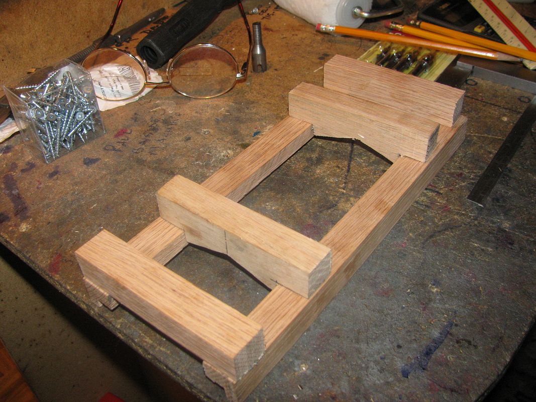
And here we have a carriage.--At least here we have it with all peices sawn out and mocked up into an approximation of what it will look like when all screwed and glued together. The two crossmembers closest to the center will be left solid untill they are actually cut by the saw in the sawmill. Now for a bunch of glueing and screwing. I have to say, at this point, that the accuracy of my $25 yard sale tablesaw leaves a great deal to be desired!!!
CARRIAGEMOCKEDUP001.jpg
 
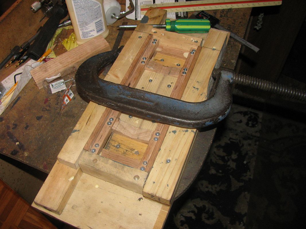
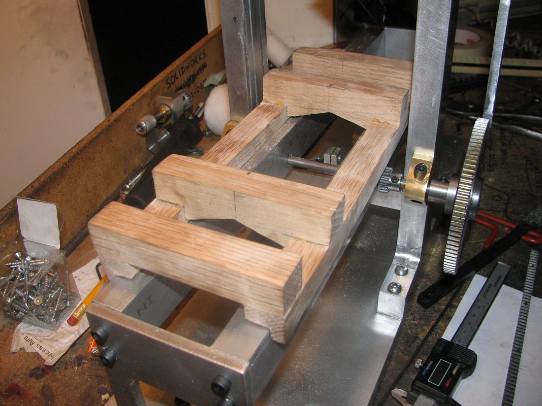
Nasty, tricky damn stuff, that wood is!!! I couldn't figure out how to hold everything square, drill it and screw it together all at the same time.So---I used half a cord of wood scraps to build a jig to hold everything in the correct relationship while I did it. Now, if I have lived right, (cough! cough!) in the morning when I dismantle the jig from around the carriage, it should all be perfectomundo. I really hope that none of the 16 screws come thru the top side of the jig. (They're not supposed to). I know that some of the heads are a bit proud, but I will either mill or grind them down flush to the surface of the wood after everything has set up. I didn't want to tighten them so much that I split any of the hardwood.
CARIAGEINJIG001.jpg
 
Now I get to wear my dunce cap. I was just looking for something in my shop and I see a note on the wall that I had written to myself at some time in the past. It says"Atkinson-counterclockwise-----Webster-counterclockwise-----Kerzel hit and miss--CLOCKWISE!!! I couldn't get the Kerzel to start earlier this week. Now you know why. I was turning the friggin thing the wrong way!!!
 
Dont feel too bad Brian. At least your engines turn :rolleyes:
 
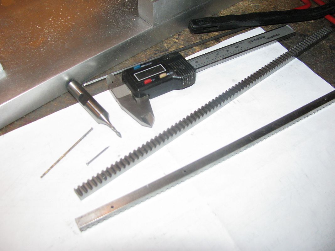
The carriage turned out splendid!! None of the 1" x #6 woodscrews came thru the top, and the squareness tolerances came out well within "Rupnow Limits". Up until about an hour ago I had no firm plan in place for attaching the steel racks to the underside of the carriage. A quick root thru my cupboards unveiled some very small nails, with a diameter of .050" x 0.875" long with a head .079" diameter. I found a dia. 0.056 drill to drill thru the racks at the root of the teeth 5 places on the underside of each rack and then found a 2mm (0.080") dia two flute endmill to act as a counterbore and allow the head of the nail to be down below the surface of the root of the gear rack. Last but not least I scrounged up a dia 0.045 drill to pre bore the hardwood of the carriage before nailing the racks in place. As a security measure, I will spread a thin coat of 5 minute epoxy between the rack and the hardwood before setting the nails.
RACKANDCARRIAGESTUFF001.jpg

RACKANDCARRIAGESTUFF002.jpg
 
Last edited:
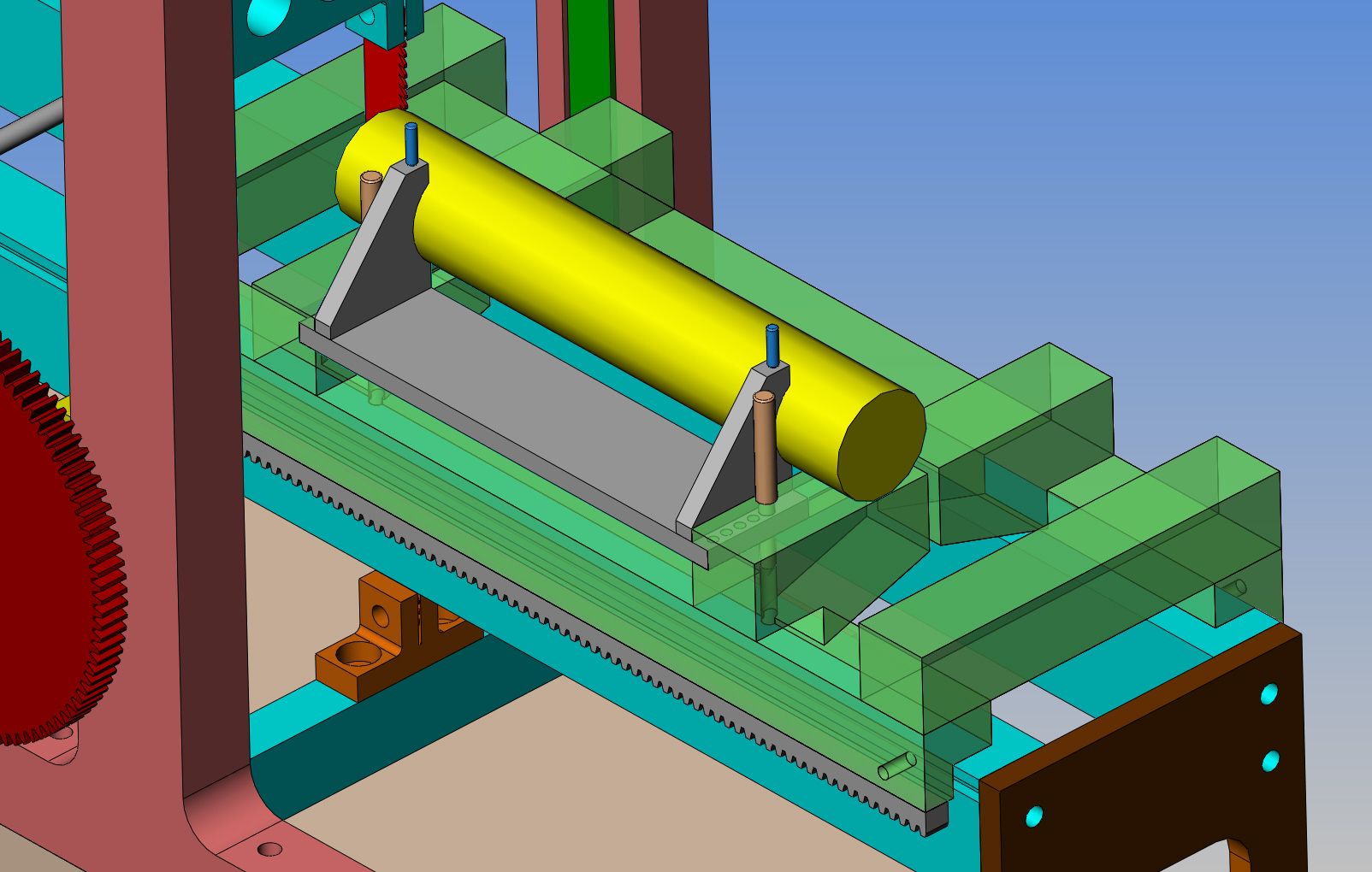
There comes a time in every project like this, where you have to do something that you are not absolutely sure how it was done originally. Or perhaps you do know, and either you don't like it or consider it too much work to exactly replicate. I am at that stage now. I have to hold the "log" to the carriage securely while it is cut, but I still have to be able to advance whatever mechanism is holding the log in even incrememts so that I can saw boards from it. My "boards" will be 0.150" thick, a number I have arbitrarily picked.The grey colored mechanism which actually holds the log will be made of aluminum, purely because I have lots of it. The "log" will be pre-drilled to accept 2 "pins" (the blue colored ones) which pass thru the log holding mechanism and thru the log as well. they will be made from cold rolled steel, and the shank will be 0.030" diameter--They are not hammered into place---just a good fit.. That looks after securing the log. You can see that the grey log holding mechanism fits into slots in the carriage beams. This log holding mechanism has a series of holes in each end, drilled 0.150" apart. the light brownish pink colored pins pass thru a clearance hole in the carriage beams and thru the appropriate hole in the log holding mechanism. This is what allows me to "set the log over" in 0.150" increments to cut boards. Will it work?--Yes of course it will. Is it an authentic reproduction of anything?--No, of course it isn't.
LOGHOLDINGDEVICE.jpg
 
Lookin good Brian,

It's going to be a treat seeing it run by one of your engines sawing away!

Thaks,
Dave
 
Brian,
Your approach to your models is to be commended. True they aren't exact replicas but work very well and are an inspiration to the rest of us. Keep up the good work sir. And thanks for sharing
Ernie J
 
Hi Brian,
I can't say I ever saw a mill like the type you are building in action but with the circular types the first couple of cuts were made on the log to produce a flat surface. The log was then rolled onto that surface to clean up the next side and so forth and so on until a squared up log was made. The actual board making process was then started. I would have to think that even with this earlier design a similar process would have been used otherwise the edges of the sawn boards would need to be run through this or another saw to square up the edges.
I'm assuming with what you have proposed to hold your 'log' down that you aren't concerned with squared edges but rather just cutting boards from the log.
I understand your mill is not prototypical but rather a very nice working facsimile but why not for the sake of operation just start with a squared up 'log'. That way it would be more stable and you could use a more simplified hold down mechanism.
Your mill is coming along great and I for one can't wait to see some boards produced.
gbritnell
 
Looking good Brian

Through and through sawing as we know it is where the log is not turned is quite common so no problem with teh way you have done things. The resulting boards are known as "waney edge"

flitch%20sawn%20pile.jpg
 

Latest posts

Back
Top