Kozo A3 in 1.5" scale

Home Model Engine Machinist Forum

Help Support Home Model Engine Machinist Forum:

This site may earn a commission from merchant affiliate links, including eBay, Amazon, and others.
kvom said:
One of our club members suggests an extra pair of mounting holes between the steam chest and the cylinder using countersunk screws. These would allow the cover to be removed without the steam chest itself moving. This sounds like a good idea. I'll wait to finish the cylinders as drawn before figuring out a cood place for these holes.

I would also suggest Drilling and Tapping two extra Holes in the Cover, one at each end. This allows two Bolts/Screws to be inserted in these Threads to jack the Cover off and break the Gasket/Sealer to allow removal later on. It saves having to hit the Cover with a Softface Hammer to try and break the Seal.

Murray.
 
that little divot on the cly sure sucks.pulled one similar a few weeks ago J B Weld to the rescue, you might give it a try since it's gonna be hid and not in a critical location.

Tom
 
Cyclinders are looking great. I definately like the idea of using castings over Kozo's way of using a large chunk of brass.

James
 
Kozo specifies bronze rather than brass, but CI would also work on the 3/4 scale version. Based on working with these castings, I think starting with 4" round CI would be just as easy to machine and would be about half the cost for raw material. That said, the casting quality is good and I have no complaints.
 
Today it was time to drill and mill the steam chest face of the cylinders. In addition to the 8 8-32 holes for attaching the steam chest and cover, I also drilled some holes to clean material out of the steam ports. This way the 1/8" endmill has less work to do.

large.jpg


Setting up, testing, and running took a couple of hours of shop time for the first one. Then the second took just about an hour.

large.jpg


Now just need to drill the passages and tap 26+ holes on each cylinder.
 
Another session drilling steam passages this morning and afternoon. The exhaust and inlet holes went well, as seen here:

large.jpg


I was a bit nervous drilling at first, but I'd triple checked everything. I was glad to feel the drill bits ending up where they are supposed to.

Later this evening I drilled the first pair of steam admission holes. One came out a bit high in the port, so I need to figure out if it can be enlarged any. I drilled these .125 to start, but in theory they should be .196.

large.jpg


large.jpg
 
With some expert advice over at HSM, I managed to finish the admission holes successfully. The main changes I did were using a 26 degree vs. 28 drilling angle, and starting the hole with an endmill as a drill guide. Did successive drilling with 1/8, 5/32, and finally 3/16 using collets vs. a drill chuck.

large.jpg


So now just a lot of holes to tap. Did I ever mention I hate tapping?
 
Worked on the valves the past couple of times in the shop. I started with two pieces of 1.625" diameter phosphor bronze rod that I faced to final length of 1.32". For scaling Kozo's drawing a minimum diameter of 1.25" would work.

large.jpg


Next, I used a face mill on the Bridgeport to square the pieces to final width and height. Kozo mills andles on all 4 sides to fit the minimum diameter rod, but in this case I could have used the oblongs as is.

large.jpg


Nevertheless, I proceeded to mill the 45 degree angles on 3 sides. This does leave more volume in the steam chest for steam, so perhaps a good thing.

large.jpg


The valve pocket in the bottom I CNC-milled using a 1/4" endmill.

large.jpg


For the lengthwise slot that contains the end of the valve spindle, I notices that Kozo used a 2-56 thread and makes the slot .001 wider than the major diameter. I will use a 10-32 thread (diameter .19) so milled with a 3/16 endmill (.188). The resulting slot is wide enough to hold a 10-32 screw snugly. The cross slot can be any width as long as the nut fits securely. I used a 5/32 endmill and will machine the nut to match.

large.jpg
 
Today being "take your son/daughter to work day", my 14 y/0 was working with me in the shop today. Our project was the valve spindle yokes, pg. 103 in Kozo's book.

After rough cutting some 1/2" thick CRS on the bandsaw, Melinda was cranking the handles to square the pieces on the Bridgeport.

large.jpg


We then ran the CNC mill to create the profile, as well as center drill for the holes.

large.jpg


Back to the Bridgeport to mill the center gap of the yoke, then drill and ream the through holes:

large.jpg


After drilling the hole to mount the valve spindle, she tapped them 1/4-20.

large.jpg


The finished results, after about 3 hours:

large.jpg


She said she liked running the machines, but all the measuring and setup was a bit tedious.
 
Thank you for sharing. It reminds me of when My daughter use to play in my home shop. After many years I have her back only this time she has a corner with her art supplies to do her free lance graphic arts designs. Isn't Kozo outstanding ?
 
Having taken 2 weeks off for NAMES and then some minor surgery, I was eager to get back to work on the A3.

The first thing was tapping the 24 8-32 mounting holes for the cylinder heads. This went quicker than I expected as CI taps very nicely. I used the mill/DRO to position the tap vertically and start the first couple of threads, then finished with a tap wrench as usual.

I bought a piece of 3.5" brass rod at NAMES that I thought would make up the front cylinder heads. It was about 1.5" long but the ends weren't square. I mounted in the lathe, squared the faces, and then faced the spigots that fit into the cylinder bore on both ends. The resulting piece was now 1.32" long. Now I needed to split this into 2 thin discs. Starting with a 1/16" parting tool, it became obvious that this wasn't going to work, as the tool was flexing. I switched to a 1/8" blade and slowly cut using back gear and ~150rpm. When the diameter was down to 1", I cut the rest with a hacksaw.

Here's the result. The rest of the machining will be done on the CNC mill.

large.jpg


I also bought a piece of 4" diameter brass rod for the rear cylinder covers. I'm hoping it's long enough to part on the bandsaw.

I also
 
Recovering from surgery, I'm limited in what I can do in the shop (no lifting). So I have a backlog of stuff waiting until I can go full speed. Today I finished tapping all the holes on the cylinders: 8-32 for the steam chest and 10-32 for the tee/frame.

I also got my shipment in from Speedy Metals. A length of CI bar for making the steam chests, and two lengths of SS416 rod for the piston and valve rods, so those are now on the todo list.

I also tried out the 6-7 micrometer I picked up at NAMES for measuring the outer frame width vs. the length of the tee. I have about 3/8 to take off the tee so that it matches the frame. That way the cylinders, frame, and tee all fit together flush on both sides.
 
I was able to trim the tee so that it and the cylinders will fit flush to the outside of the frames. Then it was on to work on the steam chests. While these are relatively simple. I still put in a lot of hours over the past three days.

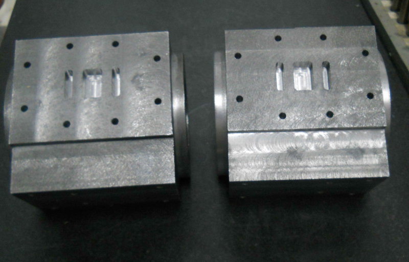
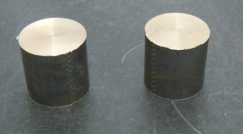
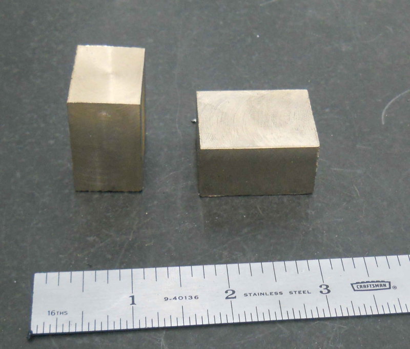
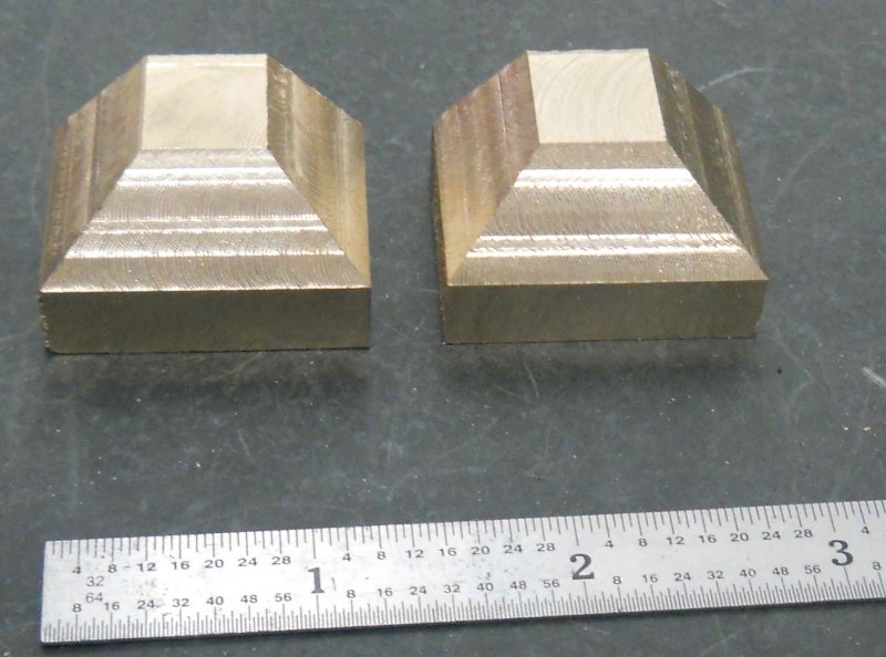
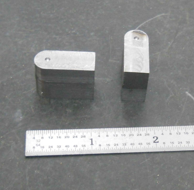
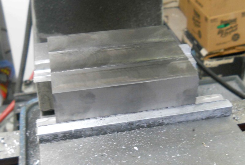
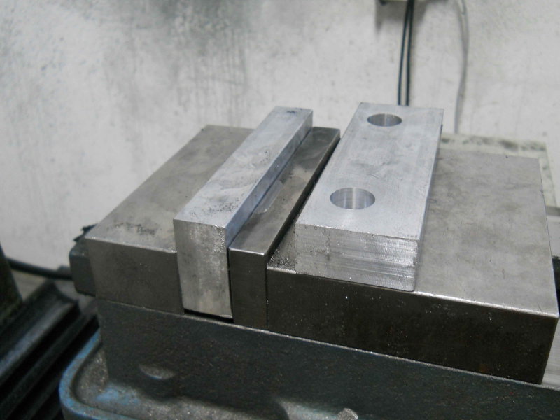
I had a 13" bar of 3.25x1.5 CI, enough for the two steam chests and a third if I screw up. After sawing into thirds and squaring each piece, I had a couple of these.

large.jpg


The bars are advertised to finish 1/4" less than the size. Since the chests are 2-3/16" wide, I would not have had much allowance with a 2-1/4 width. However, that meant a lot of CI turned into swarf.

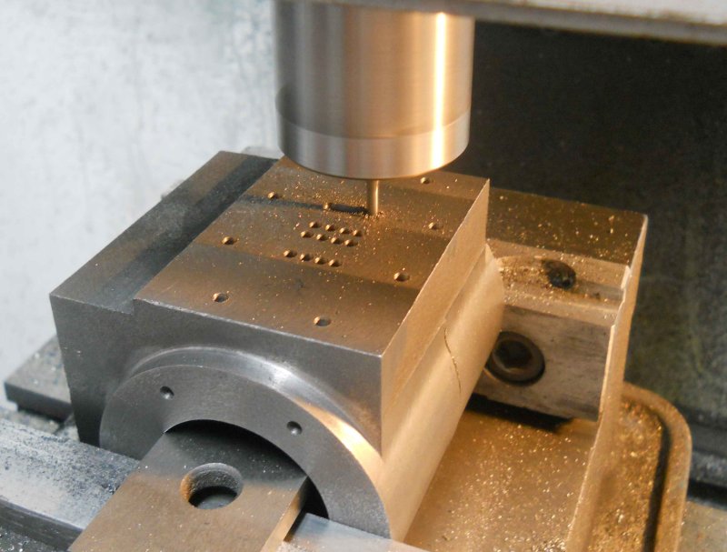
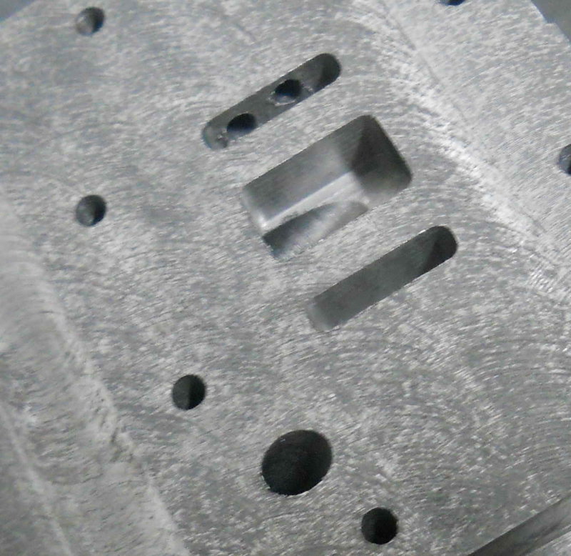
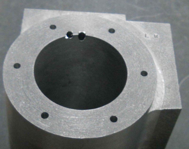
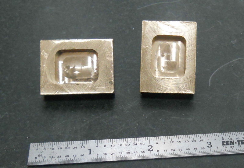
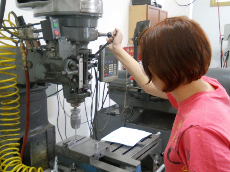
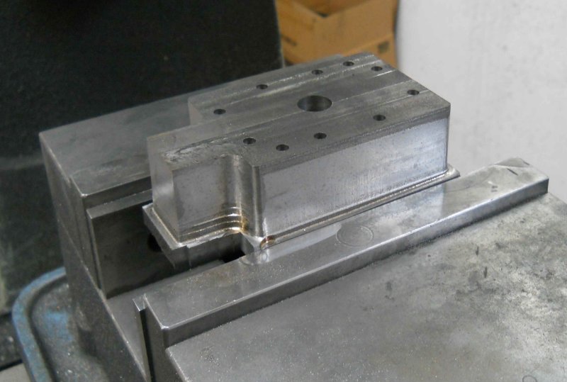
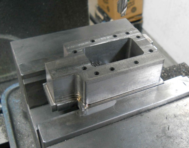
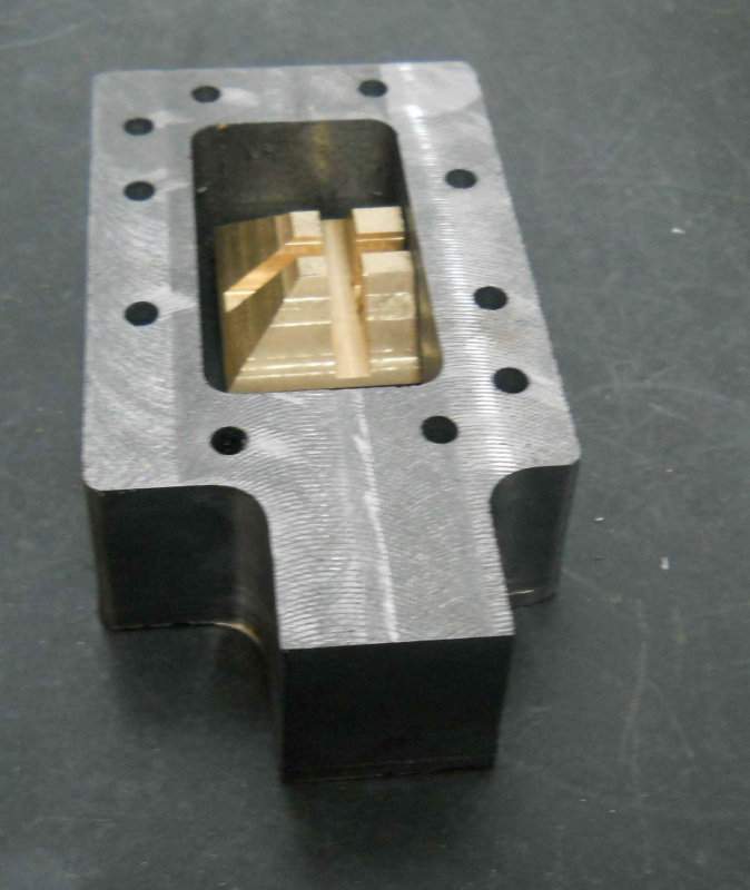
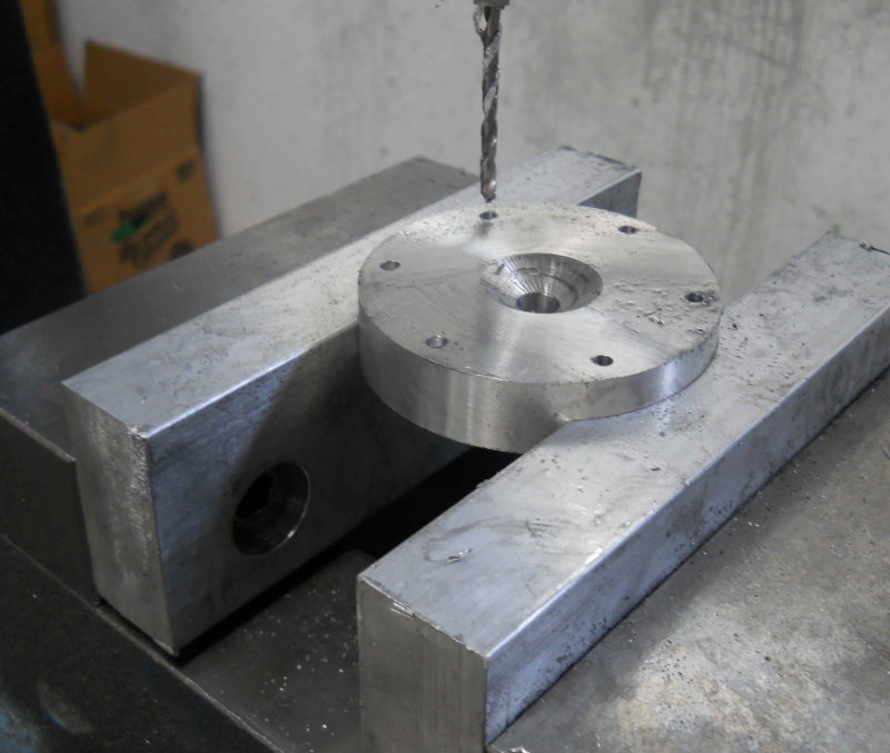
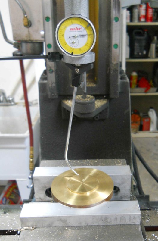
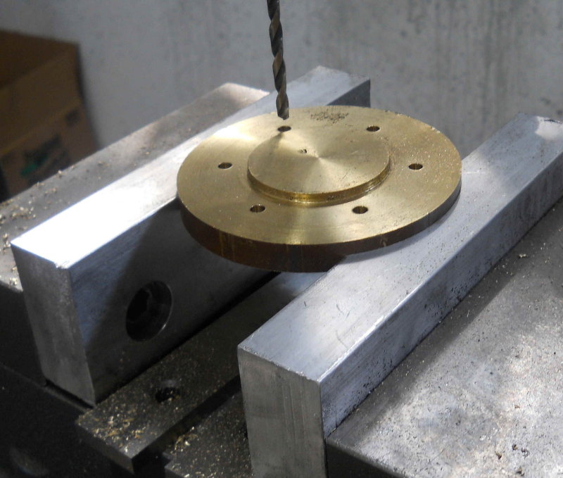
Next, used the CNC mill to drill the mounting holes and machine the outer profile. I added two additional holes which will attach to the cylinders but be countersunk and not go through the cover. These will allow the cover to be removed without the steam chest moving. The larger hole in the center is just to allow milling the center pocket with a non-center-cutting endmill.

large.jpg


large.jpg


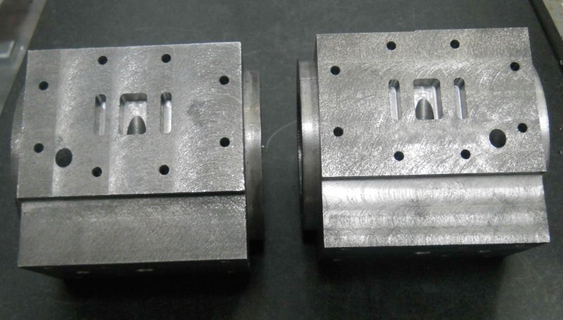
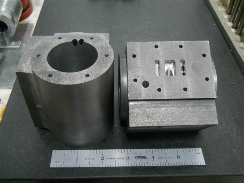
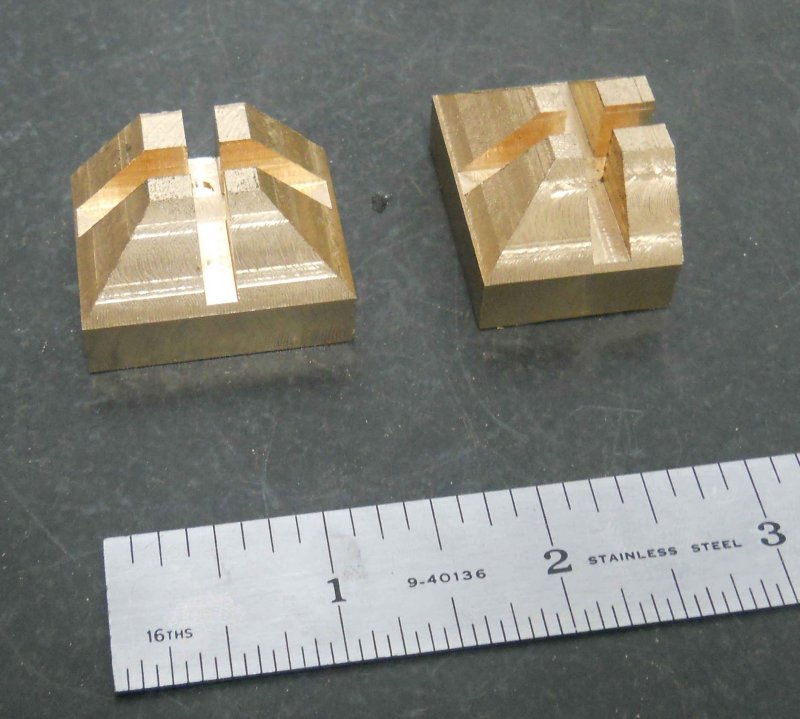
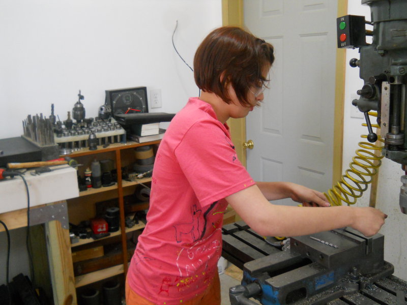
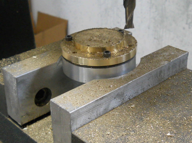
Next the bottom 1/4" is milled off using the bridgeport, leaving the steam chest 1" thick. The slide valve does appear to fit.

large.jpg


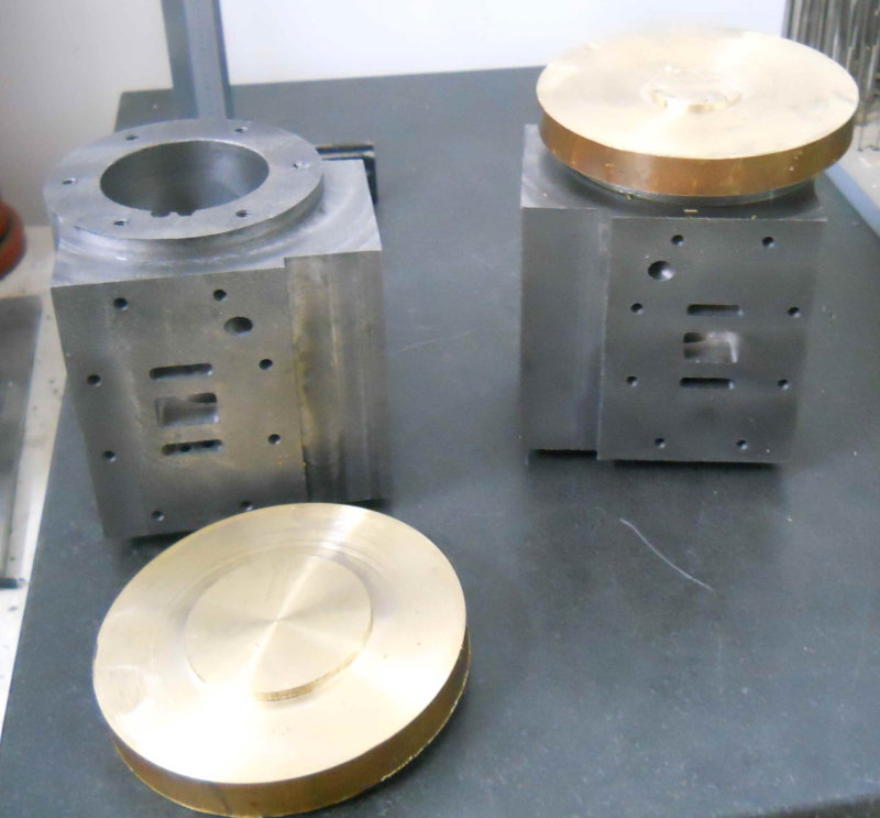
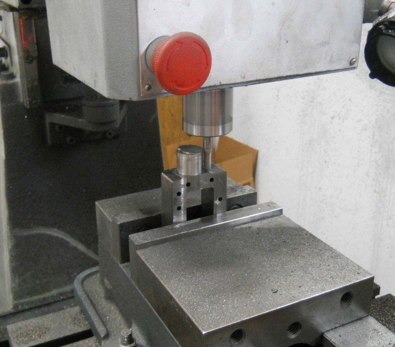
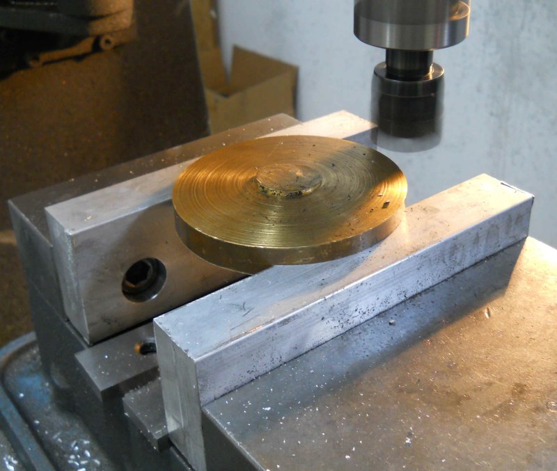
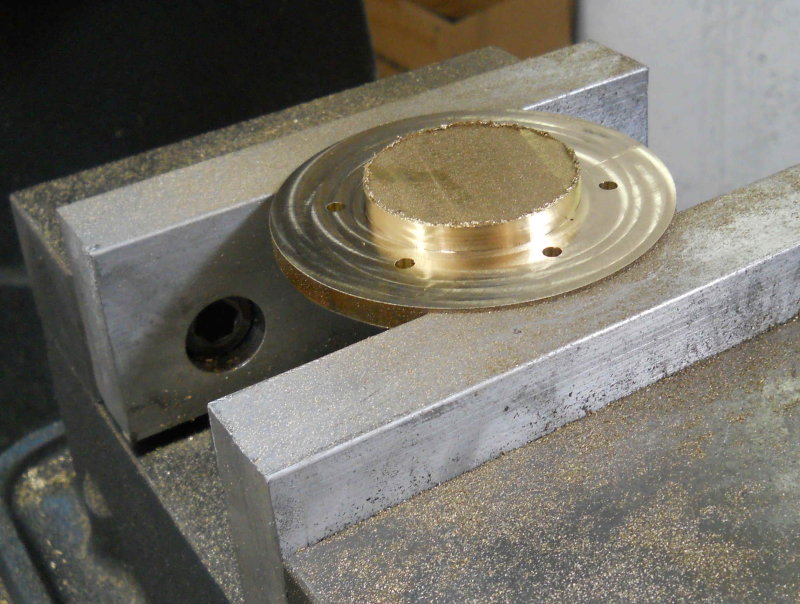
Rather than turn the spigot on the lathe, I used the CNC mill to do it faster.

large.jpg


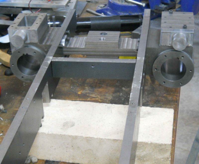
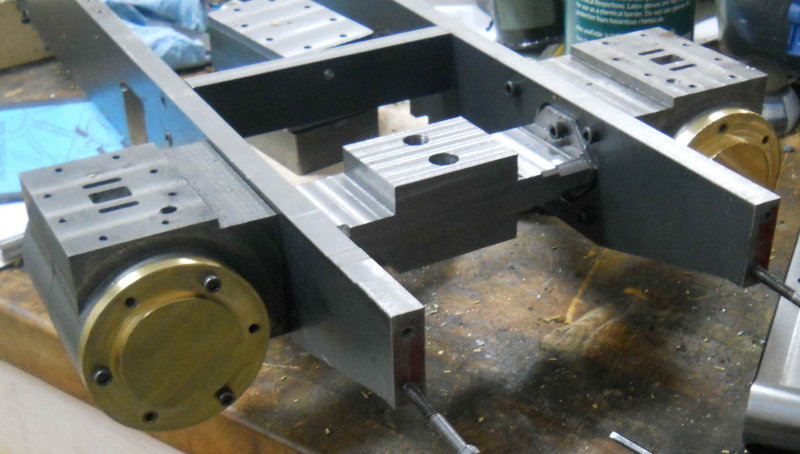
Finally today, put the tee and cylinders together on the frame. I had to trim the ends of the tee a bit as it's a close fit in the frame pocket.

large.jpg


Still to do on the steam chests:

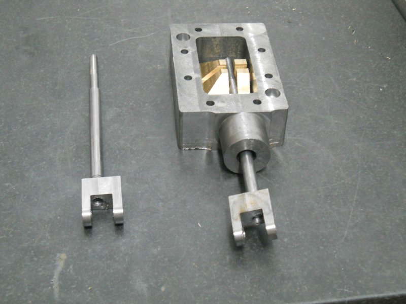
1) Bore a pocket in the spigot for the bushing (yet to be made) and o-ring, then the threaded hole for the bushing retaining screw.

2) Drill the hole for the valve spindle; I will do this with the bushing in place so that all is concentric.

3) Bore the passage in the inner wall to expose the steam admission port in the cylinder.

4) Countersink the two extra mounting holes


I spent the morning turning the valve spindles (fig 17-6, p. 103). Material is .25" 416 stainless rod. One end is threaded 1/4-20 to match the yokes my daughter helped make, and the other 10-32 matching the width of the slots in the valve.

Then it was fairly quick to countersink the two extra holes in the steam chest for 8-32 SHCS, using a 5/16 endmill.

Then I started work on the steam chest bore. The design here, as with the piston rod and axle pump plunger, is to seal the spindle with a Viton O-ring and guide the rod with a bronze bushing, which also acts to retain the o-ring within the steam chest spigot. For the valve, the o-ring is a size 2-010. Using Kozo's allowances on the 3/4 scale plan, I computed that the bore for the bushing needs to be .382 in diameter. I happened to have a .380 reamer acquired in an auction lot at a closed shop, so hopefully that will be close enough.

So the machine ops for the spigot, after centering on the Bridgeport, were:

1) Through drill a clearance hole. The closest drill I had is an F (.257)
2) Machine a flat hole .432" deep using a .375 endmill
3) Ream with the .380 reamer

Here's where I ended the day on the first chest. Once the bushing are made, I will drill/ream the .250" through hole with the bushing in place in the chest. It's not as critical to be concentric since the valve has "wiggle room", but for the piston rod I will need the bushing's hole to be dead nuts with the cylinder bore. I plan to use a similar technique there,

large.jpg

 
Kvom,

Coming along quite nicely, there are such a lot of parts in a steam loco. :bow:

Best Regards
Bob
 
Yes, lots of parts. Like eating an elephant, one bite at a time.

Today I just had a few hours after lunch to work, so I finished all the machining remaining on the steam chests, and decided to start on the piston rods. Material is .375" 416 SS, which machines quite nicely. I single pointed the 5/16-24 threads to about 80%, then finished with a die. I still need to drill and ream the cross pin hole and cut the slots on the ends, used for adjusting the piston travel during tuning.

large.jpg

 
That looks great! A loco takes dedication which you seem to have. Fantasics pics too keep them coming.
 
The past couple of shop sessions were dedicated to finishing the front cylinder heads. Previously I had turned the mating surfaces and bore spigot from a piece of 3" brass round. To hold these discs, I now needed to make a new set of vise soft jaws.

I made two sets from a 6' bar of 1"x2" aluminum ordered from Enco. This bar costs about $11/foot shipped, so for 6" jaws that's $11/pair/ I could have ordered 10 pairs already made from "monsterjaws" on eBay for $113 shipped. The reason I decided to go this route was that I can also make jaws for my 4" vises from the same bar. In any case, it took about 90 minutes to cut, mill, drill, and countersink 4 jaws. These are a bit larger than the standard hard jaws as can be seen here:

large.jpg


Next I milled a circular pocket in the jaws to hold a piece of round aluminum, then drilled and tapped 8-32 holes to match the pattern for the heads.

large.jpg


Next I milled a 3" pocket in the jaws to hold the heads so that I could face the outer side.

large.jpg


Next, reverse the head in the pocket and use the coax indicator to center on the bore spigot.

large.jpg


Now I can accurately drill the 8-32 clearance holes centered on the spigot.

large.jpg


Now the head can be reversed and the outer spigot milled.

large.jpg


Finally, screw the head to the fixture and mill the outer edge to finish diameter.

large.jpg


Mounted on the cylinders; like Jesse Banning's versions, I plan to leave the heads exposed and not machine the covers. I have ordered some model-scale hex cap screws to attach the heads, as well as the steam chests.

large.jpg


Latest posts

Back
Top