Kozo A3 in 1.5" scale

Home Model Engine Machinist Forum

Help Support Home Model Engine Machinist Forum:

This site may earn a commission from merchant affiliate links, including eBay, Amazon, and others.
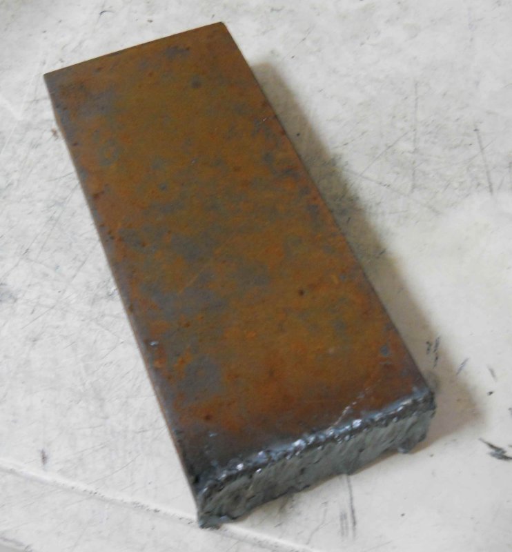
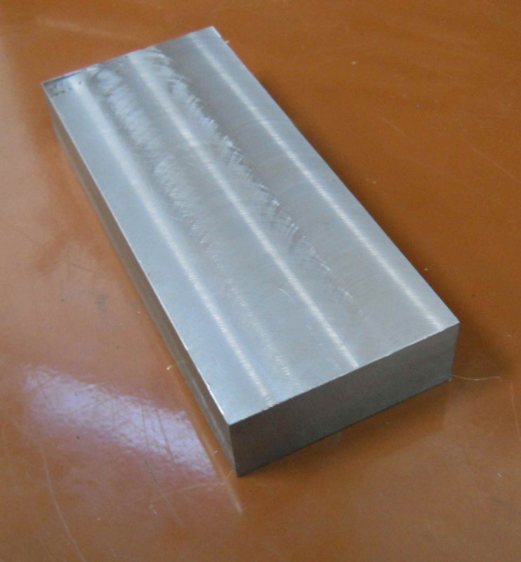
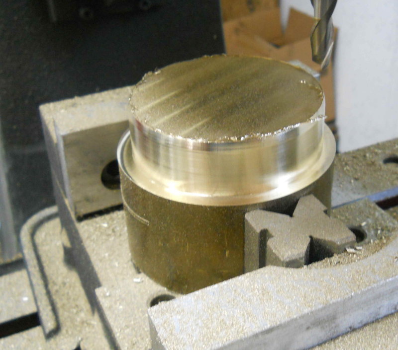
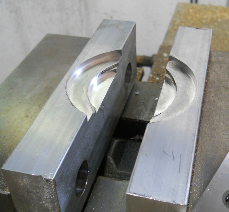
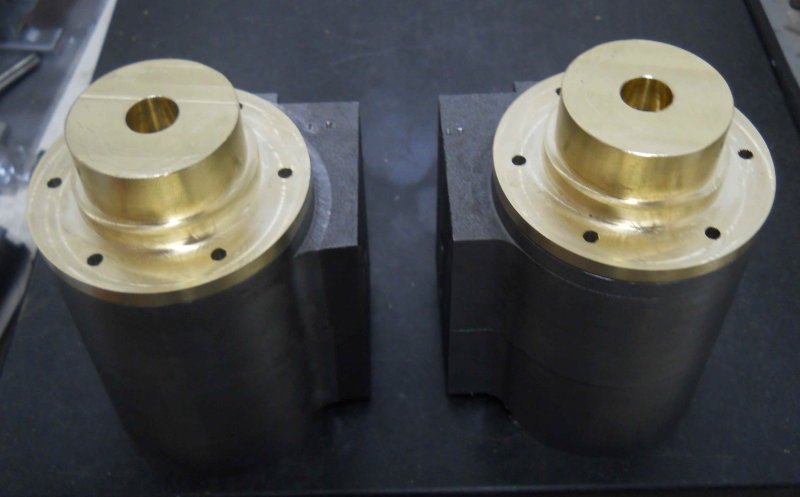
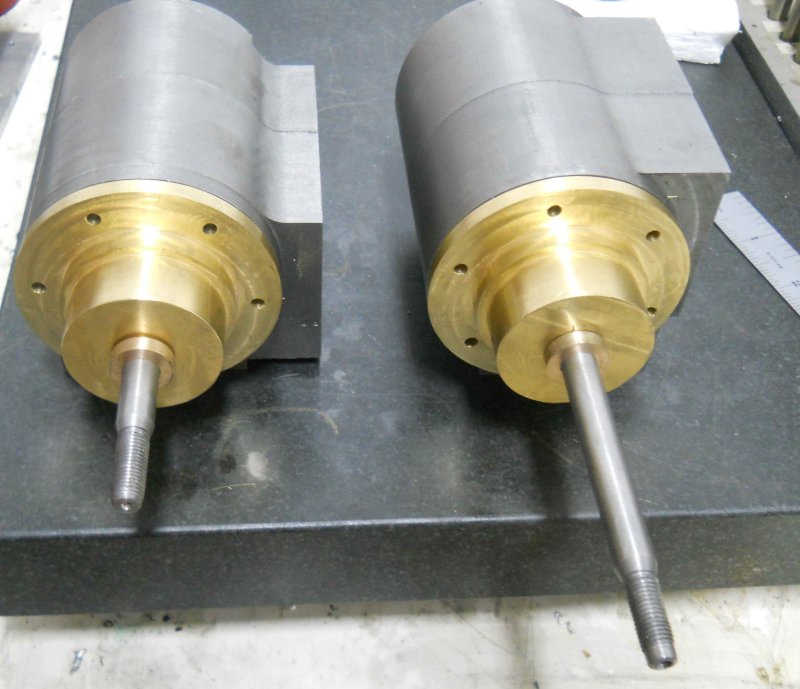
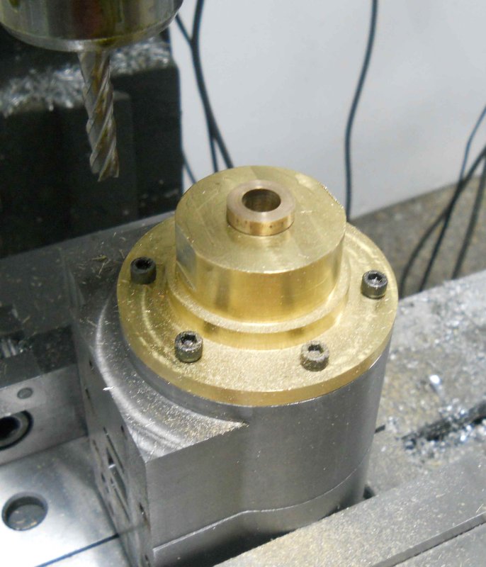
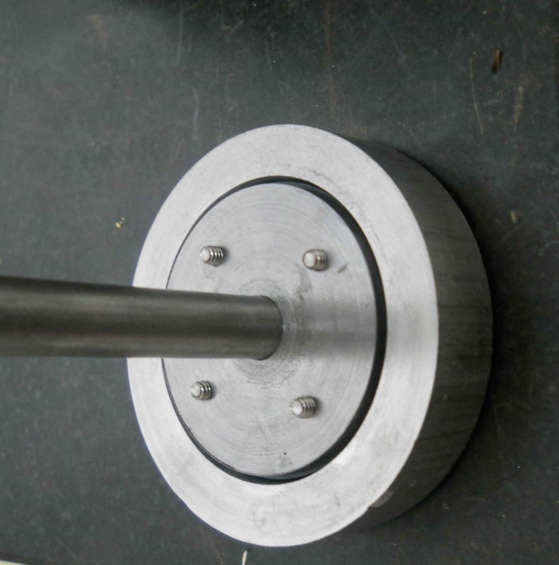
For a short shop session today, I made a start on the rear cylinder heads. These start as a 4" diameter drop of brass about 4" long that I bought at NAMES. I tried cutting it in two with the bandsaw, but couldn't get the blade to start straight, so another strategy was needed. After face milling both sides flat, I used the CNC mill to reduce the diameter to 3.5" for a length of 1". This meant that I could chuck it in the lathe.

large.jpg


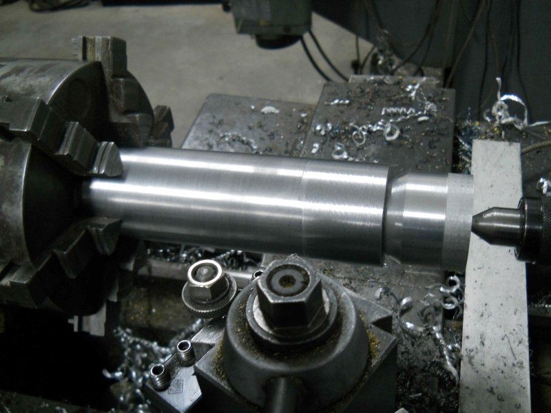
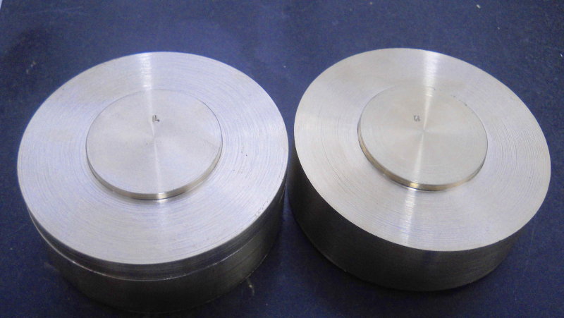
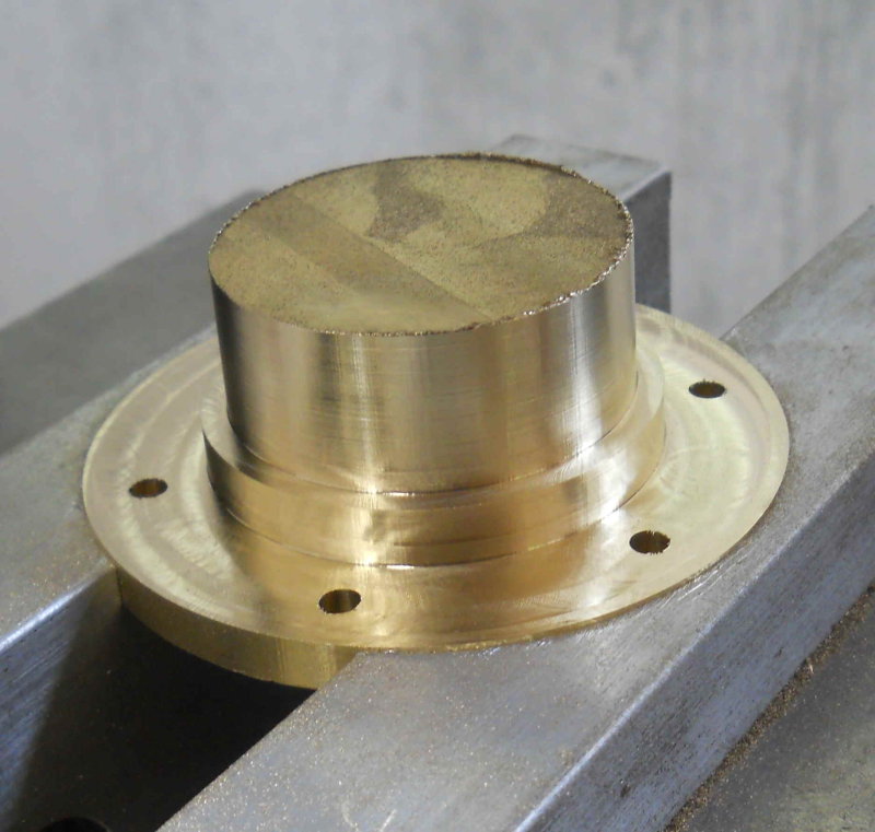
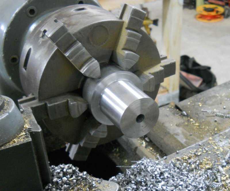
Now I could turn most of the rest down to 3.5", then face and turn the bore spigot for the first cylinder.

large.jpg


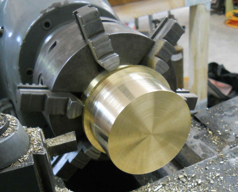
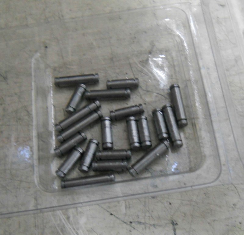
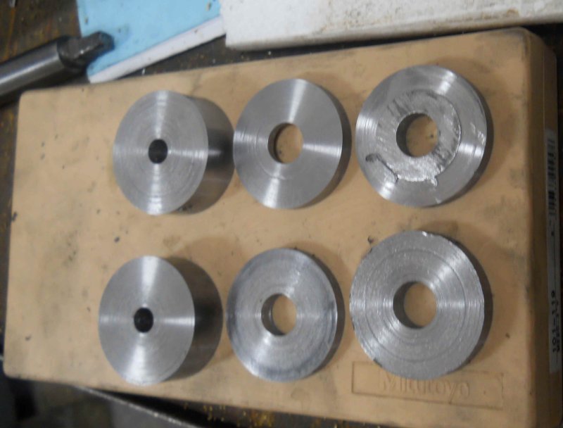
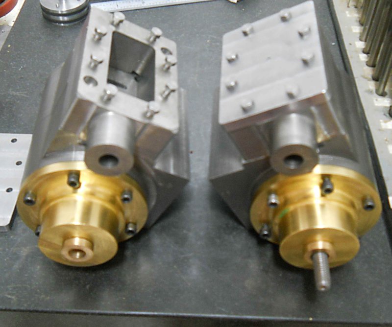
Then I needed to part off the first one. Using a 1/8" parting blade and the lathe in back gear at 200 rpm, I was able to get a pretty good cut. I started out with only 1/2" of blade exposed in the holder, and then successively extended it bit by bit. Once the outer slice started to wobble, I could just break it off by hand. Then I did machined the face and spigot for the second cylinder without needed to rechuck.

large.jpg


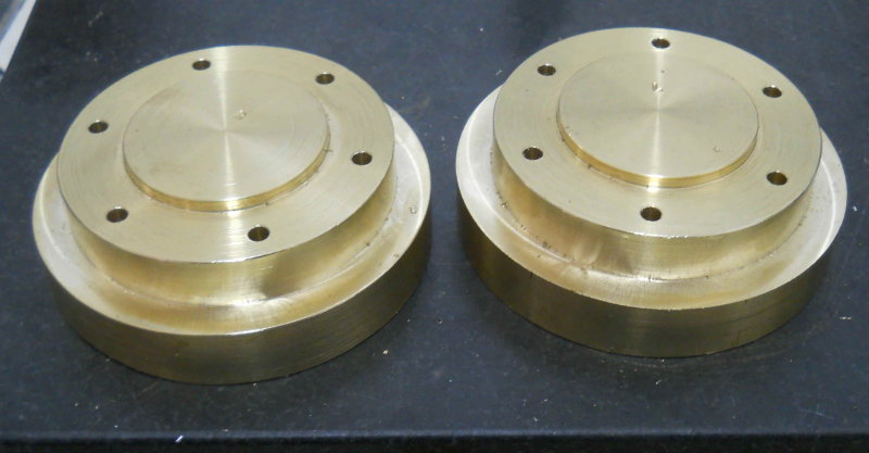
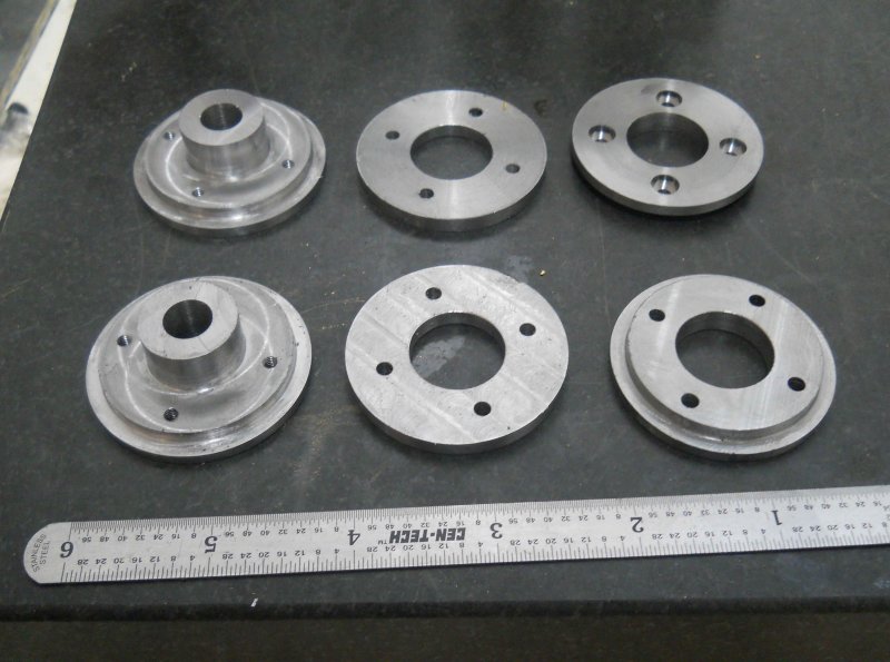
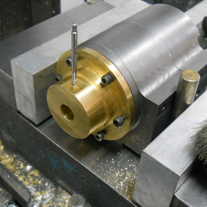
Since these are now 3.5" in diameter, I can use the same pockets in the soft jaws as for the front heads to continue machining.


The next ops on the rear heads were to drill the mounting holes and then mill the final flange diameter.

large.jpg


Now I needed new pockets on the soft jaws.

large.jpg


Now the two spigots on the rear side of the head could be milled.

large.jpg


Then the through hole was drilled and reamed .380, and the bushing pocket was milled: .507 diameter, .782 deep using a 3/8 endmill.

large.jpg


There are still some ops needed on these parts for mounting the crosshead guides, but that will wait until I know the piston will move properly. So the next tasks will be to machine the bushings to fit the pocket, and then make the pistons. I already have the rings, so once it's all together will be the moment of truth.
 
The past few shop sessions were for making the pistons, parts that seem pretty simple looking at the plans but which took me a lot of time to realize. I started with a piece of 2.5" diameter CI rod left over from a previous project. There was "just" enough there to make the 6 pieces needed for two pistons, so some rechucking at the lathe was necessary.

First I turned the diameter down to the 1.745" called for in the plans, then drilled and reamed through.

large.jpg


After much difficulty and breaking my 1/16" parting tool twice, I got the pieces roughed out.

large.jpg


Lots of milling, drilling, reaming, counterboring and tapping later, the result:

large.jpg


I loctited the large pieces to the piston rods, then assembled using 5-40 screws. Now I could chuck the rod in a collet on the lathe and take a small turning cut to true all the diameters.

large.jpg


Then I turned the bushings from phosphor bronze and did a quick assembly with the cylinders.

large.jpg


The good news is that both pistons slide smoothly within the cylinder bore, although neither the rings nor the screws for the heads are in place. I have tested that the rings do fit well in the bore. However, the piston body needs enough clearance to account for expansion when running. This is needed since the piston will expand faster than the cylinder when steam is introduced. Kozo's plans call for .005" difference in the piston and bore diameters; based on the design however, I think the clearance can be a bit larger than that without harm.

While the green loctite 620 should be sufficient to fix the piston on its rod, I will also add the pin that Kozo specifies for extra security.
 
Some small but tedious progress today. Using the cylinders as jigs to hold the heads, I milled the flats where the crosshead guides will attach.

large.jpg


I think this is a better/quicker method than that used by Kozo for the smaller version. Then I drilled and tapped the 5-40 holes for attaching the guides, as well as the hole for the set screw that retains the bushing.

large.jpg


Finally, used a piece of aluminum round to turn the "piston insertion tool" show on fig. 5-8 on pg. 225. This jig has a tapered bore that compresses the rings as the piston is pushed through into the cylinder. It's almost impossible to insert the piston and rings into the cylinder without this (although I tried hard).

large.jpg


Following photo is a test fit of the steam chest/cylinder/cover using the model scale screws from AMS. I plan to leave these exposed and not fabricate the outer covers. The same type of screw will be used for the heads.

large.jpg


Back at it after some family vacation time.

I finished the machining of all the spring hangers from pg. 210.

large.jpg


I made this harder than it needed to be. If I can remember not to try to cut slots with a 4-flute endmill and not to reply on cheap Chinese 1/8" carbide endmills for anything, things might go better in the future.

Still to do is round the edges that go through the spring slots, heat and twist two of the hangers 90 degrees, and turn all of the pins that hold it all together.

I also need to remake the spring bands (pg. 209). I find that with the springs cambered they don't fit through the opening. Rather than as drawn, I'm going to make the tops open with a cap.
 
Some excellent looking parts and good progress. Its got me itching to get started on a Kozo Shay.
 
This is a major project, I have read only to the end of page 5 to date so if it’s not been asked before, have you a rough idea how long it takes to complete something like this.
Not that I am thinking of following in your footsteps, it’s a just a little beyond my skill level, like about 3000 light years or so. Will be following to the finish.

Les :bow:
 
I started this right after Thanksgiving last year. I have a goal of getting "chassis on air" state by the end of this year, and having a steamable locomotive in another year. Once I get the springing sorted out, I need mainly to finish the valve gear and crossheads to be able to test on air.

I am not making the boiler and smokebox myself. Being retired, I expect to be able to spend an average of 10 hours or more per week of shop time. Having a CNC mill helps with parts such as those in the last picture. Without a full size mill and lathe it wouldn't be possible to build it at this scale. I also have the resources of some very experienced builders at my club to draw upon for advice.

I have not decided whether I will make the A3-style slantback tender or buy a fiberglass tender tank. In either case I plan to purchase the tender trucks from Tom Bee with air brakes. I also plan to install an injector in addition to the axle pump, and thus may skip the tender hand pump. I will also purchase the couplers, ball valves, and possibly the handrail stand castings.

I will also decide at some point whether to purchase a pre-made lubricator and/or whistle. I will likely install automatic cylinder cocks at first, then fabricate the finicky manual parts at the end.

My current estimate is that I will spend ~$4-5K on materials, with more than half going to pay for the boiler and smokebox. The 3/4" scale would be much cheaper to build, although probably not much faster.
 
Current boiler prices for say a Gene Allen 1-1/2" Mogul run around $3300-$3500 from one of the boiler shops. Just a point of reference.

Mike
 
With the hangers machined, I now needed only the gibs (spring retainers) to make before trial fitting. While the gibs are pretty simple, I find making them a bit tedious as they are small.

large.jpg


Both the gibs and hangers needed to have rounded edges to fit through the slots milled in the spring bands. It would have been better to have made the slots longer than per plan, as that way the rounding wouldn't be necessary. As it was, I held the parts with a vise-grip and worked on them via the grinding wheel. Not pretty, but it works. The hangers that attach to the equalizer beam needed to be twisted 90 degrees. I clamped them in the bench vise, heated with a MAPP gas torch, and twisted with a large wrench.

Since I haven't made any of the pins that hold it all together, I just did a trial fit using screws.

large.jpg


I haven't put any camber into the spring leafs as yet. With just the frame weight, the flat springs support the axles with about 1/4" of up travel remaining. With the boiler/water and everything else there's about another 100 pounds left to support, so I need to put that amount of weight on and add spring camber to suit. The ideal height should have the cylinder centerline level with the axle centers. The spring bands won't get tops until I know how much camber I need.
 
Oh happy me. Very glad to see this thread again.
I have the book. I have the dream.
I need more...but this thread helps a lot.
 
Today was my first experience with e-clips, which Kozo uses extensively to retain pins. A majority of the pins used in the spring and brake rigging are 5/32" diameter. Unfortunately my 5C collet set is by 16ths, so I started with the few pins in the spring setup that are 3/16". The groove for the clips is spec'ed at .029 wide; I had a grooving tool that I ground for cutting cylinder fins on the Liney Halo, and it turns out that this works well. My "test" pin connects the brake equalizer with the cross member via two short hangers.

large.jpg


There are about 2 dozen 5/32 pins to do, and only the rubberflex chuck will hold that diameter. I'm going to order a 5/32 5C collet since I want to cut the groove close to the chuck face. In retrospect, I think almost all of these pins could be made with 3/16 drill rod.
 
Always a pleasure to see progress on this thread. :)

Brock
 
The order from Enco came yesterday so I now have a 5/32 5C collet for making the rest of the spring/brake pins. I also got two sheets of acrylic and a gallon of coolant, so I want to finish setting up the coolant pump and shield before using the CNC mill again. Once that's done, the next parts to be milled will be the crossheads.

Yesterday I visited the local steelyard and picked up this chuck of CRS (1x2.5x6) from which two crossheads will be milled together.

large.jpg


I milled off the torch slag with a roughing endmill, then cleaned up 5 sides with a face mill.

large.jpg
 
Buried under all that rust is a beautiful piece of metal!

Buried under all that metal is the part you want to make ;D

- Ryan
 
Doing some "experiments" with a length of DOM tube that might work out as the smokestack.

I don't have a steady rest for the lathe, nor a bull live center, so this is my substitute. I took a piece of 2" aluminun, turned a 60-degree taper one end and center drilled the other. So it supports the tube for external turning.

I don't know if I can turn the internal taper with the end unsupported, however.

large.jpg


In any case, the smokestack won't be needed for quite some time.
 
Over the weekend I finished up all the e-clip pins that hold the spring hangers and brake levers together:

large.jpg


large.jpg


14 pins for springs and 20 for brakes.

There are a number of similar ones still to do for the valve and reverse gear.
 
We had workers all morning tearing up half the kitchen floor wood (refrigerator leaked), so only a short time in the shop today.

I fit together the bits of the brake system that use pins and e-clips to test for fit (pg. 213 in Kozo book). I need to remake one pin that's a bit short.

large.jpg


The two links that connect to the break beam are probably a bit too tight fitting, even with some grinding and filing. I need to get the return springs to see if they will be strong enough or whether I need to make the fit looser. I was able to verify that the brake beam length is good so that I can machine the e-clip grooves in it next session.
 
Back
Top