
You are using an out of date browser. It may not display this or other websites correctly.
You should upgrade or use an alternative browser.
You should upgrade or use an alternative browser.
Kozo A3 in 1.5" scale
- Thread starter kvom
- Start date


Help Support Home Model Engine Machinist Forum:
This site may earn a commission from merchant affiliate
links, including eBay, Amazon, and others.
- Joined
- Jan 3, 2008
- Messages
- 2,085
- Reaction score
- 17
Kvom, I have been watching this one from the beginning and I admire you loco guys for undertaking such intricate projects. Its looking so good thus far and I definitely look forward to seeing more.
Bill
Bill
- Joined
- Jun 4, 2008
- Messages
- 3,285
- Reaction score
- 630
Matt and Bill (and any other silent witnesses), thanks for following along. So far nothing has been particularly difficult to make; it's just that the goal is a lot further away than for most models.
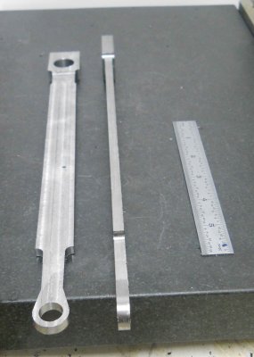
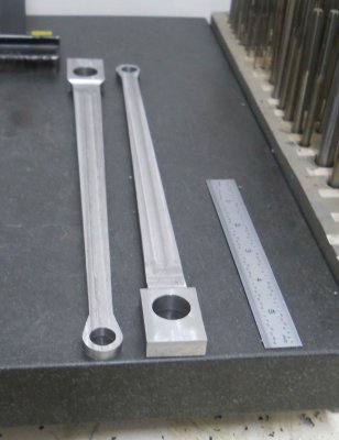
Yesterday I started on the return crank, a part that attaches to the rear crankpin and along with the motion of the crosshead creates the timing for the valve. After cutting and squaring pieces of 1.5x.5' steel and drilling the two holes, I mounted them in the CNC mill vise to mill the outer profile.
I used soft jaws here as I was milling quite close (leaving .10) and hate to mill my hard jaws. I also wanted to use the soft jaws for the last step.
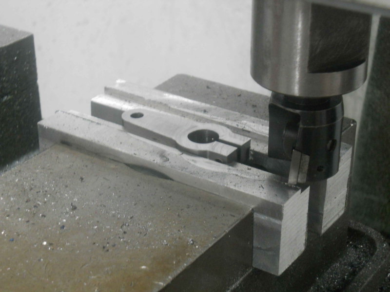
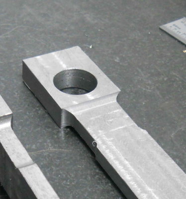
Now to the Bridgeport to mill the relief (needed to clear an e-clip for the attached part). The radius cut was done with a 1/4" ball end mill, taking lots of small cuts.
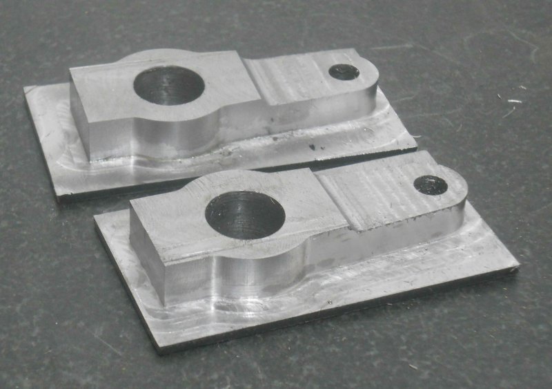
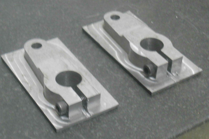
Next, I milled the clamping slots using a 1/8" endmill on the Bridgeport, taking only .015 DOC each pass and blowing chips with air all the while. Tedious, but the endmill survived. Per plan, the slot would be 1/16 but it doesn't matter in this case.
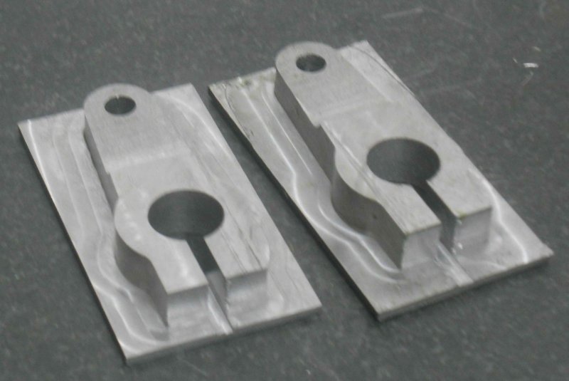
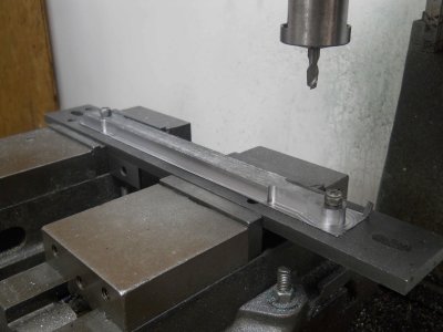
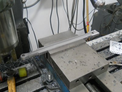
Next, I drilled and tapped the clamp screws using 8-32x1"
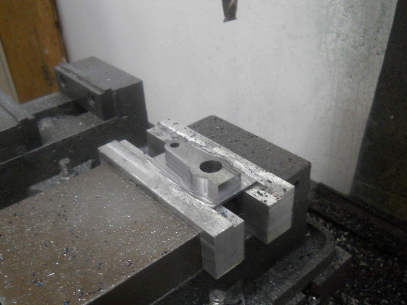
Now it remained only to remove the square backing that remains. Since the part is not suitable for regular cvise clamping, I milled a pocket in the CNC vise's softjaws, enabling the parts to be held securely. Then used the facemill.
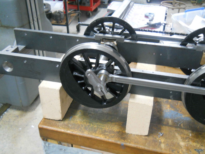
Mounted on the crank pin for a poser shot:
Yesterday I started on the return crank, a part that attaches to the rear crankpin and along with the motion of the crosshead creates the timing for the valve. After cutting and squaring pieces of 1.5x.5' steel and drilling the two holes, I mounted them in the CNC mill vise to mill the outer profile.
I used soft jaws here as I was milling quite close (leaving .10) and hate to mill my hard jaws. I also wanted to use the soft jaws for the last step.
Now to the Bridgeport to mill the relief (needed to clear an e-clip for the attached part). The radius cut was done with a 1/4" ball end mill, taking lots of small cuts.
Next, I milled the clamping slots using a 1/8" endmill on the Bridgeport, taking only .015 DOC each pass and blowing chips with air all the while. Tedious, but the endmill survived. Per plan, the slot would be 1/16 but it doesn't matter in this case.
Next, I drilled and tapped the clamp screws using 8-32x1"
Now it remained only to remove the square backing that remains. Since the part is not suitable for regular cvise clamping, I milled a pocket in the CNC vise's softjaws, enabling the parts to be held securely. Then used the facemill.
Mounted on the crank pin for a poser shot:
- Joined
- Jan 3, 2008
- Messages
- 2,085
- Reaction score
- 17
Kvom, still looking good and I love the "poser" shot too. Steam and IC engines are all fascinating but something about a loco coming to life is extra special! I noticed the coax indicator...you gotta love those...just wish I could find one in a smaller size for benchtop equipment. I also noticed in your profile that you are from Cumming GA. I grew up in Atlanta and as a kid we would spend most summer weekends in the north Georgia mountains camping and often came through your neck of the woods.
Looking forward to more as you progress.
Bill
Looking forward to more as you progress.
Bill
- Joined
- Jun 4, 2008
- Messages
- 3,285
- Reaction score
- 630
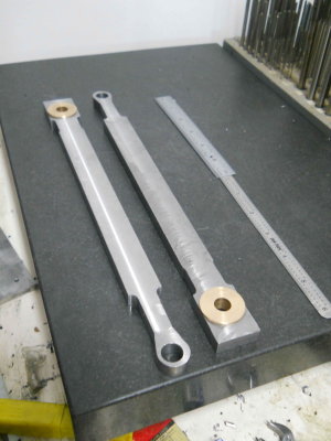
The past three days were spent making the main rods, with shop time interspersed with real life.
I had cut and faced the 1/2" CRS stock a while back, so the first tasks were to drill mounting holes in both the stock pieces and the jig plate, similar to the side rods. Then it was on to the CNC mill to make the outer profile.
Then it manual milling for all the rest. First, face mill to remove the bottom remainder.
I diverged from the plans a bit, as Kozo's dimensions result in a 1.4 degree included angle between the top and bottom of the shafts. Since I was going to use angle bars to finish the angles and have only integer angles, I redrew it to give a 2 degree shaft taper. In order to be able to mount the shafts in the milling vise, the CNC profile has the taper on both ends and leaves it square in the center.
The next operation was to drill/bore/ream the bearing holes, .75" and .5".
The next operation was to mill the shaft to a .25" thickness.
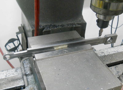
Next mill the side radii using a 1/4" ball end mill.
Next finish the first taper using a 1 degree angle bar for setup.
For the opposite side I needed a 2 degree bar.
Poser shot:
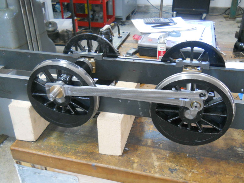
I had cut and faced the 1/2" CRS stock a while back, so the first tasks were to drill mounting holes in both the stock pieces and the jig plate, similar to the side rods. Then it was on to the CNC mill to make the outer profile.
Then it manual milling for all the rest. First, face mill to remove the bottom remainder.
I diverged from the plans a bit, as Kozo's dimensions result in a 1.4 degree included angle between the top and bottom of the shafts. Since I was going to use angle bars to finish the angles and have only integer angles, I redrew it to give a 2 degree shaft taper. In order to be able to mount the shafts in the milling vise, the CNC profile has the taper on both ends and leaves it square in the center.
The next operation was to drill/bore/ream the bearing holes, .75" and .5".
The next operation was to mill the shaft to a .25" thickness.
Next mill the side radii using a 1/4" ball end mill.
Next finish the first taper using a 1 degree angle bar for setup.
For the opposite side I needed a 2 degree bar.
Poser shot:
- Joined
- Jun 4, 2008
- Messages
- 3,285
- Reaction score
- 630
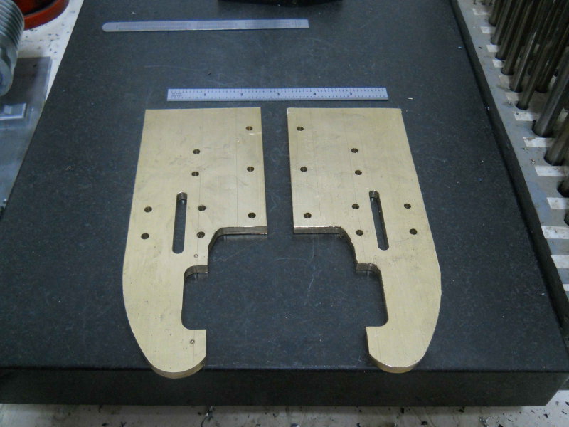
The past two shop sessions were spent making the main parts of the yokes. These psrts are attached to a tie plate and in turn the frame. In turn 3 brackets for the valve gear linkage plus the crosshead guides attach to each yoke, and the radius rod passes through the slot. I decided to make these from brass for a couple of reasons. First, I had a 6' length of 4x1/4" 360 brass, and second because some silver soldering is needed and I am more confident in soldering brass than steel.
The first operation on the mill was to drill all of the clearance holes for the 8-32 mounting screws. I also cut out one corner on the bandsaw which would otherwise be milled away. The screw holes provide mounts for an aluminum jig plate that I also drilled.
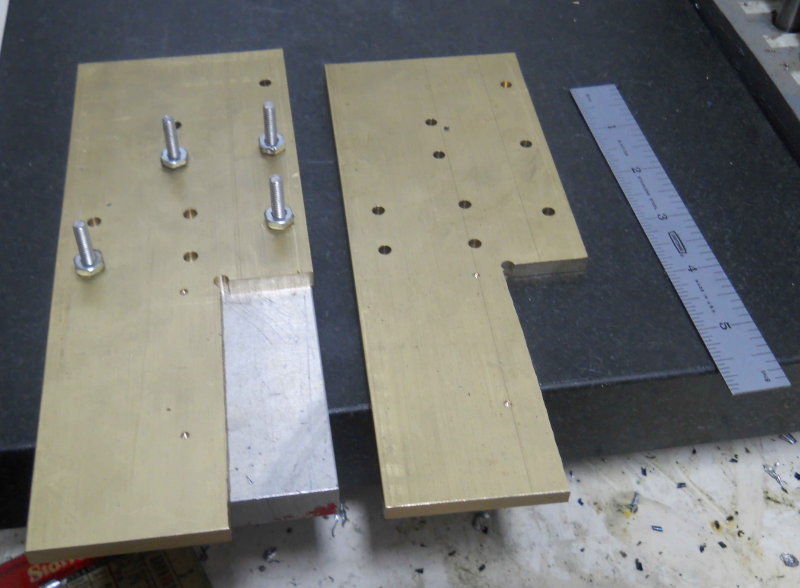
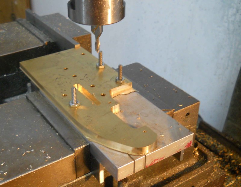
Now the CNC mill carved out the outer profile plus the slot:
After deburring, they're ready for soldering on a bar on the top, providing a support for the walk boards, and two cubes on the bottom that will be the attachment points for the crosshead guides.
The first operation on the mill was to drill all of the clearance holes for the 8-32 mounting screws. I also cut out one corner on the bandsaw which would otherwise be milled away. The screw holes provide mounts for an aluminum jig plate that I also drilled.
Now the CNC mill carved out the outer profile plus the slot:
After deburring, they're ready for soldering on a bar on the top, providing a support for the walk boards, and two cubes on the bottom that will be the attachment points for the crosshead guides.
Breathtaking it is. I sit here shaking my head and saying to myself, "self, you too could do that, it's easy, I tell you... easy." to which my usual reply is "yeah.... right" and then the wife says "what did you say".......... grumble, grumble, easy I told you. And of course she doesn't understand. ???
BC1
Jim
BC1
Jim
- Joined
- Jun 4, 2008
- Messages
- 3,285
- Reaction score
- 630
Most of the machined parts in this engine are not that hard. Kozo likes to put a lot of radii on parts that would work without them but wouldn't look as good. These yokes would be one of the harder parts to make manually as the two curves in the profile do not have centers that are easy to locate on the stock itself. His drawing, in fact, doesn't help much in that respect either, and I needed to use a CAD option to draw the circles. The smaller circle has a given radius and passes through two points. The larger has a given radius and is tangent to a line and the smaller circle. Of course, once the drawing is done that way the centers are defined.
Were I doing this manually, I would do them one of two ways:
1) rotary table
2) Print the drawing full scale, cut out the profile, and trace it on the stock. Milling and filing could give a perfectly acceptable result.
I think the hardest part about this project is the sheer number of parts to be made, and the possibility of losing interest as the project drags on. I've been told that the average time to completion of a builder's first loco is 9 years! My target is a chassis running on air by the end of this year, and under steam by the end of 2012.
- Joined
- Jun 4, 2008
- Messages
- 3,285
- Reaction score
- 630
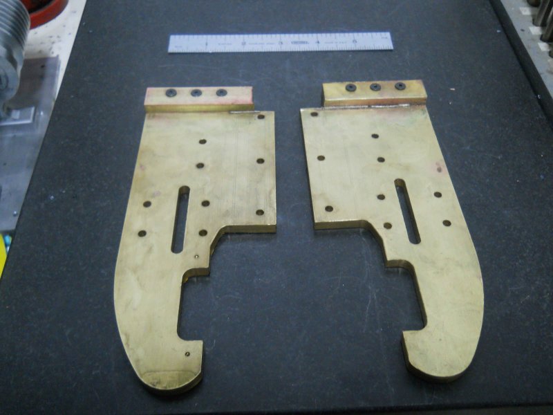
After a couple of days devoted to working on the Jeep, I finally got back to the shop to continue on the yokes. The plans call for a 1/4" thick piece to be silver-soldered to the top edge forming a platform to which the walkboards are screwed. Unfortunately, when I tried to SS them, I was not able to get the pieces hot enough for the solder to melt. It seems that the brass just conducts the heat away too fast (I was using MAPP gas torch). So my alternative was to screw the piece to the yoke with 6-32 screws, which will be loctited. Kozo has the top mounting screws tapped into the soldered joint, but with my screw attachment I don't like that idea. So I plan to mill two holes in the joint and loctite drill rod pieces containing threaded holes instead.
On another front, I ordered the cylinder castings from Friend's Models, and they arrived yesterday.
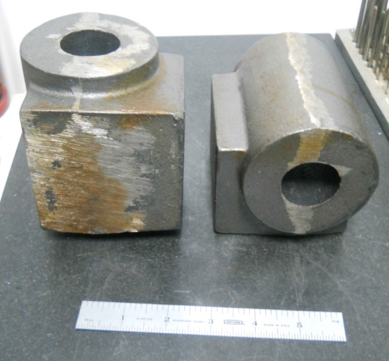
Each chunk of cast iron weighs around 12 pounds! I redrew Kozo's plans in CAD to scale up all the measurements, and it seems that there is plenty of extra material in all dimensions. I've got a decent idea of a machining plan, but want to get it all written down and reviewed before cutting any metal.
On another front, I ordered the cylinder castings from Friend's Models, and they arrived yesterday.
Each chunk of cast iron weighs around 12 pounds! I redrew Kozo's plans in CAD to scale up all the measurements, and it seems that there is plenty of extra material in all dimensions. I've got a decent idea of a machining plan, but want to get it all written down and reviewed before cutting any metal.
- Joined
- Jun 4, 2008
- Messages
- 3,285
- Reaction score
- 630
Made a start on one of the cylinder castings today. It seems likely that these castings were made originally for a larger engine, as the dimensions are quite "excessive" in every direction. That's not a problem, but there's that much more material to machine away and thus more time. I first machined the steam chest and frame faces flat and square to each other in order for to of the jaws on the lathe chuck to have full contact. I then machined one of the ends flat in order to set square to the face of the chuck.
My largest boring bar can only go 4.25" deep, and the casting was about 4.6" in length. So it was necessary to mill both ends down until the length was about 4.1". The final length is 3-7/8, so there's a lot to be removed.
Then it was time to mount in the 4-jaw and center on the bore in the casting. It's not necessary to be to super-exact as the cast bore is somewhat irregular and there's lots of material available to adjust to the centerline once bored. I got it aligned to within 1/8" all around.
Luckily my chuck has a 2" center hole, so I could bore out to the target 1.75" diameter without worrying about boring into the chuck body. After multiple slow passes I crept up to the target diameter.
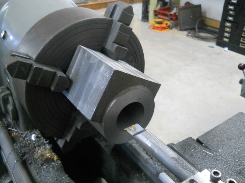
The casting is quite unbalanced, so I needed to keep the RPMs down to about 350 to keep the lathe from shaking. Once bored, I turned outer round surface down to it's target diameter, then faced .25" deep to square the sides of the faces. This is an interrupted cut so I took it quite slow.
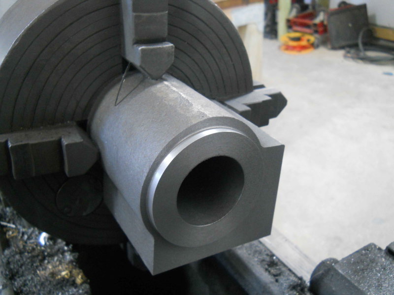
Once I removed the casting from the chuck, I stamped the face to identify it as the rear. Since it is as close to square to the bore as possible with the lathe, mounting the rear cover and piston opening there will be preferred.
That's as far as I got today. There's lots of machining to do on these, so it could take a while.
My largest boring bar can only go 4.25" deep, and the casting was about 4.6" in length. So it was necessary to mill both ends down until the length was about 4.1". The final length is 3-7/8, so there's a lot to be removed.
Then it was time to mount in the 4-jaw and center on the bore in the casting. It's not necessary to be to super-exact as the cast bore is somewhat irregular and there's lots of material available to adjust to the centerline once bored. I got it aligned to within 1/8" all around.
Luckily my chuck has a 2" center hole, so I could bore out to the target 1.75" diameter without worrying about boring into the chuck body. After multiple slow passes I crept up to the target diameter.
The casting is quite unbalanced, so I needed to keep the RPMs down to about 350 to keep the lathe from shaking. Once bored, I turned outer round surface down to it's target diameter, then faced .25" deep to square the sides of the faces. This is an interrupted cut so I took it quite slow.
Once I removed the casting from the chuck, I stamped the face to identify it as the rear. Since it is as close to square to the bore as possible with the lathe, mounting the rear cover and piston opening there will be preferred.
That's as far as I got today. There's lots of machining to do on these, so it could take a while.
- Joined
- Jun 4, 2008
- Messages
- 3,285
- Reaction score
- 630
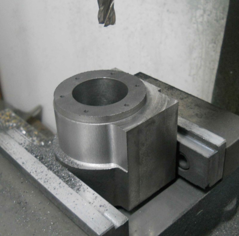
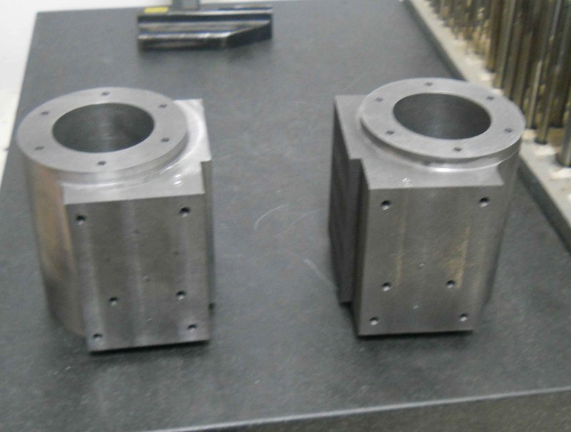
Today I continued to whittle away at the cylinder casting. First, I machined the front face to bring the piece to the overall final length, then face milled the steam and frame faces down. I left the frame face .025" higher to provide for possible fitment later.
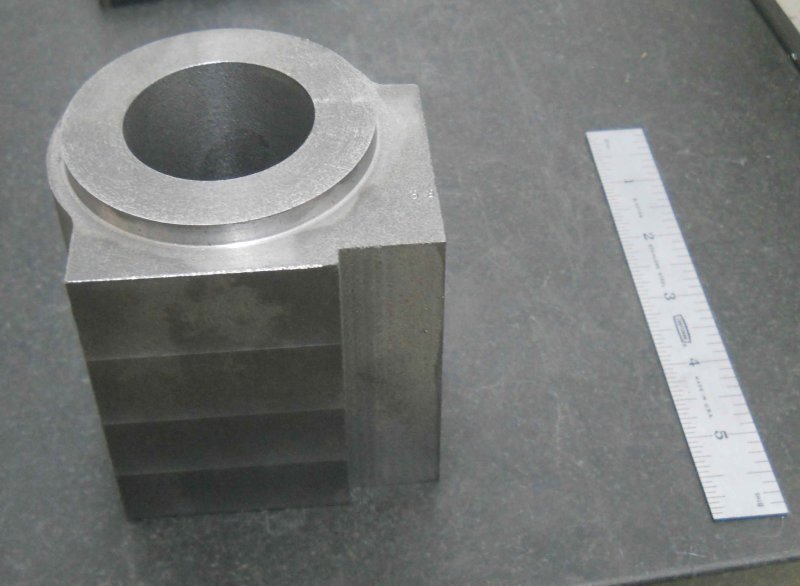
Next I mounted on the CNC mill with the front facing up and used the coax indicator to center on the bore. Then milled to yield this:
The final work of the day was drilling the mounting holes for the front cover.
I still need to figure how to mill the outer curved profile. Kozo's lathe method would be impractical given the amount of CI still to be removed.
Sparticusrye
Active Member
- Joined
- Mar 28, 2011
- Messages
- 43
- Reaction score
- 4
If your going to be using the mill to take the outside down to size then I would recommend making an arbor to go through the bore with a slight taper or a two piece arbor that is threaded to clamp the piece. Then mount it in an indexing head with tailstock support and mill it down rotating a few degrees after each cut until its to size. I am sure there are other ways but that would be my choice.
James
James
- Joined
- Jun 4, 2008
- Messages
- 3,285
- Reaction score
- 630
That's one thought I had; I have a HV rotab, but no tailstock; it would likely work OK.
My current plan is to use the CNC mill mounted as in the photo above. I'll have to turn it over to do in two passes. I'll try it out leaving a large clearance to see how close I can get between the two. If the edges meet cleanly then I'll take it to final dimension.
My current plan is to use the CNC mill mounted as in the photo above. I'll have to turn it over to do in two passes. I'll try it out leaving a large clearance to see how close I can get between the two. If the edges meet cleanly then I'll take it to final dimension.
Sparticusrye
Active Member
- Joined
- Mar 28, 2011
- Messages
- 43
- Reaction score
- 4
As long as you take your time and double check everything you should be able to get it close. Then, with a little filing and sanding, you would be able to remove any line caused by small missalignments.
I'll be following your progress as I am planning on starting a Kozo project sometime in the, hopefully, near future. I'm just not sure if I want to build the A3 or a Shay.
James
I'll be following your progress as I am planning on starting a Kozo project sometime in the, hopefully, near future. I'm just not sure if I want to build the A3 or a Shay.
James
- Joined
- Jun 4, 2008
- Messages
- 3,285
- Reaction score
- 630
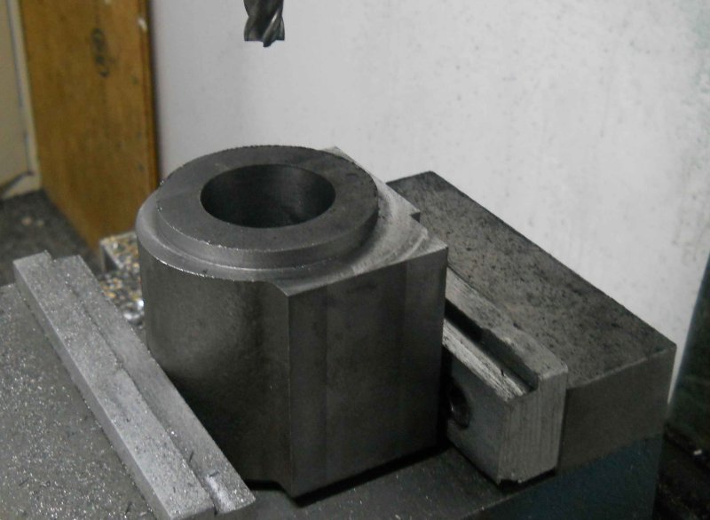
I decided to CNC the outer profile, and up to the end it went well. The first step was a roughing pass leaving .05 " of material for the finish pass. Each pass needs to be done twice (with the profile mirrored) because of the total depth. Here's the end of the first roughing pass:
Then the first finish pass:
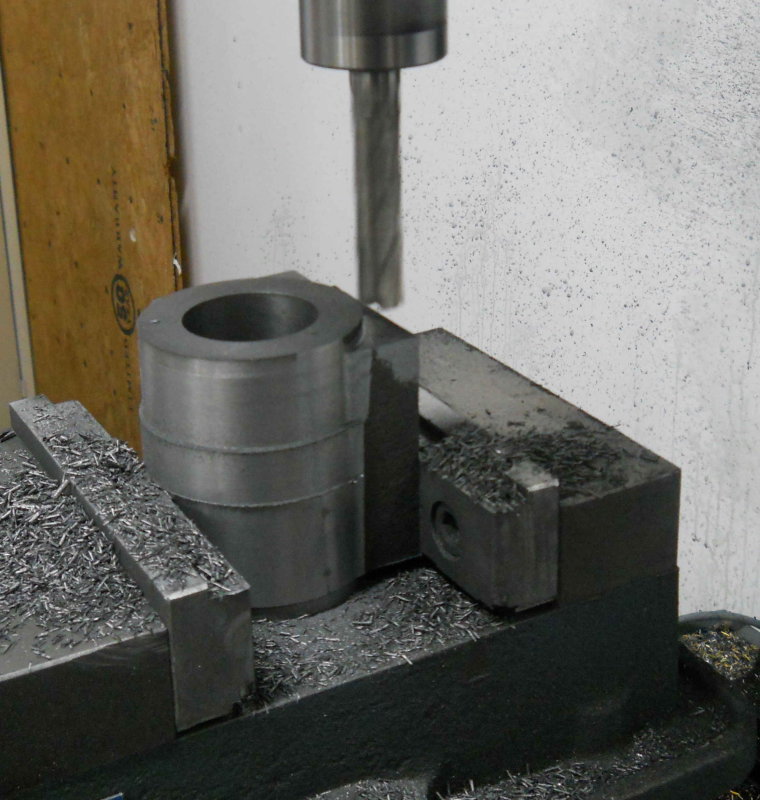
After that the setup was good for drilling the rear cover mouting holes.
Then on the final finish pass, the mill decided to have a mind of its own and cut into the face a bit before I could hit the stop.
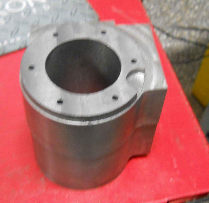
That blemish is not in a critical area and won't be seen with the front cover on as it will be next to the frame, so I'm going to continue on with it rather than throw away a $60 casting and a lot of shop time. Still pi$$ed about it though.
Having gone through the steps to this point, I have concluded that for #2 I can CNC the entire profile and save a lot of hand cranking on the Bridgeport. We'll see. And given that possibility, it will be just as easy to machine the cylinder from barstock as from the casting.
Then the first finish pass:
After that the setup was good for drilling the rear cover mouting holes.
Then on the final finish pass, the mill decided to have a mind of its own and cut into the face a bit before I could hit the stop.
That blemish is not in a critical area and won't be seen with the front cover on as it will be next to the frame, so I'm going to continue on with it rather than throw away a $60 casting and a lot of shop time. Still pi$$ed about it though.
Having gone through the steps to this point, I have concluded that for #2 I can CNC the entire profile and save a lot of hand cranking on the Bridgeport. We'll see. And given that possibility, it will be just as easy to machine the cylinder from barstock as from the casting.
imagineering
Well-Known Member
- Joined
- Dec 6, 2010
- Messages
- 96
- Reaction score
- 14
kvom said:
A good photo to post here;
http://www.homemodelenginemachinist.com/index.php?topic=14032.msg144465#msg144465
.
- Joined
- Jun 4, 2008
- Messages
- 3,285
- Reaction score
- 630
I weighed the machined cylinder at about 5 pounds, compared with 12 when I started. So there's 7 pounds of CI dust lying about the shop somewhere, and another 7 to go.
- Joined
- Jun 4, 2008
- Messages
- 3,285
- Reaction score
- 630
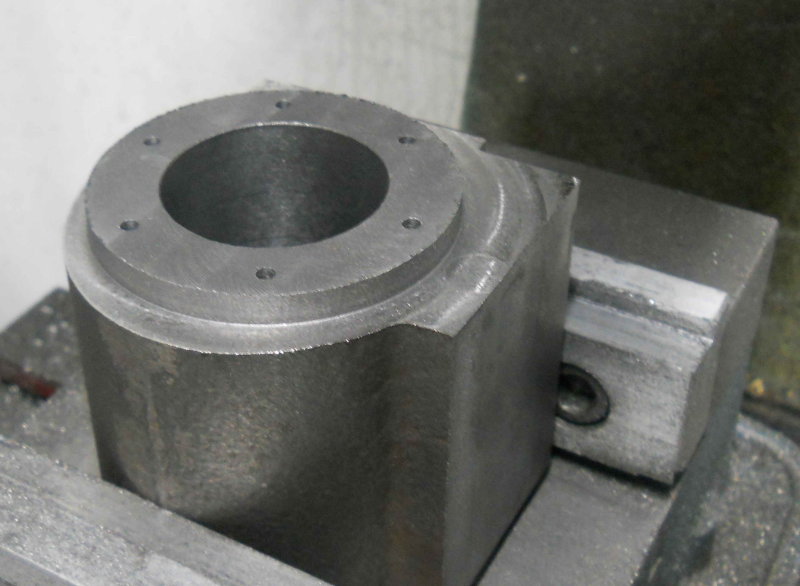
Some progress over the past few days since the last post. I bored/turned/milled the left hand cylinder out of its casting, and drilled the holes for the cylinder heads, so it was at the same stage of completion as the right hand. The next stage was drilling the mounting holes on the frame sides. Here my X zero is the center of the bore, the Y zero is midway between the ends. Here's how I set it up:
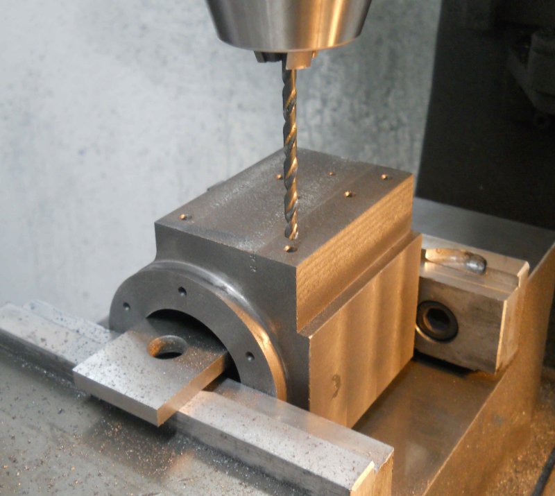
The parallel sits on the top of the vise jaws while the cylinder sits gently on the parallel. A square was used against the steam chest face to square the Z axis. Now an edge finder on either side of the parallel allows the centerline to be found. The hole pattern center is offset from the centerline to the outside, and the tee mounting holes are towards the front. Rather than mirroring the drawing and regenerating the g-code, I used the scale feature of mach3 to mirror the X axis. Thus I could use the same program for both cylinders. That's the first time I've used that feature. The holes for the steam admission and exhaust will be done manually on the Bridgeport. I center drilled to mark the locations.
Now the remaining milling is the steam ports and passages, something that can be a bit nerve-wracking, since a screwup is unlikely to be fixable. I decided to defer that task to a future date. In the meantime, I spent this morning making the steam chest covers on the CNC mill. These would be pretty easy manually, and probably as fast for one, but I wanted to have the rounded corners as Kozo specifies. The first cover tool a couple of hours total getting everything set up and checked out before cutting metal; the second took 30 minutes. I drilled the holes and then milled the profile .26" deep in some .50 CRS, then face milled the bottom on the Bridgeport. The profile was milled .02 oversize. I plan to do a finish pass with the steam chest, cover, and cylinder screwed together so that all have the same.
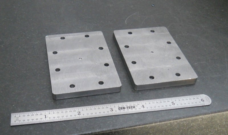
One of our club members suggests an extra pair of mounting holes between the steam chest and the cylinder using countersunk screws. These would allow the cover to be removed without the steam chest itself moving. This sounds like a good idea. I'll wait to finish the cylinders as drawn before figuring out a cood place for these holes.
The parallel sits on the top of the vise jaws while the cylinder sits gently on the parallel. A square was used against the steam chest face to square the Z axis. Now an edge finder on either side of the parallel allows the centerline to be found. The hole pattern center is offset from the centerline to the outside, and the tee mounting holes are towards the front. Rather than mirroring the drawing and regenerating the g-code, I used the scale feature of mach3 to mirror the X axis. Thus I could use the same program for both cylinders. That's the first time I've used that feature. The holes for the steam admission and exhaust will be done manually on the Bridgeport. I center drilled to mark the locations.
Now the remaining milling is the steam ports and passages, something that can be a bit nerve-wracking, since a screwup is unlikely to be fixable. I decided to defer that task to a future date. In the meantime, I spent this morning making the steam chest covers on the CNC mill. These would be pretty easy manually, and probably as fast for one, but I wanted to have the rounded corners as Kozo specifies. The first cover tool a couple of hours total getting everything set up and checked out before cutting metal; the second took 30 minutes. I drilled the holes and then milled the profile .26" deep in some .50 CRS, then face milled the bottom on the Bridgeport. The profile was milled .02 oversize. I plan to do a finish pass with the steam chest, cover, and cylinder screwed together so that all have the same.
One of our club members suggests an extra pair of mounting holes between the steam chest and the cylinder using countersunk screws. These would allow the cover to be removed without the steam chest itself moving. This sounds like a good idea. I'll wait to finish the cylinders as drawn before figuring out a cood place for these holes.
Similar threads
- Replies
- 111
- Views
- 21K
- Replies
- 11
- Views
- 6K