
You are using an out of date browser. It may not display this or other websites correctly.
You should upgrade or use an alternative browser.
You should upgrade or use an alternative browser.
Kozo A3 in 1.5" scale
- Thread starter kvom
- Start date


Help Support Home Model Engine Machinist Forum:
This site may earn a commission from merchant affiliate
links, including eBay, Amazon, and others.
- Joined
- Jun 4, 2008
- Messages
- 3,285
- Reaction score
- 630
doubletop said:Before you remove it all, don't you need a bit of side play so it will go around the bends in the track?
Pete
Yes. If everything matched the plans exactly there would be about .04" of sideplay, so I've a bit more. I've been told that having more is fine within reason.
zeeprogrammer
Well-Known Member
- Joined
- Mar 14, 2009
- Messages
- 3,362
- Reaction score
- 13
I'm also looking forward to the next installment.
Looks great kvom. I bet it feels great too.
Looks great kvom. I bet it feels great too.
- Joined
- Jun 4, 2008
- Messages
- 3,285
- Reaction score
- 630
I ordered paint and prep (POR15, degreaser, etcher, top coat) for painting the drivers prior to quartering. That should arrive Monday.
In the meantime I decided to skip a page and mill some aluminum, taking a break from the steel. Having scored a block of 3x3" 6061 from the school scrap bin, I started on the headlight. After making quite a lot of chips, I had the basic oblong stock milled to dimension.
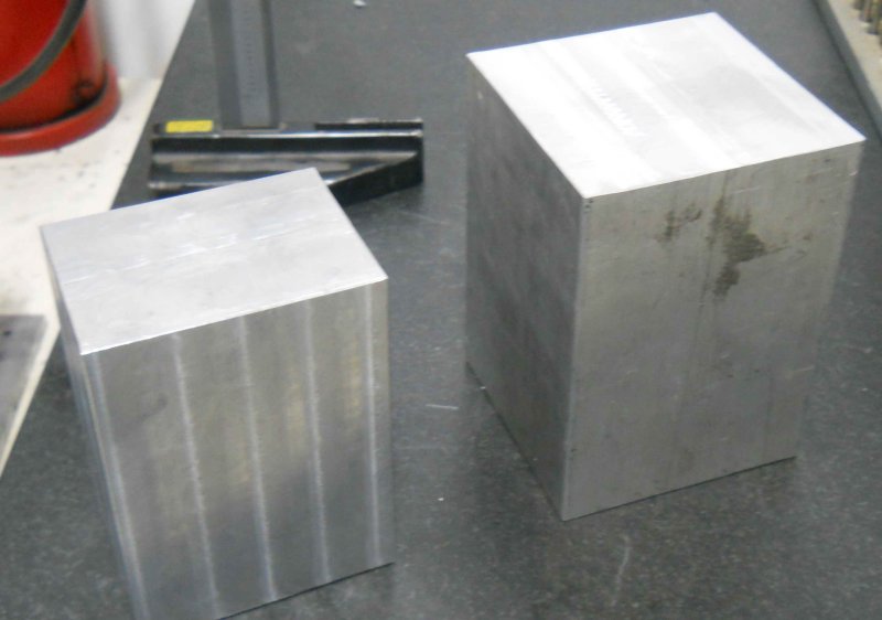
The rest was just cutting out the chimmney and the angles. My CAD program calculated the angles to several decimal places, but as I have only integer angle blocks I just rounded up. It still came out pretty decent.
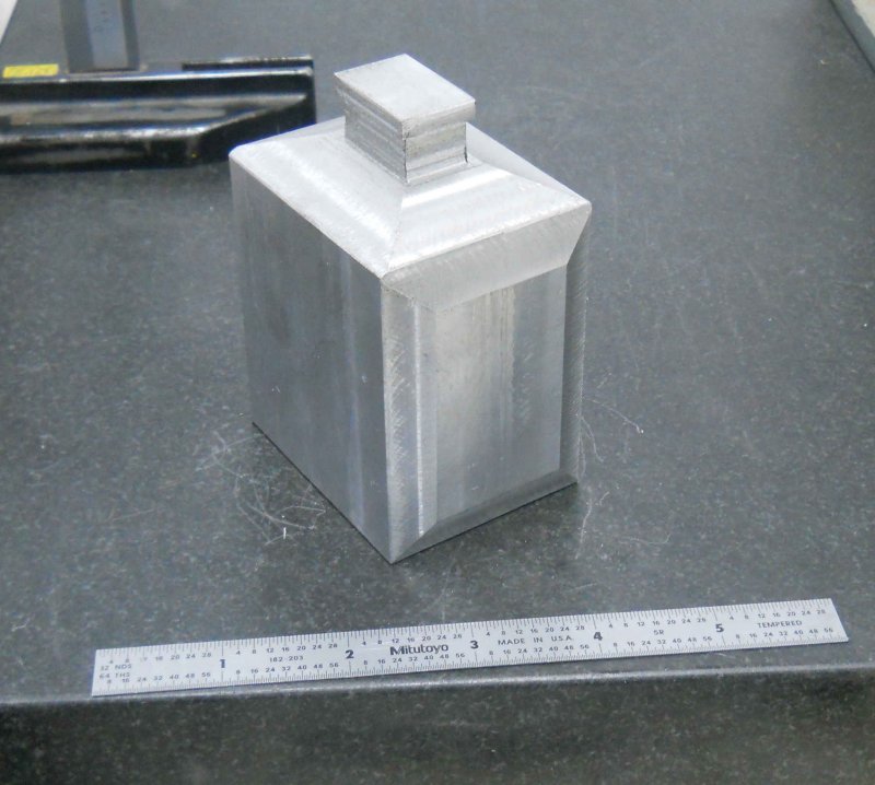
The next step is to bore out the cavity for a reflector and lamp, but that will wait until I acquire one and get its measurements.
In the meantime I decided to skip a page and mill some aluminum, taking a break from the steel. Having scored a block of 3x3" 6061 from the school scrap bin, I started on the headlight. After making quite a lot of chips, I had the basic oblong stock milled to dimension.
The rest was just cutting out the chimmney and the angles. My CAD program calculated the angles to several decimal places, but as I have only integer angle blocks I just rounded up. It still came out pretty decent.
The next step is to bore out the cavity for a reflector and lamp, but that will wait until I acquire one and get its measurements.
- Joined
- Jun 4, 2008
- Messages
- 3,285
- Reaction score
- 630
Yesterday's "work" was lots of filing of the spring bands trying to get the leaves to fit. Seems I milled the openings a little too small. I think that in retrospect making the opening about .03 (half a leaf) deeper might have been a good plan. All four now fit pretty snuggly, but some more filing may be called for on final assembly/
Today I made the first of 4 center bolts that screw into the spring band and pass through the center of the leaves to keep them all in place. I started with .5" 303 SS and got this:
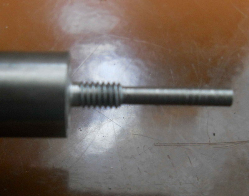
Then the same 5C collet was moved to the hex collet block on the mill to form the hex bolt head. I went with the 7/16 wrench size, although 3/8 might have been better.
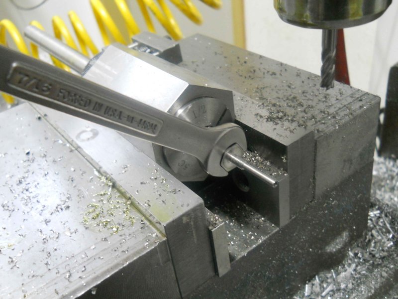
After parting, I tried using it to assembled one spring pack and band. Getting it all lined up with such a tight fit in the band was a problem, and when the springs are cambered it will be even tighter. So more filing may be in order soon.
So now I need to make 3 more of the same.
Today I made the first of 4 center bolts that screw into the spring band and pass through the center of the leaves to keep them all in place. I started with .5" 303 SS and got this:
Then the same 5C collet was moved to the hex collet block on the mill to form the hex bolt head. I went with the 7/16 wrench size, although 3/8 might have been better.
After parting, I tried using it to assembled one spring pack and band. Getting it all lined up with such a tight fit in the band was a problem, and when the springs are cambered it will be even tighter. So more filing may be in order soon.
So now I need to make 3 more of the same.
- Joined
- Jun 4, 2008
- Messages
- 3,285
- Reaction score
- 630
I got my package from POR15 yesterday, so now I can attempt to do some painting. POR15 is a rust preventing/restoring coating that is used a lot in restoring cars and other rusty metal. Given that steam locomotives are around steam and water, I figured rest prevention wouldn't be amiss.
Using this stuff is a multi-stage process. Now a friend and experienced builder told me to just use Rustoleum from the rattle can, that option seems too easy. The first stage for POR15 is degreasing, and the kit contains a cleaner called 'Marine Clean'. I diluted 2 cups with water at 5-1, poured into a flat plastic kitchen storage box, and submerged the 4 drivers along with several other pieces of scrap metal of various types. I'll use these scraps as test pieces before applying any paint to the drivers.
After soaking a couple of hours, the metal needs to be removed from the bath, rinsed off, and then sprayed with a 'Metal Prep'. This liquid etches the surface slightly enabling the POR15 to attach firmly to the surface. The metal surfaces get a thin coating of zinc phosphate. The parts are then rinsed in clean water and dried thoroughly. Any water getting into the paint will ruin it. I plan to put all the parts in the oven for a while at 200F to ensure complete dryness.
Now we apply the paint while wearing latex gloves, as it attaches itself very firmly to the skin. My starter kit has 3 1-pint jars, enough in principle to do everything I'v finished thus far. I plan to paint only the drivers at this time, once I'm satisfied that the scrap pieces look good. In principle POR15 gives a smooth, thin coating without brush marks when applied with a brush, so I'll see how that goes.
The final step is a top coat of paint, as POR15 deteriorates from UV if exposed to sunlight. My kit has 3 pints of a semi-gloss black that is supposed to adhere very well to POR15. if the results are as advertised, the resulting finish will be rustproof and extremely hard and scratch-resistant. I'll post pictures of my resuts later on.
- Joined
- Mar 3, 2008
- Messages
- 243
- Reaction score
- 20
I have used POR15 for restoring cars, It is a really good product. Mostly I used it where I did not want to cut out the metal. A good sandblasting, coat and dry. Just remember to put a piece of plastic wrap between the lid and can or you will never get it opened again. The stuff will weld the can shut  Also if you recoat, you should do it when the first coat is still tacky, you have to sand it if you let it completely harden.
IronHorse
Also if you recoat, you should do it when the first coat is still tacky, you have to sand it if you let it completely harden. IronHorse
- Joined
- Jun 4, 2008
- Messages
- 3,285
- Reaction score
- 630
Having a chest cold over the past week, plus band trips for the kids, I didn;t get much shop time lately. I did manage to paint the drivers with the POR15, and have been a bit disappointed with the results. The paint itself is not viscous, and a little goes a long way in coverage. I used a sponge "brush" to apply. On some flat test pieces the results were quite good, but with the drivers it dried a bit unevenly. I sanded the rims and other flat areas and painted on their black topcoat, but again the surface that resulted wasn't particularly good. I think spraying will work better once I get some equipment to do it. That said, I'll touch up the drivers again later.
Today I tool the drivers to school to quarter them. I know traditionalists will scorn my use of Loctite, but I feel confident that it will work just fine. Yesterday I used Loctite 620 to attach each axle to one driver, letting it cure overnight. I had previously made a pair of aluminum jigs out of round. One end was turned to .500" to fit the crank pin hole, and the other to .875" to match the axle diameter. Putting the axle and attached driver in a v-block on a surface plate, I turned the it so that the top of the axle and the top of the jig were level, using a height gauge as the reference. The axle is then clamped into position on the v-block
The crank pin hole is now horizontal with the axle hole to a quite good level of precision. The second driver has Loctite applied to the axle bore, and with the second jig in place was inserted onto the axle. On this side the jig and axle are aligned vertically with a machinist square, again with a good degree of precision.
The two crank pin holes are thus oriented at 90 degrees to each other (QED). The setup was allowed to cure for a couple of hours, although the Loctite would cure sufficiently to remove from the setup within 15-20 minutes.
To ensure proper spacing between the drivers, I had made a spacer from some aluminum rod that I faced to 7.125". This rod was placed between the backs of the drivers when placing the second driver onto the axle.
- Joined
- Jun 4, 2008
- Messages
- 3,285
- Reaction score
- 630
Still fighting the cold, but the past few days resulted in two partially finished parts. I bought some more 1/2" CRS, so decided to attempt the eccentric strap for water pump. This has three separate parts, including the rod. The first half of the strap was profiled on the CNC mill.
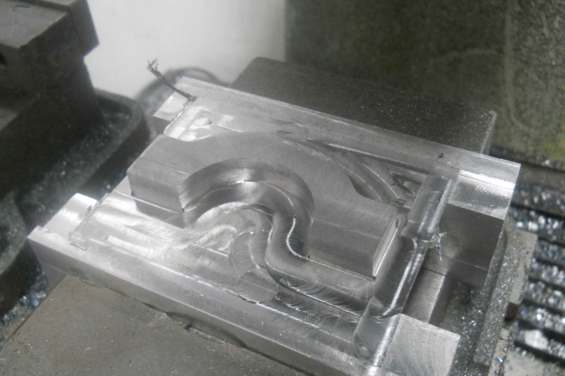
Then the part is chucked upside down on the Bridgeport, and the support material whittled away with a face mill. I rather like this method of "fixturing" as it results in a good finish on both sides.
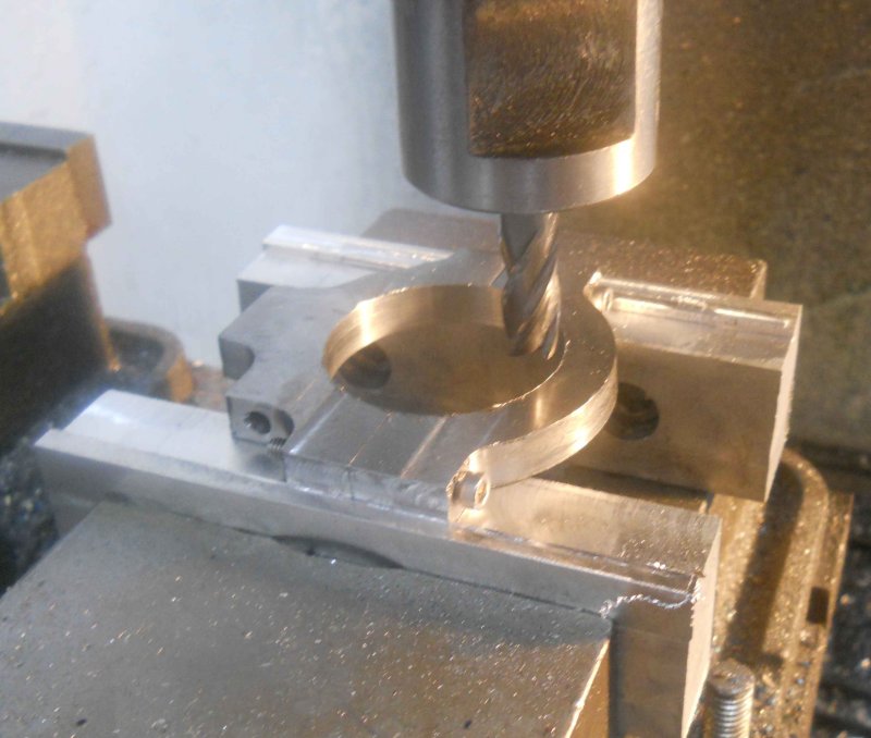
The other half of th strap was machined the same way. Then with drilling and tapping, the two halves can be screwed together. I then faced both sides of the combined strap with the face mill to get the sides flat and parallel before going back to the CNC mill.
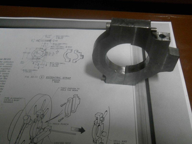
The center bore had been left a good 1/8" small when milling the halves, and now with them together the finish diameter can be milled.
Now the fit to the eccentric:
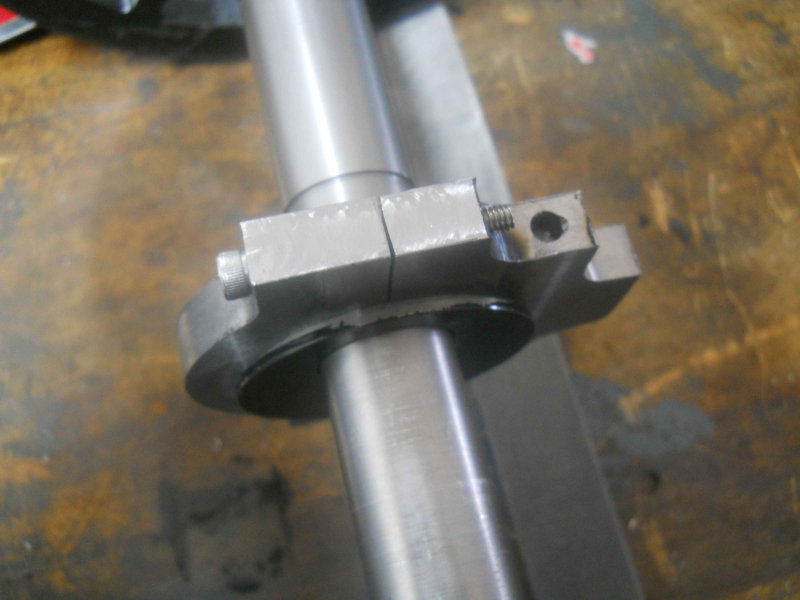
It's a little "tighter" than Kozo seems to like, but I imagine it will wear a bit early on. I drilled the oil holes before milling the bore, so what remains is to mill a slot for the eccentric rod,
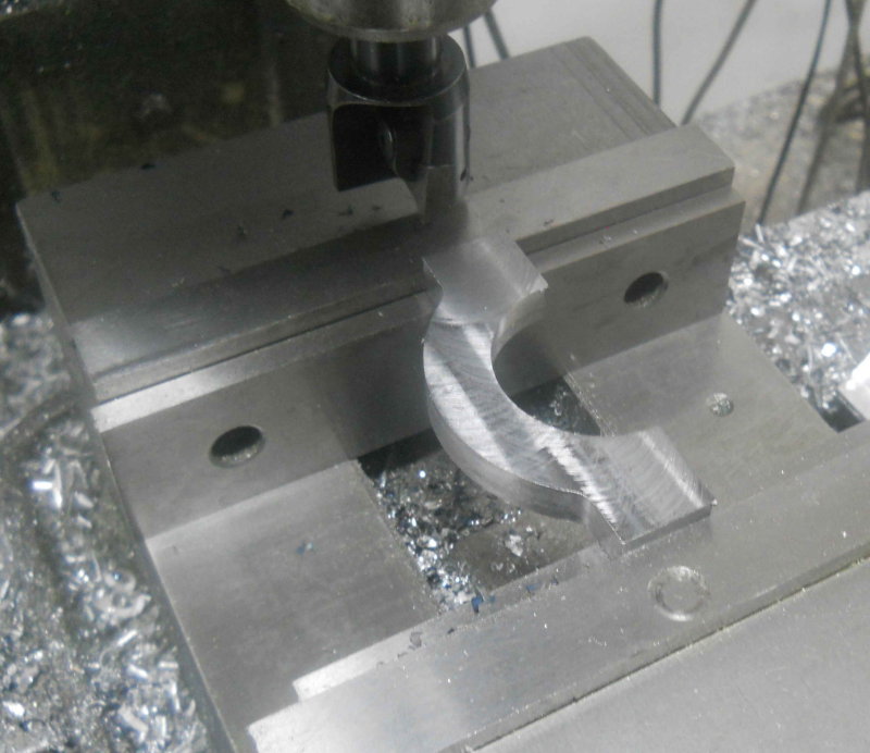
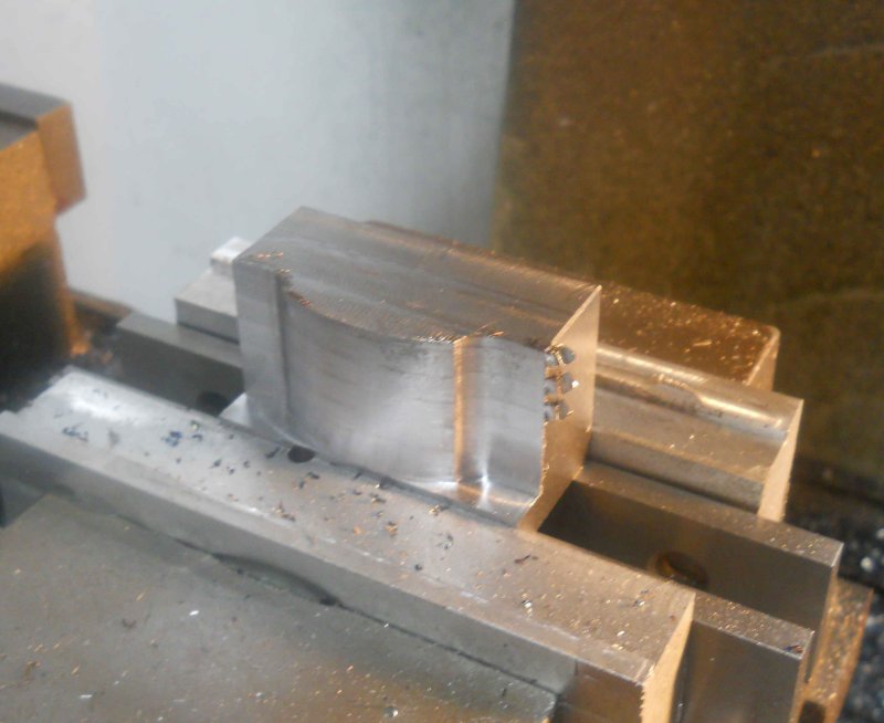
I started to mill the rod this morning, but broke 2 carbide endmills trying some new "techniques" and ruining the prepared stock, so to avoid depressing myself further I switched my attention to the front coupler pocket. Rather than soldering together various pieces, I intend to mill it from a single steel block. Starting with a piece of 1/2" square CRS stock, I milled the starting block to external dimensions on the Bridgeport. Here it is posed where the final piece will mount on the front bumper.
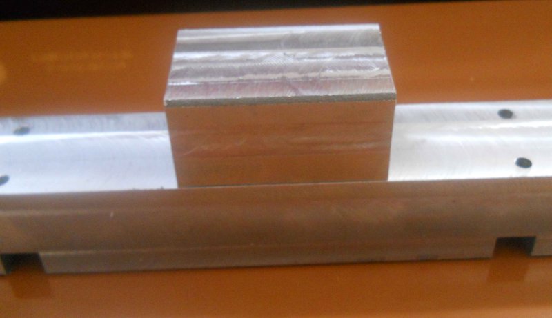
The first operation was the radius for the front:
Then side flanges:
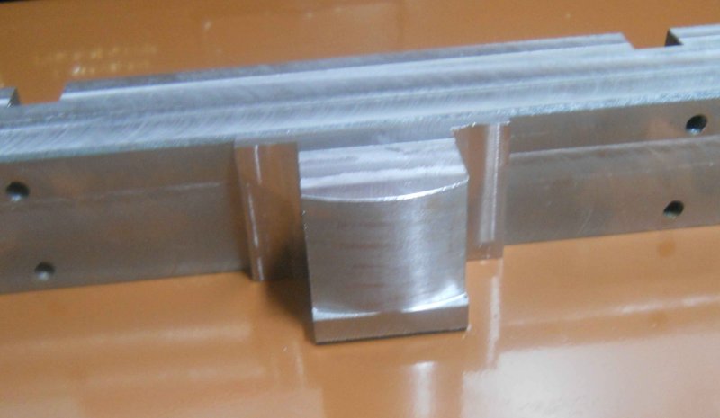
There are two pockets yet to be milled plus drilling and some other finishing. I'm not going to drill the hole for the coupler pin until I actually have a coupler to fit.
Then the part is chucked upside down on the Bridgeport, and the support material whittled away with a face mill. I rather like this method of "fixturing" as it results in a good finish on both sides.
The other half of th strap was machined the same way. Then with drilling and tapping, the two halves can be screwed together. I then faced both sides of the combined strap with the face mill to get the sides flat and parallel before going back to the CNC mill.
The center bore had been left a good 1/8" small when milling the halves, and now with them together the finish diameter can be milled.
Now the fit to the eccentric:
It's a little "tighter" than Kozo seems to like, but I imagine it will wear a bit early on. I drilled the oil holes before milling the bore, so what remains is to mill a slot for the eccentric rod,
I started to mill the rod this morning, but broke 2 carbide endmills trying some new "techniques" and ruining the prepared stock, so to avoid depressing myself further I switched my attention to the front coupler pocket. Rather than soldering together various pieces, I intend to mill it from a single steel block. Starting with a piece of 1/2" square CRS stock, I milled the starting block to external dimensions on the Bridgeport. Here it is posed where the final piece will mount on the front bumper.
The first operation was the radius for the front:
Then side flanges:
There are two pockets yet to be milled plus drilling and some other finishing. I'm not going to drill the hole for the coupler pin until I actually have a coupler to fit.
- Joined
- Jun 4, 2008
- Messages
- 3,285
- Reaction score
- 630
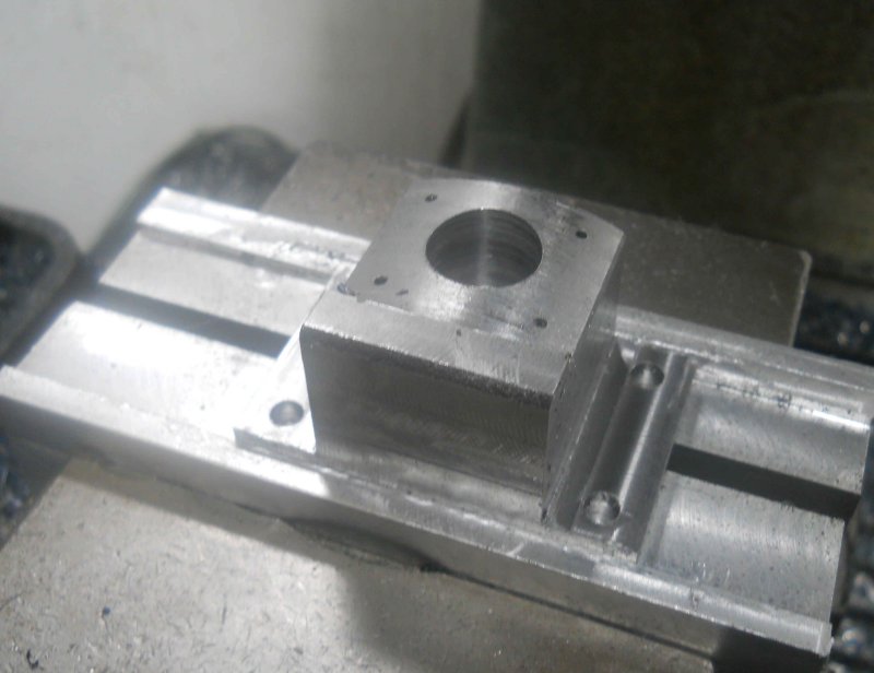
Today I finished up the coupler pocket. Did all the drilling on the Bridgeport - 1/16" corner holes for the main pocket (which may be unnecessary), mounting holes for 8-32 screws in the flanges, and a 5/8" hole in the center pocket for material removal. Then onto the CNC mill to mill out the coupler pocket. I retrospect, this would have been just as easy to do manually.
The bottom pocket and the bottom flange angles were milled on the Bridgeport.
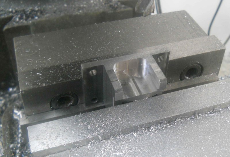
Ready for paint and a coupler for fitting. I can file out the corners if needed.
The bottom pocket and the bottom flange angles were milled on the Bridgeport.
Ready for paint and a coupler for fitting. I can file out the corners if needed.
- Joined
- Jun 4, 2008
- Messages
- 3,285
- Reaction score
- 630
With only an hour or so of shop time today, I contented myself with machining the slot in the eccentric strap where the rod fits. The plan specifies a rather awkward 5/32 width, for which I don't have an endmill. And in any case, milling a deep (.4") slot with a 1/8" endmill is not that easy either. So I decided to first cut the slot with a 1/16" slitting saw, and then widen with with a 1/8" endmill. While the G-Wizard feed&speed calculator gave a reasonable result of 180 RPM and 6 IPM, there was no real counsel on DOC. I ended up cutting repeatedly at .02, which took a while.
Then my cheapo Chinese carbide endmill gave up the ghost after cutting a single pass at .015 DOC and 1 IPM. Luckily my medium priced Chinese endmill did survive to the end of the slot. So far I've broken 3 of the 1/8" 2-flute carbide endmills from Richon tools by barely breathing on them. While their 1/2" carbide seems OK for roughing work, these small ones are just too fragile for anything.
Then my cheapo Chinese carbide endmill gave up the ghost after cutting a single pass at .015 DOC and 1 IPM. Luckily my medium priced Chinese endmill did survive to the end of the slot. So far I've broken 3 of the 1/8" 2-flute carbide endmills from Richon tools by barely breathing on them.
While their 1/2" carbide seems OK for roughing work, these small ones are just too fragile for anything.- Joined
- Jun 4, 2008
- Messages
- 3,285
- Reaction score
- 630
I didn't get a whole lot of shop time over the past few days, but did machine the eccentric rod to go with the strap.
You can see where an overdeep cut with the slitting saw heated up the strap, but that will be painted over. While Kozo uses two screws to attach the rod to the strap, I decided to just use the Loctite 620, which worked well.
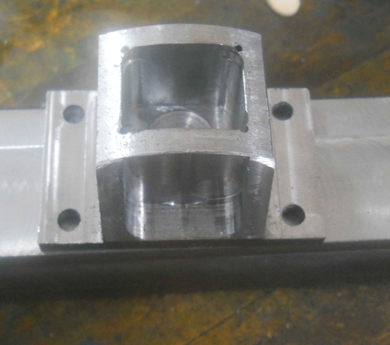
I had bought some 2" square CRS a week or two ago, so I decided to start on the tee. i sawed of a chuck about an inch longer than needed, and machined the long sides to 1.875 x 1.625 as per the plans. Squaring the ends with side flutes of a long end ill wasn't a success, as I got a lot of chatter even with a very shallow DOC. I decided to see how it would work on the lathe anfd 4-jaw chuck.
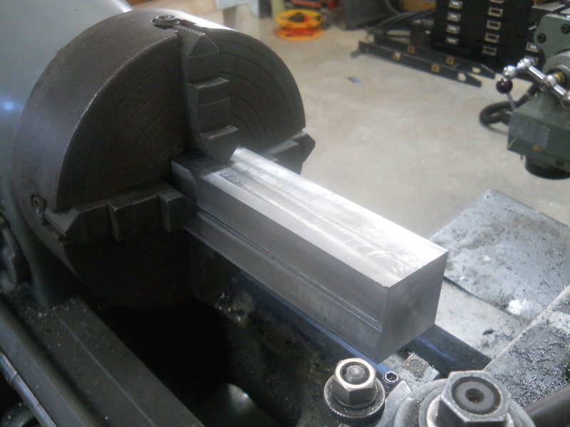
I was a bit nervous with so much sticking out (7" with only 1" jaw length), but a facing cut produced a good result, even if the DOC was about .01". The length is still 3/4" longer than needed; I expect to mill to final length once the cylinders are present to be fitted.
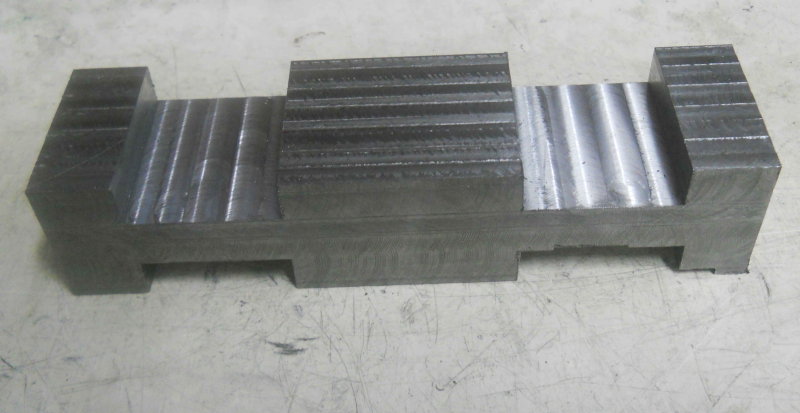
Since the piece is longer than needed, I milled the 4 slots using the center as the datum.
I need to drill two through holes lengthwise for steam supply and exhaust. I'll need to drill these halfway from each end. Given the facing cut on the lathe, I assume I could drill these on the lathe, but it seems easier to drill vertically on the Bridgeport.
You can see where an overdeep cut with the slitting saw heated up the strap, but that will be painted over. While Kozo uses two screws to attach the rod to the strap, I decided to just use the Loctite 620, which worked well.
I had bought some 2" square CRS a week or two ago, so I decided to start on the tee. i sawed of a chuck about an inch longer than needed, and machined the long sides to 1.875 x 1.625 as per the plans. Squaring the ends with side flutes of a long end ill wasn't a success, as I got a lot of chatter even with a very shallow DOC. I decided to see how it would work on the lathe anfd 4-jaw chuck.
I was a bit nervous with so much sticking out (7" with only 1" jaw length), but a facing cut produced a good result, even if the DOC was about .01". The length is still 3/4" longer than needed; I expect to mill to final length once the cylinders are present to be fitted.
Since the piece is longer than needed, I milled the 4 slots using the center as the datum.
I need to drill two through holes lengthwise for steam supply and exhaust. I'll need to drill these halfway from each end. Given the facing cut on the lathe, I assume I could drill these on the lathe, but it seems easier to drill vertically on the Bridgeport.
- Joined
- Jun 4, 2008
- Messages
- 3,285
- Reaction score
- 630
Yesterday I finished up drilling the steam and exhaust passages in the Tee. Lots of pecking and chip clearing to get 3.5" deep holes. The steam passage is 9/32 and the exhaust is 11/32. Still to do is take 1/4" off each end; the faces need to end up exactly level with the outside of the frame. Then it's milling the 45 degree angles on the ends to fit through the holes in the frame.
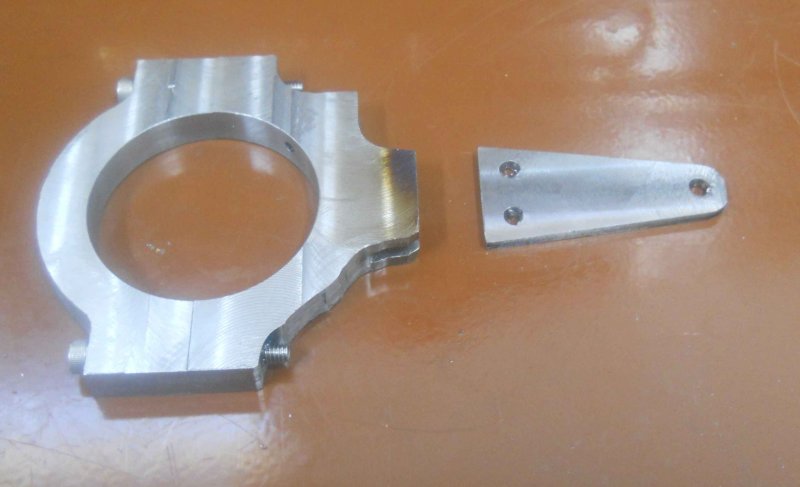
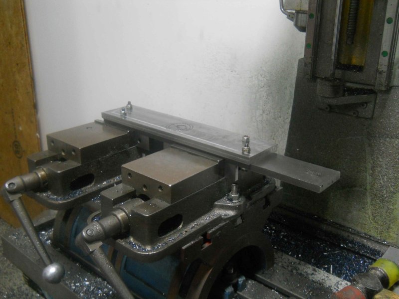
Today I made the second support plate and bracket (made the first some time ago, but ran out of material then). Rather than mill the bracket out of square stock, this time I had some angle iron. That said, it wasn't any quicker to make.
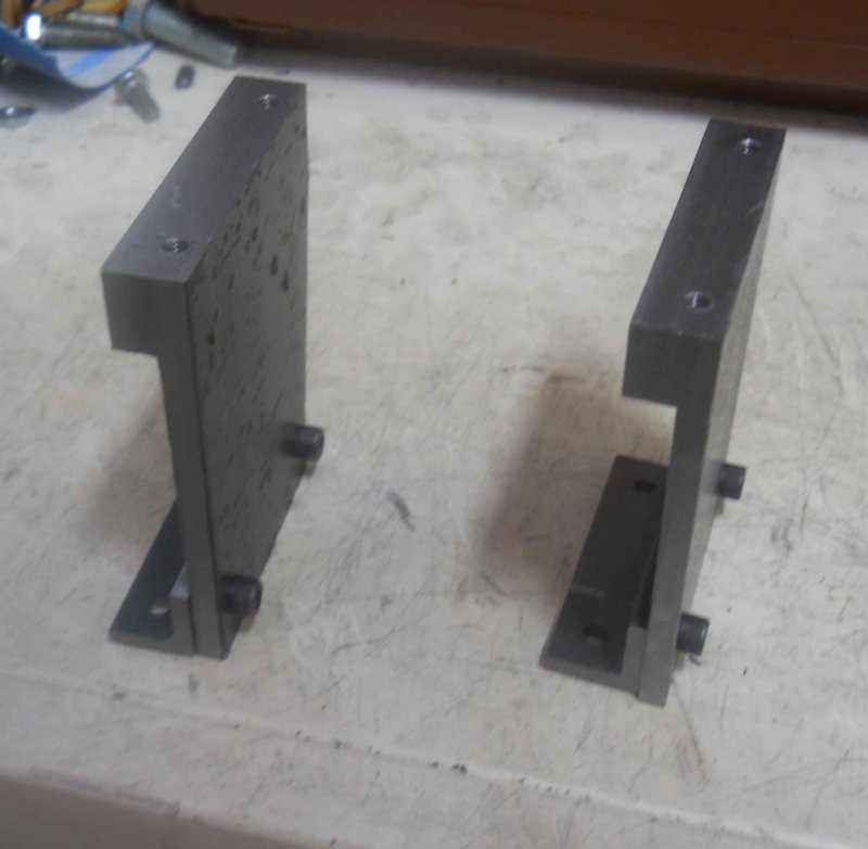
I misread the drawing and drilled the top holes 1/16" too close to the edge, so I'll need to account for that when I drill the running boards.
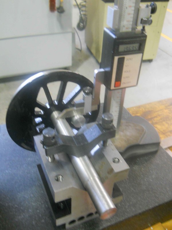
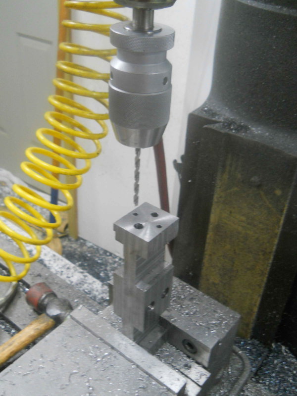
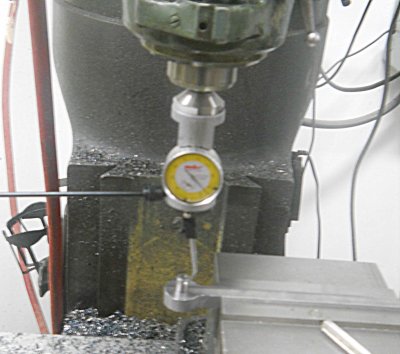
Finally today, I wanted to measure the center to center distance between the two axles, as that will be the distance needed for positioning the bushings in the connecting rods. Not having any accurate hand tools for measuring 12+ inches, I came up with this setup on the mill table.
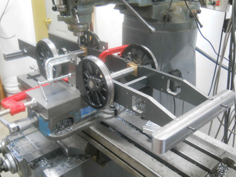
Then I could use an edge finder and DRO to measure. The plans call for 11", and I measured 11.009 in the center and 11.003/.004 at the sides. I am wondering how much slack is permissible here. I assume that a few thousands clearance in the bushings can accommodate movement as the wheels move about. Perhaps experienced builders can comment.
I also measured the outside frame widths at front and read. At the front where the tee needs to match, I measured 6.548 vs. 6.562 plan, while at the rear it was 6.525.
Today I made the second support plate and bracket (made the first some time ago, but ran out of material then). Rather than mill the bracket out of square stock, this time I had some angle iron. That said, it wasn't any quicker to make.
I misread the drawing and drilled the top holes 1/16" too close to the edge, so I'll need to account for that when I drill the running boards.
Finally today, I wanted to measure the center to center distance between the two axles, as that will be the distance needed for positioning the bushings in the connecting rods. Not having any accurate hand tools for measuring 12+ inches, I came up with this setup on the mill table.
Then I could use an edge finder and DRO to measure. The plans call for 11", and I measured 11.009 in the center and 11.003/.004 at the sides. I am wondering how much slack is permissible here. I assume that a few thousands clearance in the bushings can accommodate movement as the wheels move about. Perhaps experienced builders can comment.
I also measured the outside frame widths at front and read. At the front where the tee needs to match, I measured 6.548 vs. 6.562 plan, while at the rear it was 6.525.
- Joined
- Jun 4, 2008
- Messages
- 3,285
- Reaction score
- 630
After a long weekend of family obligations, I got into the shop for a few hours each the past couple of days. Yesterday I decided to make the water pump plunger as it should go quick and I had a length of 1/2" 303SS rod available. The turning went quickly as other than getting the correct length, there were only the bevels on each end. I then used a square collet block to drill the cross pin hole, and then only the slot for the eccentric rod was left to do.
My plan was to cut it with the 1/16 slitting saw and then mill to 1/8 width. However, using the 92 RPM in back gear called-for by G-Wizard, the saw stalled without cutting. Adding some RPM was no better. So now I need to try to mill it. Not having much confidence is a 1/8 endmill cutting a deep slot, I decided to first use the hacksaw to make a slit 1/2" deep. This gave a place for swarf to fall. Then I just took .010 deep passes, and widened the slot .01 on each side every .05 of depth. Took quite a while but got there eventually.
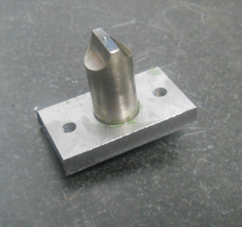
Then made the exhaust deflector; rather than turning in one piece, I did the shaft and baseplate separately and joined with loctite.
Finally today turned the bronze O-ring retainer/bushing for the water pump. I modified the OD to 3/4 rather than the scaled .772 in order to be able to ream the matching hole in the pump.
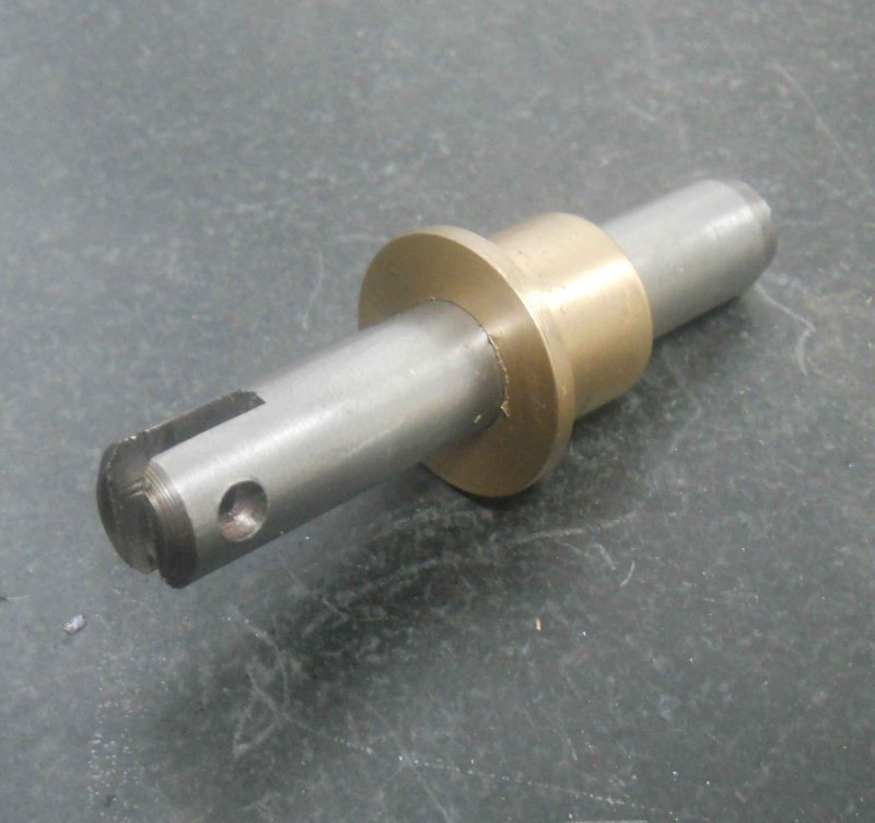
Before deciding to finish the retainer, I had started to want to make the crank pins. Before deciding on the OD of the pins, I thought I'd better see what reamers I have to ream the bushings that go over them. Kozo used .281, which scales to .562. The closest reamer I own is 14mm or .551, so that's what they will be. This gives the ID of the bushings, and the OD needs to match the bores in the side and main rods. Kozo used 9mm for the rods, but not having an 18mm reamer my choices are 16mm (.6299) and .750. I drew the main rods in CAD, and .750 will work. If I use .6299 with a .551 ID, then the wall thickness will be only .04, which seems pretty thin.
I need to draw the side rods in CAD to see how a .75 bore will work with the other dimensions,
My plan was to cut it with the 1/16 slitting saw and then mill to 1/8 width. However, using the 92 RPM in back gear called-for by G-Wizard, the saw stalled without cutting. Adding some RPM was no better. So now I need to try to mill it. Not having much confidence is a 1/8 endmill cutting a deep slot, I decided to first use the hacksaw to make a slit 1/2" deep. This gave a place for swarf to fall. Then I just took .010 deep passes, and widened the slot .01 on each side every .05 of depth. Took quite a while but got there eventually.
Then made the exhaust deflector; rather than turning in one piece, I did the shaft and baseplate separately and joined with loctite.
Finally today turned the bronze O-ring retainer/bushing for the water pump. I modified the OD to 3/4 rather than the scaled .772 in order to be able to ream the matching hole in the pump.
Before deciding to finish the retainer, I had started to want to make the crank pins. Before deciding on the OD of the pins, I thought I'd better see what reamers I have to ream the bushings that go over them. Kozo used .281, which scales to .562. The closest reamer I own is 14mm or .551, so that's what they will be. This gives the ID of the bushings, and the OD needs to match the bores in the side and main rods. Kozo used 9mm for the rods, but not having an 18mm reamer my choices are 16mm (.6299) and .750. I drew the main rods in CAD, and .750 will work. If I use .6299 with a .551 ID, then the wall thickness will be only .04, which seems pretty thin.
I need to draw the side rods in CAD to see how a .75 bore will work with the other dimensions,
- Joined
- Jun 4, 2008
- Messages
- 3,285
- Reaction score
- 630
After some drawing and calculating, I got in the shop to turn the crank pins. Small dia. is .500 to match the holes in the wheels, and .546 to give clearance for the .551 bushing ID.
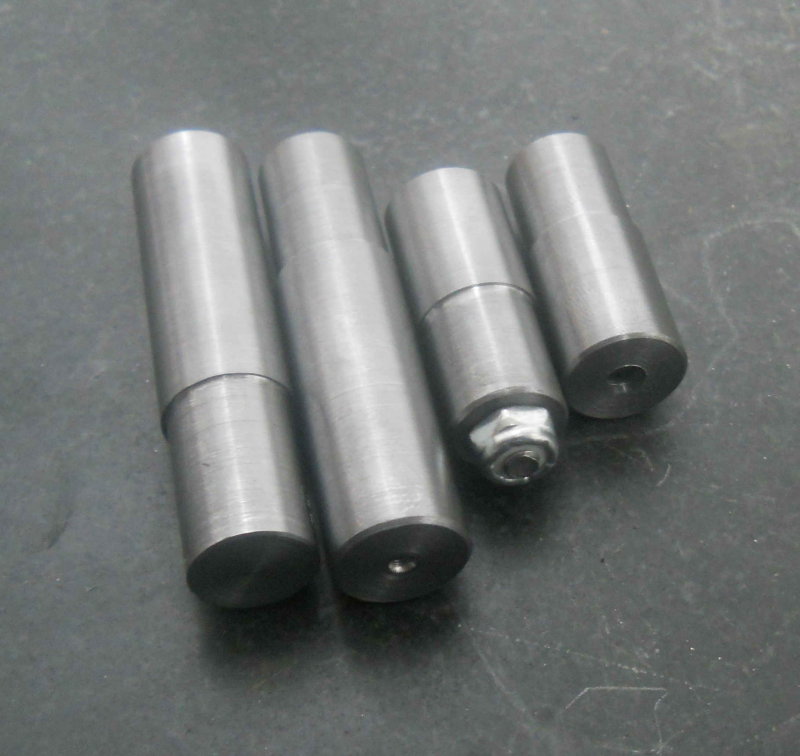
The locknut was to test the clearance of a threaded side rod pin, as I neglected to bore a place in the back of the wheel for an e-clip
.
The locknut was to test the clearance of a threaded side rod pin, as I neglected to bore a place in the back of the wheel for an e-clip
.
- Joined
- Jun 4, 2008
- Messages
- 3,285
- Reaction score
- 630
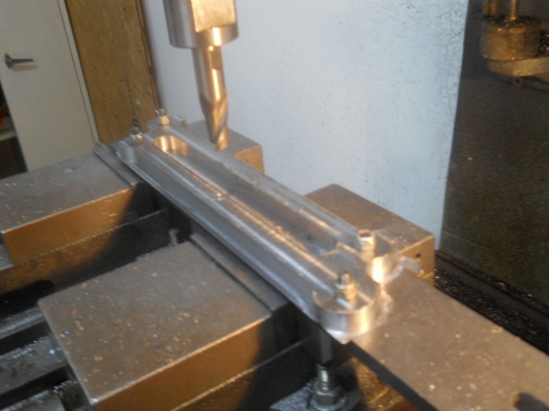
The past few days I've made a start on the side rods. Since my supply of 1/2" CRS is 3" wide, I decided to just make both at the same time from one piece of stock on the CNC mill. So I cut off a piece 13.5" long, squared the edges, and drilled two pairs of reamed .375 holes 11.004" apart. Then I got a piece of donated CRS 2.375" wide; drilled and reamed matching holes. The "locator" pins which pass through the holes keep the stock from moving as it is machined. I made these pins from drill rod. They are a few thou smaller than the combined thicknesses of the jig plate and stock, through drilled 1/4".
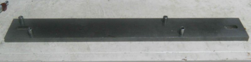
Now I could mate the stock to the jig and secure it with 4 1/4" screws and nylon locknuts (locking nuts are needed as the vibration from milling can loosen normal nuts.
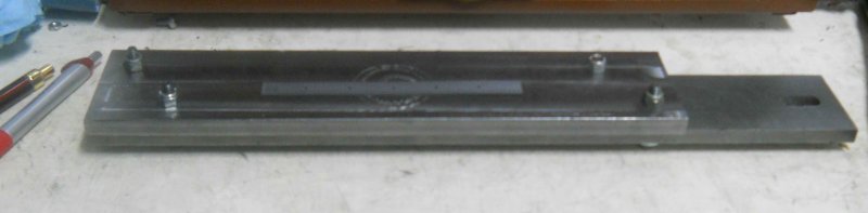
The jig plate is mounted on the CNC milling vises. I like these two 4" vises vs. a 6" vise as I can hold longer pieces.
The first operation was to rough out the shapes using a 3/4" HSS 2-flute endmill.
Then two additional passes with a 7/16" carbide 4-flute endmill, and I end up with these:
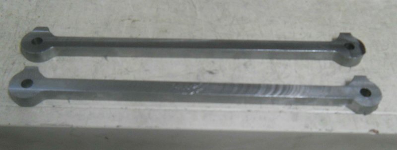
All the rest of the work on these will be manual milling.
I learned quite few things doing these pieces, and making the main rods should go a lot faster. One thing that stands out is that I should make each singly from narrower stock. The necessity to rough out the "valley" between the two means a slot cut, and that needs a much slower feed rate. Machining a single from the outside in can be done considerably faster with deeper cuts.
Work remaining is to drilling/reaming the holes for the bushing, counterboring one hole in each for the retainer pin, drilling the oiler holes, and narrowing the "neck". The pieces are also .08 too thick, so that will be faced off to spec.
Now I could mate the stock to the jig and secure it with 4 1/4" screws and nylon locknuts (locking nuts are needed as the vibration from milling can loosen normal nuts.
The jig plate is mounted on the CNC milling vises. I like these two 4" vises vs. a 6" vise as I can hold longer pieces.
The first operation was to rough out the shapes using a 3/4" HSS 2-flute endmill.
Then two additional passes with a 7/16" carbide 4-flute endmill, and I end up with these:
All the rest of the work on these will be manual milling.
I learned quite few things doing these pieces, and making the main rods should go a lot faster. One thing that stands out is that I should make each singly from narrower stock. The necessity to rough out the "valley" between the two means a slot cut, and that needs a much slower feed rate. Machining a single from the outside in can be done considerably faster with deeper cuts.
Work remaining is to drilling/reaming the holes for the bushing, counterboring one hole in each for the retainer pin, drilling the oiler holes, and narrowing the "neck". The pieces are also .08 too thick, so that will be faced off to spec.
- Joined
- Jun 4, 2008
- Messages
- 3,285
- Reaction score
- 630
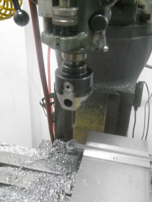
Yesterday and today more work on the side rods. I needed to accurately enlarge the 4 crank pin holes to .75" (i.e., keeping the 11.004 hole center separation). After mounting the ron the vise, the I used a locator pin plus the coaxial centering gadget to center the spindle over the hole.
With the table locked, I enlarged the hole by drilling by 1/16ths up to 11/16.
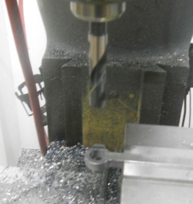
Then a further 1/32 via the boring head (This will correct any wandering of the hole caused by the drills).
Finally the 3/4 reamer.
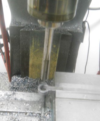
Repeat 4 times.
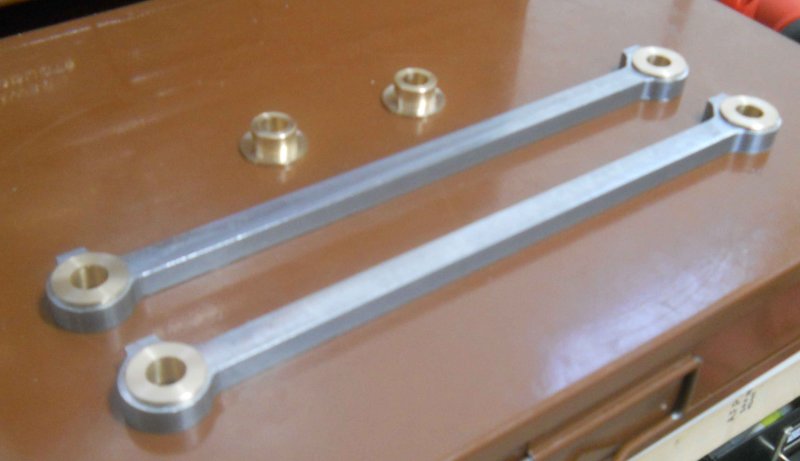
Then it was on to the lathe to turn phosphor bronze bushings for the rods, plus two for the large end of the main rod. The bushings were reamed to 1/2", and will be enlarged to fit the crank pins once they have been loctited to the rods. For now it's just a push fit.
With the table locked, I enlarged the hole by drilling by 1/16ths up to 11/16.
Then a further 1/32 via the boring head (This will correct any wandering of the hole caused by the drills).
Finally the 3/4 reamer.
Repeat 4 times.
Then it was on to the lathe to turn phosphor bronze bushings for the rods, plus two for the large end of the main rod. The bushings were reamed to 1/2", and will be enlarged to fit the crank pins once they have been loctited to the rods. For now it's just a push fit.
- Joined
- Jun 4, 2008
- Messages
- 3,285
- Reaction score
- 630
Today I finished profiling the sides of the side rods and loctited the bushings. Rather than the side flutes of a 1/4" endmill for the radii, I used the end of a 1/4" ball mill. This saved making the jig that Kozo suggests.
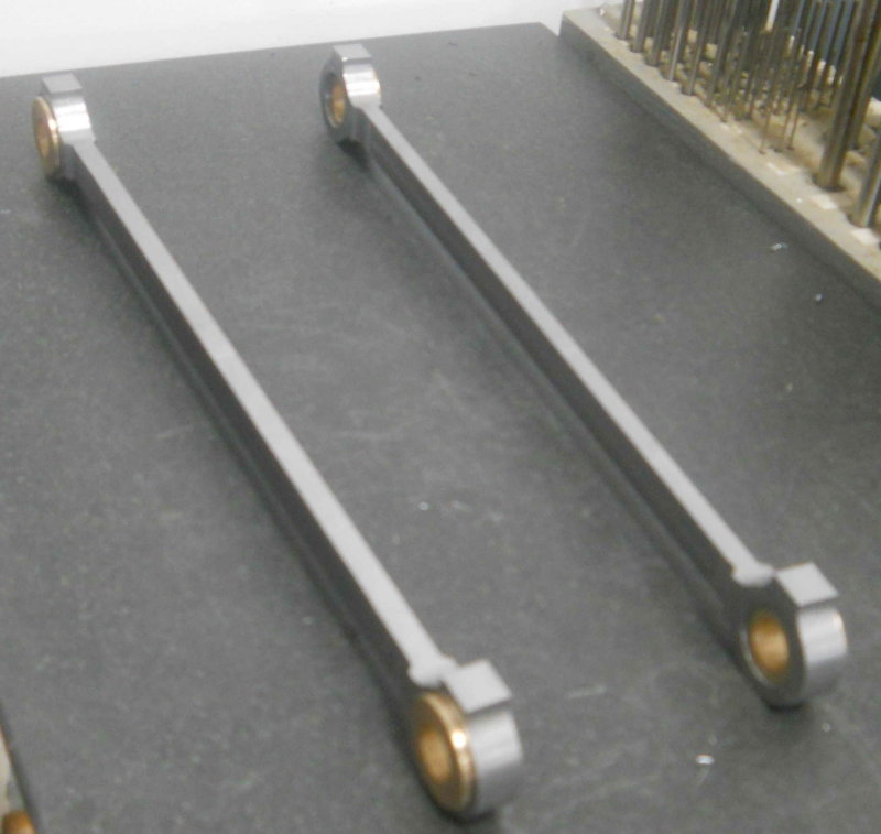
Next I'll ream/bore the bushings and finally see if how they work mounted to the drivers.
Still to do is drilling and tapping for oil cups on the ends. That's wait on a make/buy decision on the oil cups.
Next I'll ream/bore the bushings and finally see if how they work mounted to the drivers.
Still to do is drilling and tapping for oil cups on the ends. That's wait on a make/buy decision on the oil cups.
- Joined
- Jun 4, 2008
- Messages
- 3,285
- Reaction score
- 630
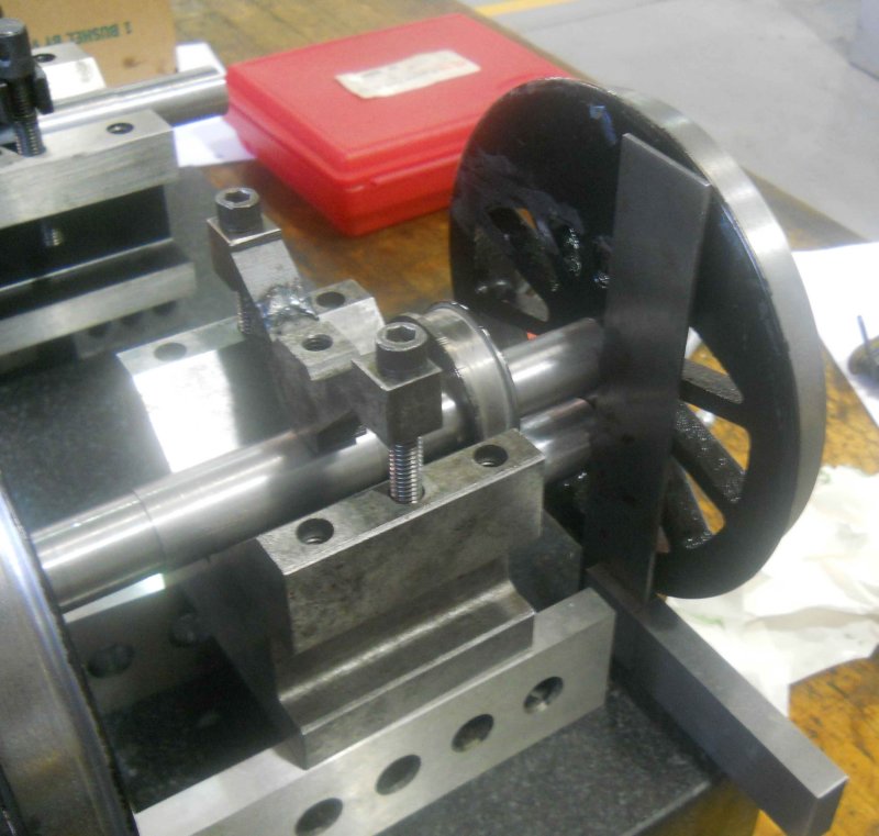
A "milestone" today. I finished drilling/reaming the side rod bushings and mounted the rods and crank pins onto the drivers. No binding, smooth as silk. So the measurements and quartering look good. That's a load off.
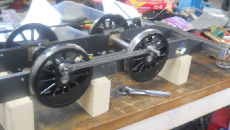
I plan to do the main rods and reverse cranks next, so that I can trim the crank pins to length. I'll also be able then to measure the centerline separationof the main rods, and move on to the cylinders.
I plan to do the main rods and reverse cranks next, so that I can trim the crank pins to length. I'll also be able then to measure the centerline separationof the main rods, and move on to the cylinders.
Similar threads
- Replies
- 111
- Views
- 21K
- Replies
- 11
- Views
- 6K