Kozo A3 in 1.5" scale

Home Model Engine Machinist Forum

Help Support Home Model Engine Machinist Forum:

This site may earn a commission from merchant affiliate links, including eBay, Amazon, and others.
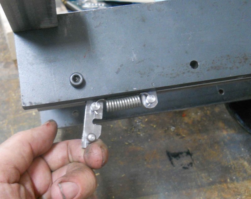
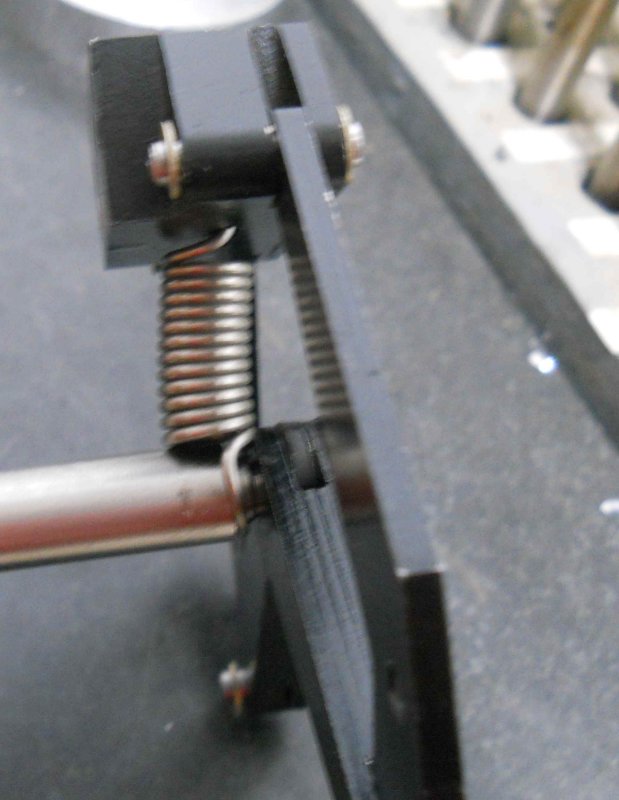
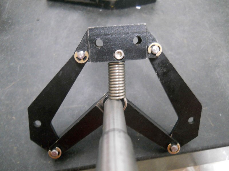
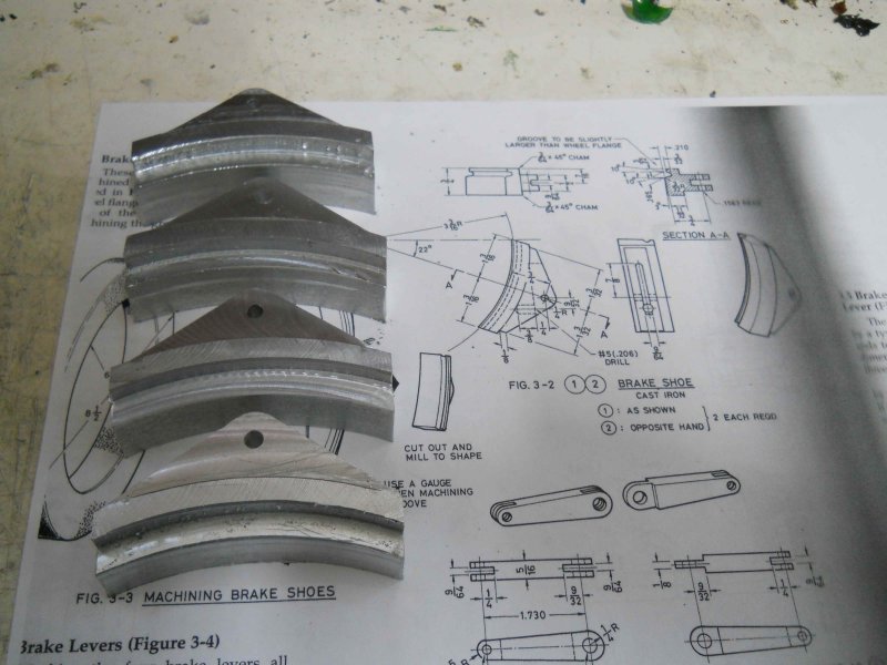
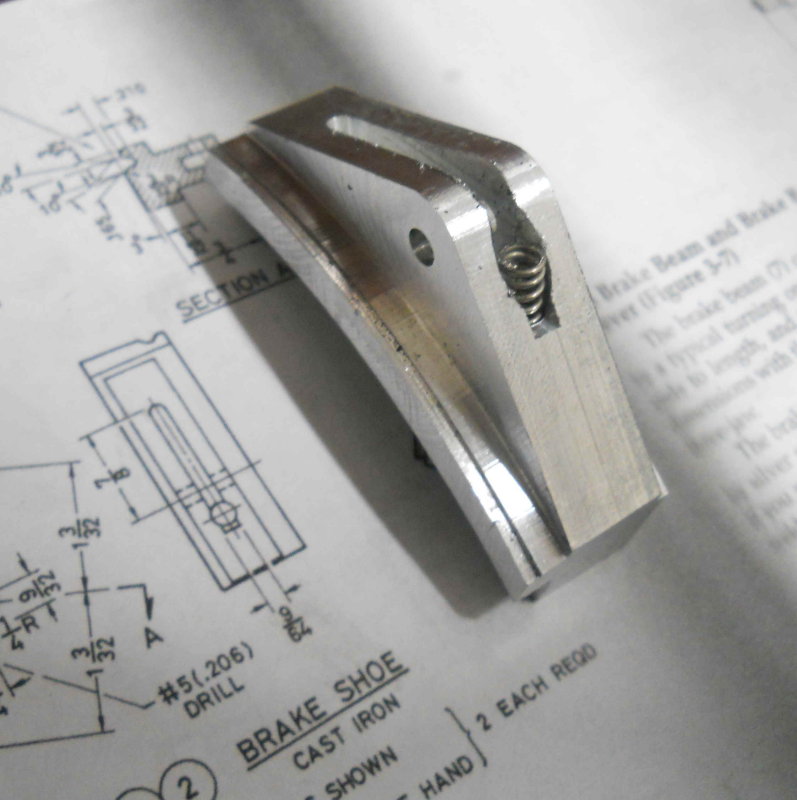
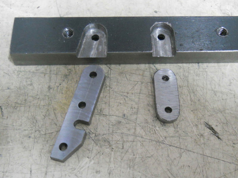
After remaking the two bad pins and grooving the brake bar, I found the SS springs needed for the brake system at McMaster-Carr, so ordered them. Now, it's time for brake shoes. I had read that Dave Sciavi has used aluminum for loco brake shoes, so I'm trying that first. The shoes require three setups, two on CNC and the final on the Bridgeport. Here's my experiment after op 1:

large.jpg


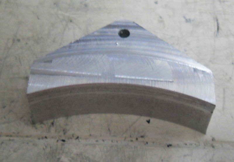
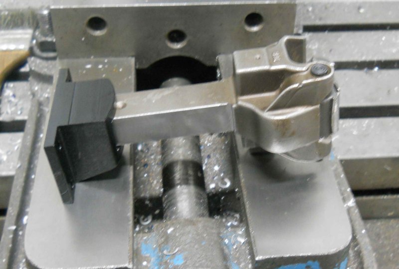
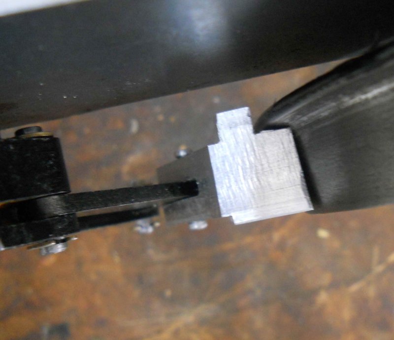
While the profiling is straightforward, train wheel treads are beveled 3 degrees. I approximated this by cutting tiny "ledges" at .025" separation. I had neglected to realize that this gives the larger radius at the top (i.e, top is inner side), so that the top needs the relief for the wheel flange, and as well the cheek cut needs to be 1/8" deeper. In any case, both the angle and radius of the face are good fits to my drivers, so fixing this one and making 3 more is straightforward.


Real nice work K. I am enjoying following your progress.

 
I hadn't checked in for a while K, but the progress is really amazing. Top notch workmanship and wonderful pictures also. Once you have the chassis running on air I do hope you will post a video too.

Bill
 
Thanks to all who are following along. My goal is to have something that works first, and looks pretty second.

I got the return springs delivered this afternoon and tried a quick fit. There are a couple of problems here:

large.jpg


large.jpg


I think that having the spring off center will retract the brake shoes unevenly. So turning the brake beam end smaller to fit the spring's loop should bring the spring onto the centerline. Whether having the spring inclined side to side has an effect remains to be seen. To correct that I'd need to grind the head of the level link to clear the spring coil.
 
After revamping the CNC code, I machined 4 brakes shoes from 6061:

large.jpg


The next ops are on the Bridgeport milling a slot for the brake lever and drilling a hole for the spring. I used angle bars to set the shoe in the vise canted 22 degrees. A protractor would have been a bit easier.

large.jpg


Hopefully I can finish the other 3 next time; milling deep slots with a 1/8" endmill is nerve-wracking.
 
Today I finished the other 3 brake shoes, and worked on the assembly. I solved the spring position problem by turning a groove in the brake beam to retain the end of the spring, giving clearance to both the beam and levers. Here's what I got with one of the shoes attached:

large.jpg


I am not totally sure how best to assemble these components with the drivers and frames, so I'll wait to pin the shoes until I do a trial assembly.

A friend lent me a Tom Bee coupler until my order shows up, so I wanted to fit it to my coupler pocket. This meant milling 3 sides of the shank. I'll finish milling the end radius and then check for angle movement of the coupler. Once I'm happy with the final shaft dimensions, I'll cut it short and mill the final length.

large.jpg


The coupler is larger than Kozo's scaled-up version (2" high vs. 1-1/2), so it may look a little big for the engine, but as this isn't a museum quality build I'll live with it.

If the brakes fit properly, I plan to assemble with the springs and take it out to the RR to see how it tracks next week.
 
Today I assembled the shoes and brake mechanism, then started to re-assemble the frame and drivers. Assuming that I'd be able to do the track test this week, I put small pieces of gauze into the pockets of the axle boxes and oiled them with way oil. I need to think up a good way to oil the axle boxes as unscrewing the two halves of each will be hard to do when the engine is complete.

With the frame and drivers upside down, it was straightforward to attach the complete brake assemly to the frame between the drivers. Initially the position of the shoes relative to the drivers looked good, and while there was some friction, the wheels and axles could turn.

large.jpg


However, when I set the frame upright and pressed down on the brake beam, the wheels and shoes locked up tight and would not release. This seems to be the issue:

large.jpg


The inner edge of the brake jams into the inner radius of the wheel profile. I think the solution is to reduce mill a larger relief for the wheel flange. The brake surface seems to align very well with the wheel circumference with about 1/8" clearance all around. I'll generate the necessary CNC code tonight and remill the shoes the next time in the shop.

Next I CNC milled a radius on the end of the coupler shank and drilled a hole for the pin:

large.jpg


Then a test fit to the frame:

large.jpg


I'm going to hold off on drilling mounting holes for the couple pocket until I verify the coupler height at the track. There's about 20 degrees of side-to-side swing as is, but I may need to narrow the coupler shank to get more angle.

 
Those brakes look pretty serious....no doubt they'll work well

Great Job Kvom! :bow:

Dave
 
I didn't feel like starting any complicated pieces today, so I decided to finish off the grate supports, one of the first parts I made in this project (back on December 8 ). I seem to have a habit of making "partial" parts leaving some details to be polished off later. This is probably a bad habit. In any case, I needed to machine pockets on the sides opposite the grate. Despite being simple in theory, I still spent all afternoon.

Here are the results:

large.jpg


The two pockets on the right side support are for the latch for the ash pan. Kozo suggests SS, but I just made them from CRS, and will paint.

large.jpg


Of course now I need the 5 pieces that go in those holes, so there's two more unfinished parts.

I won't get much shop time the rest of the week as the floors in the house are being refinished, and tracking in swarf is a big no-no.
 
Hi Kavom
great build :)
A steam engine is on the list :)
I have the same problem with partial parts, which I really need to overcome as I often make it so much harder on myself then would have been the case if i'd finished the bit before taking it out of the lathe or mill.
Glad to see i'm not the only one :big:
Pete
 
Today was the first trial of the chassis on the tracks at my home club in Canton, GA. The assembly performed very well, with no problems on any of the curves or tight portions of the switches or frogs. With such a short wheelbase, the engine could probably handle a 20' radius curve according to one of the members present.

Here's a short video taken from the riding car.

[ame]http://www.youtube.com/watch?v=M0we2yqJo0M[/ame]

And sitting on the tracks afterwards.

large.jpg


The coupler height seems good, so I will drill and tap the buffer beam to mount the coupler pocket, plus shorten the coupler shank. For the next track run I want to have the side rods installed.
 
After yesterday's trial run, I proceeded to mount the coupler to the front bolster, cut down the coupler shank, and make a coupler pin to replace the screw I had been testing for fit.

large.jpg


Then, based on advice from an experienced builder in the club, I wanted to replace the retaining pin used to keep the side rods on the front crank pin. Kozo's design has a e-clip in a hollow at the back of the driver where it would be inaccessible after assembly. After trying a few things, I finished by using a brass washer held in place with a flat head screw; I countersunk both the crank pin and washer to get the screw head flat to the washer. A trial eyeball fit indicates that there won't be any interference with the conrod.

large.jpg


Despite appearances, the washer does not contact the side rod.
 
This was my last day in the shop for a while. I decided to finish the parts for the ash pan latch that I started earlier. Needed to make some smallish pieces but all was for the best. These are really finicky in 3/4 scale I imagine. Here's a trial fit photo:

large.jpg


I still need to silver solder all the bits together. The spring is the same as the return spring for the brakes, and is nice and firm. They came in a pack of 3, which was handy.
 
I like that KVOM...anthing that makes the engine more serviceable will be appreciated later!

Dave
 
Let me tell ya KVOM....once you start firing it...she won't be "pretty" anymore, and you will be working on her....trust me anything that makes that easier you will appreciate! :)

Dave
 
When its fully built up, will the chassis settle on the springs and make the coupler too low?
 
Back
Top