Kozo A3 in 1.5" scale

Home Model Engine Machinist Forum

Help Support Home Model Engine Machinist Forum:

This site may earn a commission from merchant affiliate links, including eBay, Amazon, and others.
Kvom

I don't want to start a lengthy off topic debate on your thread but thanks for the insight into the amount of work required for CAD/CAM. I'm torn about going the CNC route and clearly there are advantages even if it means available shop time spent in front of a computer. Trouble is that's what I do all day and the shop is a bit of break from all that.

....................back to the A3

Pete

 
Zee, The driver wasn't damaged, but afterwards the setup would wobble.

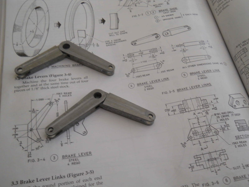
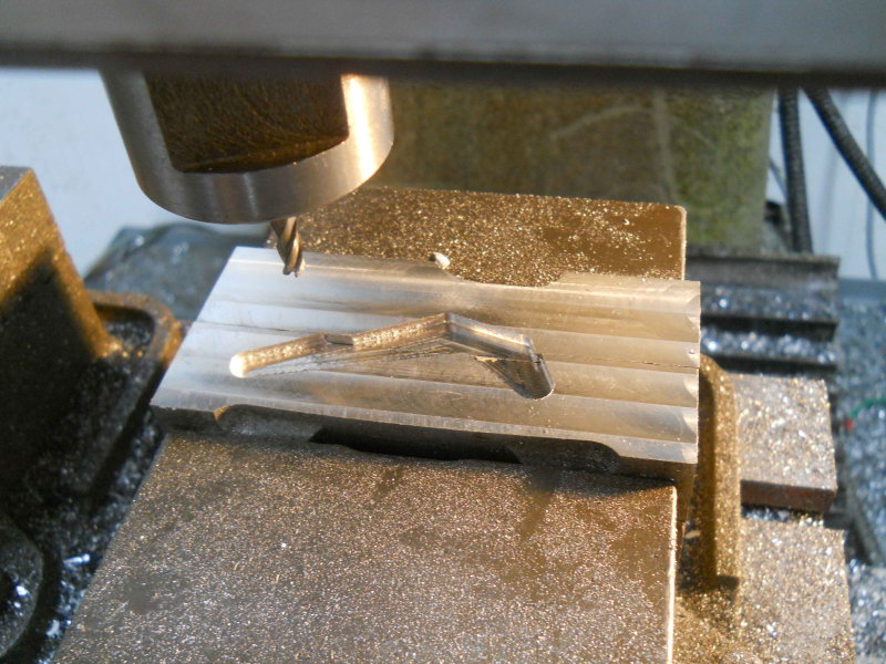
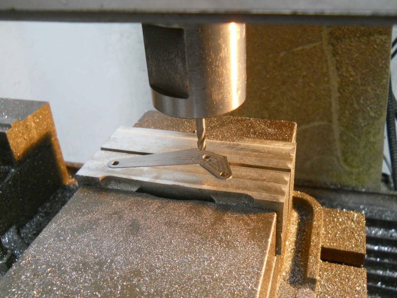
doubletop, if you don't use a CNC mill, then the rounded parts need to be approached in one of these ways:

1) ignore them and leave them square or polygonal, as they are mostly for appearance rather than fit.
2) Form them with a grinder or sander
3) Build a rounding table; there are a number of threads on HMEM about how to do this
4) Use a rotab, although the setups could be really time consuming

Otherwise, the "wierd angle" parts can be milled via angle bar setups.

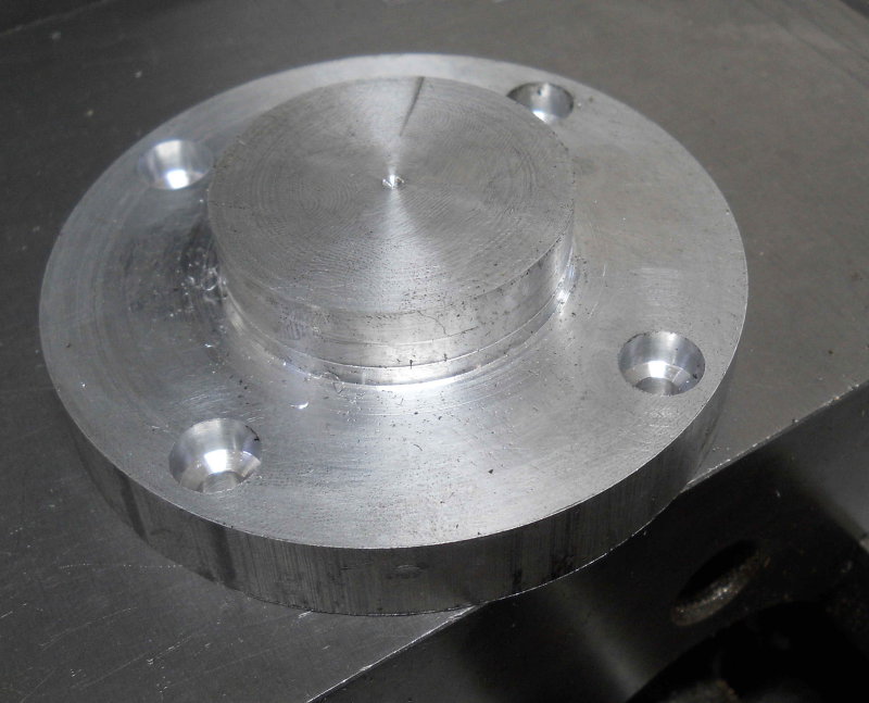
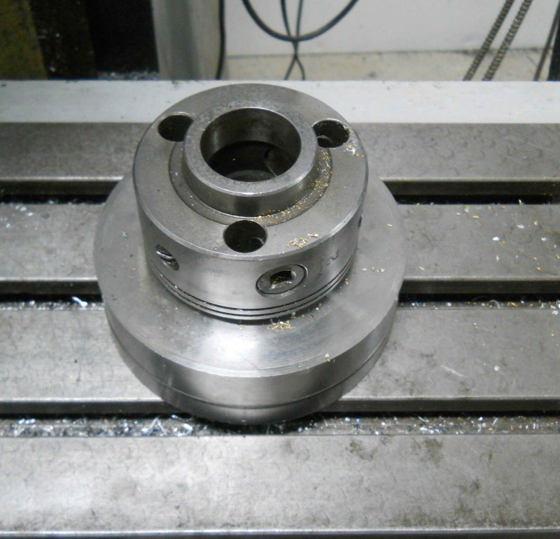
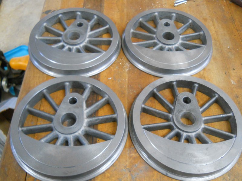
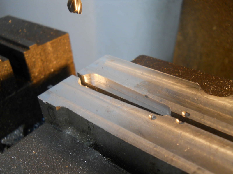
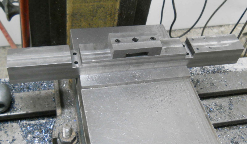
I was advised by a member of another forum that I should be using a faceplate for forming the flange, using a bolt against one of the spokes to prevent the wheel from turning. That sounded perfectly reasonable, except that I don't have a faceplate for my lathe. What I do have is a dog driver that I bought used, and that came with an aluminum fixture place that bolts to it. So my goal for the day was to concoct a way of mounting the drivers on this plate. I first sliced off a 1" thick piece of 3" aluminum rod, then faced it on both sides on the lathe. On one side I formed a spigot and flange. The flange I drilled and counterbored for 4 10-32 screws:

large.jpg


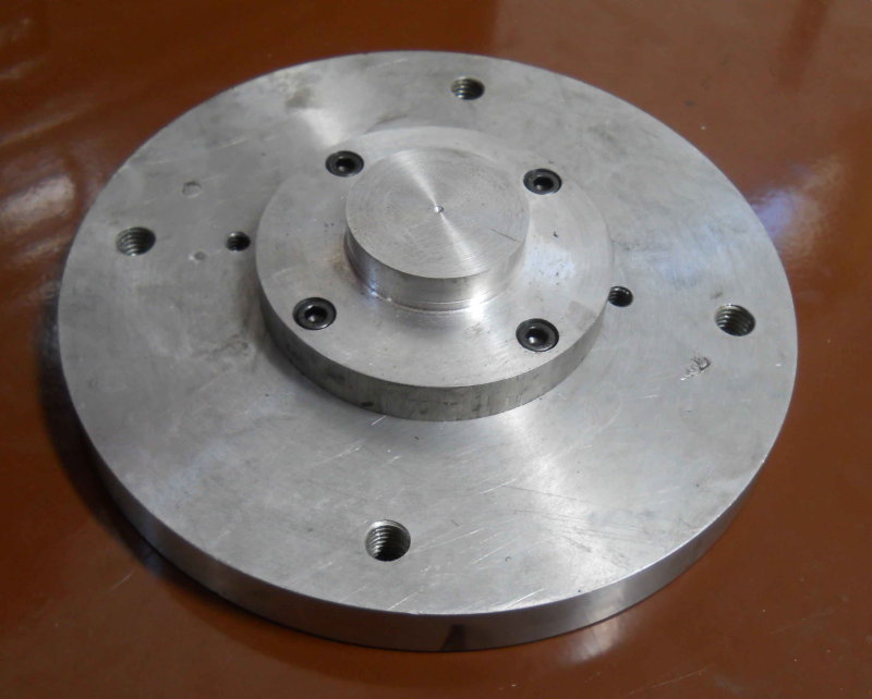
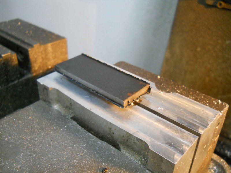
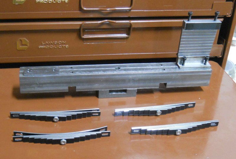
The next step was to drill and tap 4 matching holes in the fixture plate, then screw the two parts together:

large.jpg


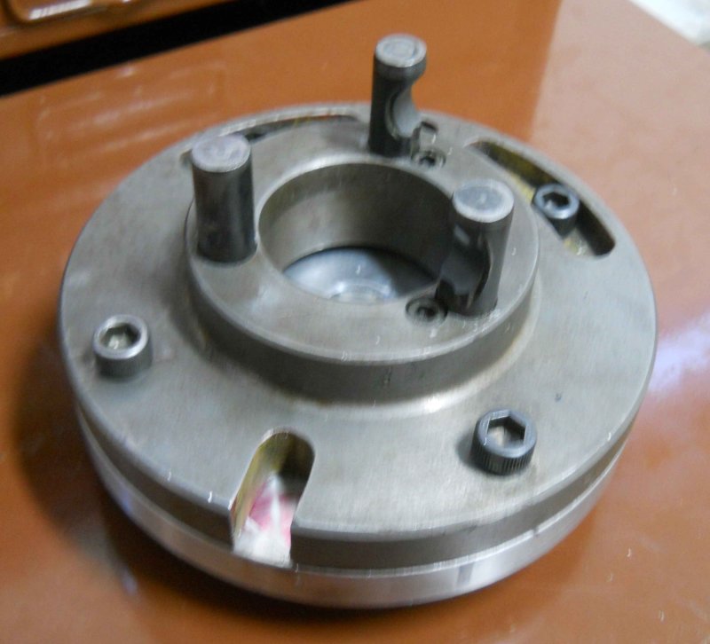
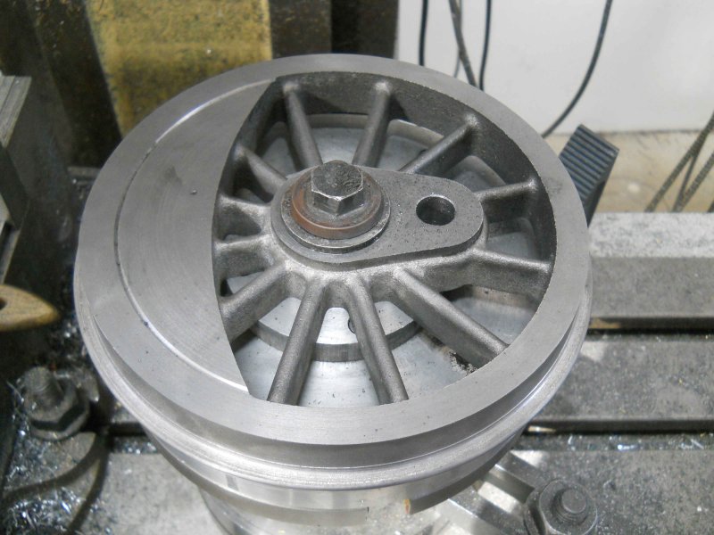
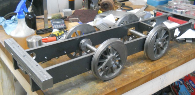
The ensemble is bolted to the dog driver, then mounted on the lathe spindle (D1-3):

large.jpg


I could then turn the spigot down to a sliding fit for the drivers plus drill and tap the center for the mounting screw. By fitting as driver, I could drill and tap for the driver screw, also 10-32.

large.jpg


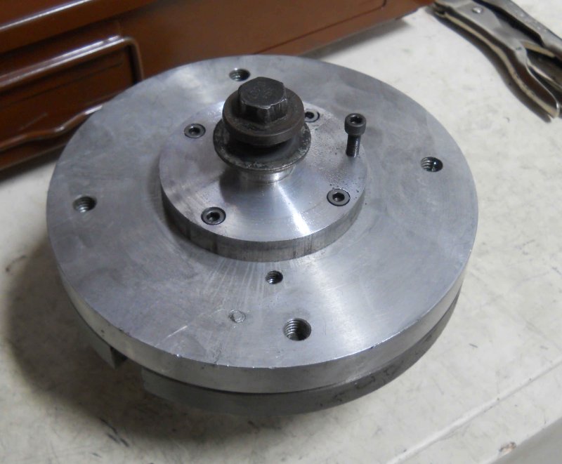
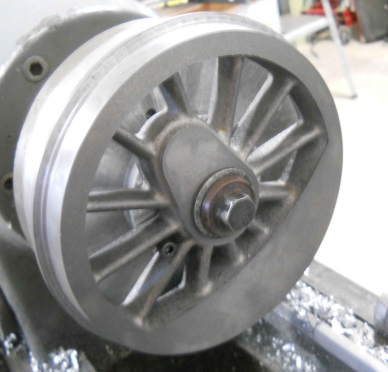
Now with the assembly mounted on the lathe, I could put the drivers securely in place and turn the flanges. This went really well and much faster than for the previous method. I ran the lathe in back gear at 100 rpm, and had very little chatter. I also was able to cut the "paint line" in the counterweight.

large.jpg


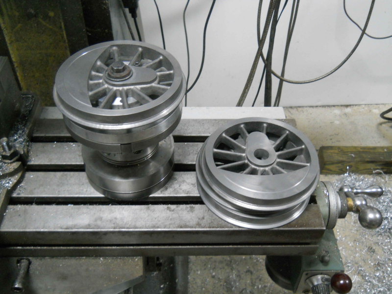
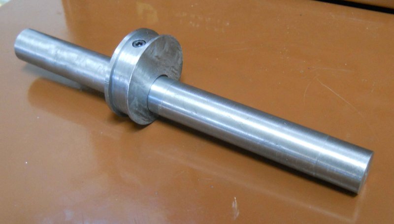
While this fixture took most of the afternoon to concoct, it will be useful for the next step, which is to drill the crankpin holes. I made this D1-3 mill mount some time ago to allow work to be moved from lathe to mill without unchucking:

large.jpg


So with the mount clamped to the mill table, I'll be able to ensure that all four drivers have their pins the same distance from the axle bore. The driver screw will also act to position all 4 at the same angle.

large.jpg


But that's for another day. ;D
 
I finished the drivers by drilling the crankpin holes, using the setup from the previous post.

large.jpg


large.jpg


While doubling Kozo's plans would mean the crankpin is 9/16" diameter, I am using 1/2", as I have a reamer for that size. Shouldn't make a difference.

I made a start on the brake lever links, but was unable to finish yesterday. I'll post pics when they're done.
 
Kvom

This sure is coming along nicely. Watching a 75 buck casting going off all over the place would have tested
my pucker factor...

looking forward to the next installment,

Joe (Who WILL build a loco.... someday...)
 
Thanks for looking in Joe. I think this build is quite a bit easier than the Snow you're doing. It just has bigger and more expensive parts. Other than the boiler, the only parts I'm having a problem visualizing the machining sequence is the brake shoes.

Yesterday and today I worked on the "brake lever links". These parts, two mated on a side, transmit braking force downward, which spreads the ends apart. The ends are attached to the brake levers, which in turn press the brake shoes against the wheels. The profile of each part is the same, so the first step was to CNC mill that profile into some pieces of 1/2" thick CRS. Each part is a bit over 2" long.

large.jpg


Next I mounted aluminum soft jaws on the vise and milled the same profile as a pocket. Note that the jaws are clamped on a thin piece of material while being milled so as to provide some room to actually clamp the piece firmly.

large.jpg


Now each piece can be clamped in the pocket:

large.jpg


And have the "substrate" milled away:

large.jpg


The same pocket is then used to drill each end of each part.

large.jpg


And the final CNC operation is milling the cheek cuts on two of the links:

large.jpg


large.jpg


Then after filing the burrs, I milled the slots on the Bridgeport using a 1/8" carbide endmill. In retrospect, I could have done them faster with less tedium via CNC:

large.jpg


The profile could have been milled manually using angle blocks; the side angle is 3.1 degrees, but CNC makes parts like this a lot easier.
 
The latest installment is machining the brake levers. These parts attach to the lever brackets, lever links, and brake shoes (all shown on p. 213) via pins secured by e-clips. I decided to CNC drill and mill the profiles for all 4 copies in the same operation, using a piece of 12L14 recovered from the school scrap bin. I did spend a fair amount of time in Cad moving the pieces around to fit on the stock with somewhat minimal wastage.

The first operation was to mount aluminum softjaws on the vise, as I would be milling/drilling through holes. I machined a ledge in the jaws to support the work.

large.jpg


Next, the drilling and milling were done. Here the CAM program left holding tabs to keep the parts attached to the stock. The tabs were .1x.1", specified so that they would be removed in the final milling operation.

large.jpg


The profile didn't cut through the material, so I must have miscalculated something; however a facing op on the Bridgeport to remove a few thou from the bottom exposed the part profiles. Then a few minutes work with a hacksaw cutting the tabs left the parts free.

large.jpg


Now I machined the tops of the vise softjaws flat and milled a pocket .120" deep using the profile of the part. Afterwards I found the parts wouldn't fit. It was necessary to rerun the CAM program specifying a negative roughing allowance of .005, which in effect expanded the entire profile by that amount. Now the parts fit securely. Note that for these types of operations the pocket needs to be the mirror image of the part.

large.jpg


Machining the "bottom" of the parts brings them to the correct thickness as well as removing the tabs. Again the CAM program specifies milling wider than the profile to avoid burrs on the edges.

large.jpg


Finished; this material machines a lot nicer than the CRS I used on other parts so far:

large.jpg

 
Keeping this thread on page 1: ;D

Today's part was a pretty quick and easy one once I got into the shop. Again, using CNC with holding tabs to mill out the profile, then filling off the tabs once cut free:

large.jpg


I don't have any 1/8" steel, so anticipating obtaining some I am drawing up all the different spring hangers from p210. I plan to cut all of them from one piece of stock in one CNC run.

Expecting snow and ice today and tomorrow.
 
I got the spring bands done over the past two afternoons, then fitted the stirrups to the axle boxes via a bit of filing.

large.jpg


I've got the spring steel on order, as well as some 3/16 drill rod for the pins. These pins take e-clips, and hopefully the grooving tool I ground last year to cut some model cylinder fins will work on the clip grooves.

As we've been snowbound here in Atlanta for the past few days, I've spent the time drawing the various parts in CAD. So there's no lack of parts to make when I have suitable stock. I think the valve gear and rods will likely be stainless until proven otherwise.
 

Hey kvom,

I missed the last few installments and all I can say is wow!

Great progress on a pretty serious machine. You have made great use of your new shop and schooling and are obviously a fast learner because your work and techniques are looking great.

Well done! :bow:


Coming along nicely. Can't wait to see the springs on there.

Ron
 
Thanks for looking in guys. Spring material is supposed to arrive Friday afternoon, so I might get started on them this weekend. I worked on the hanger brackets this afternoon, but broke my last 1/8" endmill cutting slots in them, so no pics of new parts today.
 
Having been given some 1/8" thick CRS, I determined to make the spring hangers. There are 14 in all of 4 different varieties, including 8 with slots. My goal for today was to make the 6 that lack slots, pending arrival of my delayed Enco shipment with new 1/8" endmills.

Having some 1" wide strip, I cut off 10". To accomodate this on the CNC mill, I milled "parallels" into the soft jaws on both 4" vises; since these were done in a single pass, the vises are automatically trammed to each other. I also don't have to worry about the tools cutting through and striking metal parallels.

large.jpg


One of the 6 didn't work out well, but I did end up with 5 usable hangers. The 6th will be made in the same run as the other 8.

large.jpg


The other task of the day was to drill and tap the mounting holes for the brake lever brackets on the bottom of the side frames.

large.jpg
 
I made some progress the past few days, although not without pain. I was milling the support plate (p112) that attaches the foot board to the running board and broke an endmill from a too-aggressive cut. The piece was also ruined. I went ahead and finished one, but will need to find another suitable piece of steel to remake the other. FWIW, I milled the two pieces as one to avoid the need to SS the two pieces together.

Yesterday I spent the entire afternoon in the shop of a fellow club member and constructor, shooting the breeze and absorbing a lot of RR and knowledge (hopefully some will stick). I had brought over the coil of spring steel, and my friend used his shear to cut all of the pieces for the spring packs to length.

Today I used a 1/8" 4-flute carbide endmill (fresh from Enco) to drill out the center holes in each leaf. I cut the slots in the ends of the top leaves by drilling 3 adjacent holes, then milled them together. Just need to finish the hangers to get the suspension machining finished.

large.jpg


Thanks for looking in Z.

Yesterday I spent machining the two axles. These are just two steel cylinders .874" in diameter and ~8.625" long. My raw material is some nice steel rods that were donated to school and free to me. They are 3' long and 1.25" diameter. My lathe is just an inch or two too short to try to turn both axles together, so it went one at a time.

I noticed problem while turning to diameter, in that there was a taper of about .002-3" over 6", with the diameter getting smaller towards the chuck. So I decided to turn to .880, finish the end near the tailstock, then part off and turn the other end plus the center with the piece chucked in a .875 collet. Theory did not meet with practice; while I measured the diameter at .874, once I fit the axles to the wheels it was obvious that the fit was quite loose. A new measurement showed the end diameter to be .007 too small. Since I plan to fix the drivers to the axles with 620 Loctite, that gap is not a problem. However, it's enough difference to allow the axle to wiggle a bit, meaning that the two drivers might end up not perfectly parallel to each other.

My theory on this relates to the fact that the steel was very hot when removed from the lathe. I believe that it expanded during turning; and since the more massive chuck acts as a heat sink, the end nearer to the chuck stays cooler, hence has a smaller diameter. So I think I'll remake these, first turning to .885, then letting them cool down before finishing to .874 or a sliding fit on the drivers.

Since this type of machining is a bit tedious, I decided to spend today making the eccentric that mounts on the rear axle and drives the water pump. This is made from grey cast iron. The disc is 2.063" in diameter, .625" thick, with the slot for the strap being ,44" wide and a diameter of 1.872. I had a piece of 2.5" diameter CI rod left over from another model build, so it went onto the lathe. Turning and facing were no problem. However, I had a lot of chatter cutting the perimeter groove with a 1/8" wide parting tool. I think the problem was that the piece stuck out too far from the lathe jaws. In any case, I put the lathe in back gear and went in super slow. Then cut off with the bandsaw.

Next, I chucked the disc in the milling vise to mill to thickness and remove the saw cut marks. The interior hole matches the axle diameter and is offset .400", giving a stroke of .800 inches to the pump piston. I drilled out to 13/16 with a succession of drills, bored a further .06, and finished by reaming .875.

The final step was drilling and tapping for a set screw. The 3-3/4 scale engine uses a 5-40; Kozo doesn't give much indication about fastener sizes, so I decided to go with 8-32. The hole from the far side of the axle bore is over 1" deep, and too long for my 8-32 tap to thread through completely. I decided to counterbore the hole for an 8-32 SHCS, but even using a normal set screw it makes sense to counterbore the hole before tapping. With the counterbore, a 1" SHCS fits perfectly. Once the water pump is built and everything is lined up, I'll put a dimple on the axle under the screw to ensure that the disc won't ever slip.

large.jpg


Sorry to hear about the axles Kirk.

You seem to be coming along nicely other wise though.
I keep checking in even if I don't post a lot.

Ron
 
A most "axle-ent" day in the shop as I succeeded in machining the axles to a good slip fit on the drivers. Starting with the 1.25" stock in the 6-jaw chuck, I turned down to the largest 5C collet (1.125), and from there on I was able to use the collet chuck, which is more accurate. l alternated the axles until both had been reduced to 15/16, at which time I broke for lunch and allowed the steel to return to ambient temperature. From there I turned down just 2" from each end to the target diameter of .874. Once I had the first end that had a good fit to the driver bore, I didn't change that measurement on the DRO and turned the other three ends. By taking short, shallow cuts the metal doesn't heat up and expand as it did previously.

While the resultant diameter fit the drivers very well, they were a tight fit to the axle box bores, but by loosening the screws slightly that hold the two halves together I could rotate the axles in the boxes. The eccentric disc didn't fit well at all, and I ended up boring it out and additional .01.

Once all that was done, I couldn't resist doing a test assembly.

large.jpg


It looks as if I have .10" of sideplay on one axle and .07" on the other. I need to shorter the axles to their final length and paint the drivers, and then I can think about quartering. I was happy to see that the axles turn without too much effort when it's all together.
 
kvom said:
It looks as if I have .10" of sideplay on one axle and .07" on the other. I need to shorter the axles to their final length ...........

Before you remove it all, don't you need a bit of side play so it will go around the bends in the track?

Pete
 
Back
Top