Joy's Valve Gear Horizontal Engine

Home Model Engine Machinist Forum

Help Support Home Model Engine Machinist Forum:

This site may earn a commission from merchant affiliate links, including eBay, Amazon, and others.
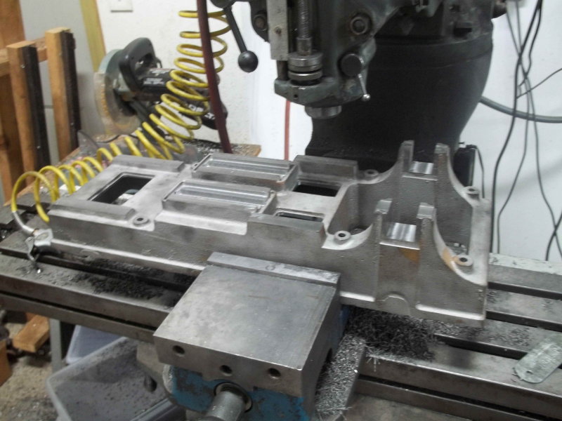
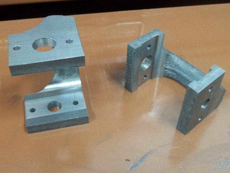
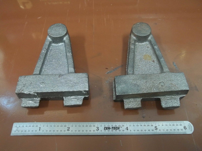
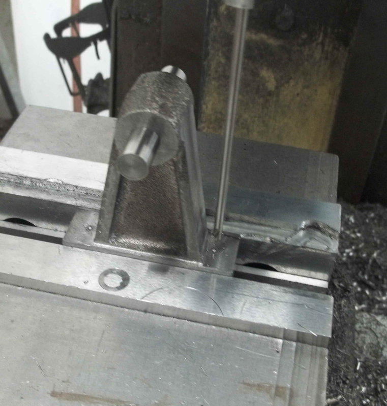
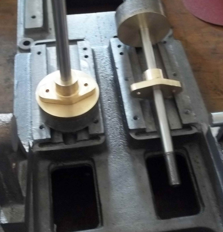
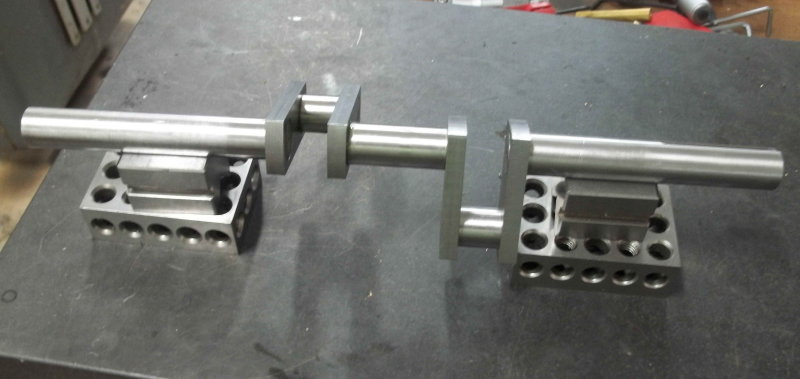
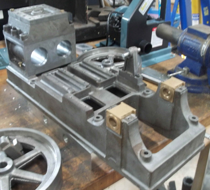
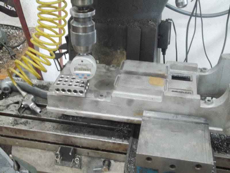
Next I measured the relative heights of the 3 flat surfaces that will have tapped holes. The left side mounts the cylinder; the center has the crosshead guides and valve pedestals, and the right is the top of the main bearings. The unmachined surfaces are quite close to their relative differences per plan, withing .030".

large.jpg


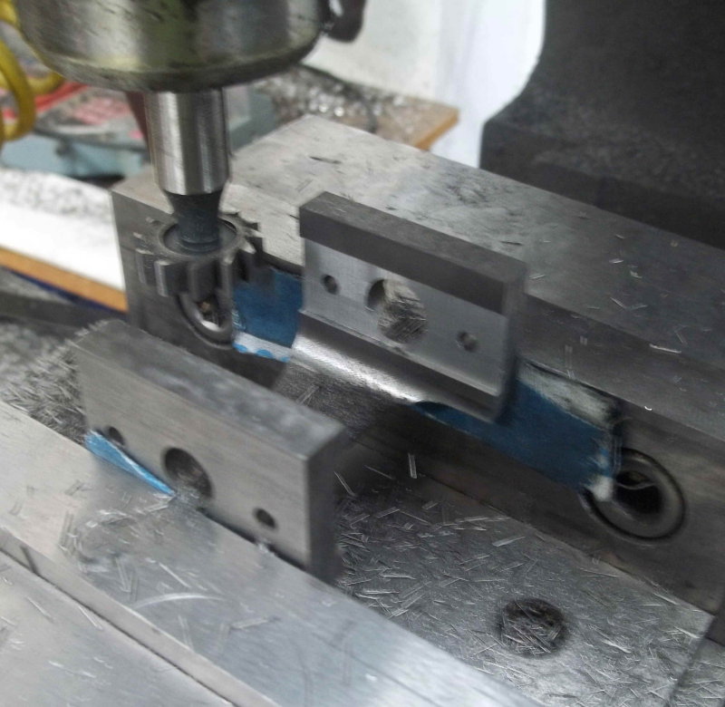
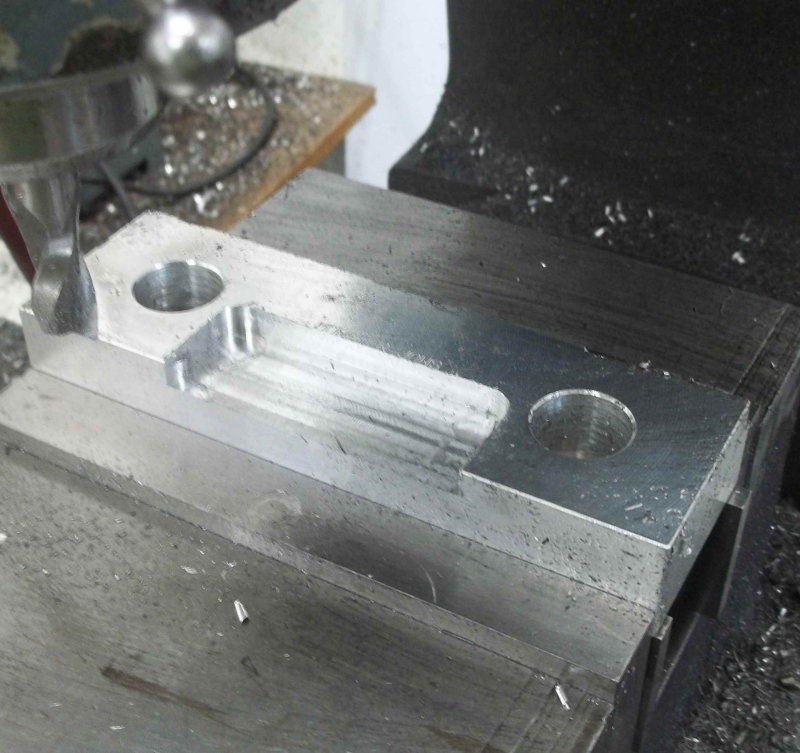
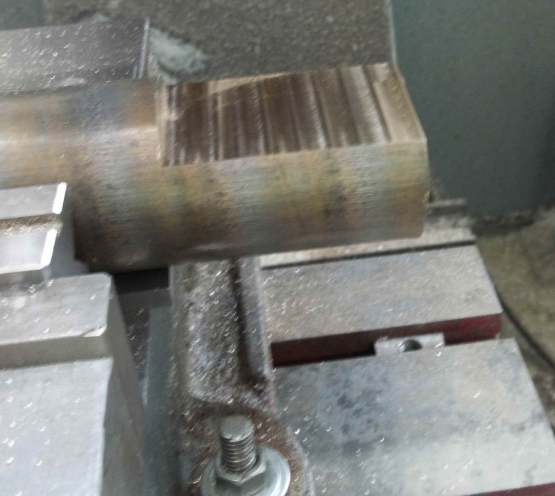
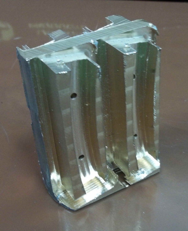
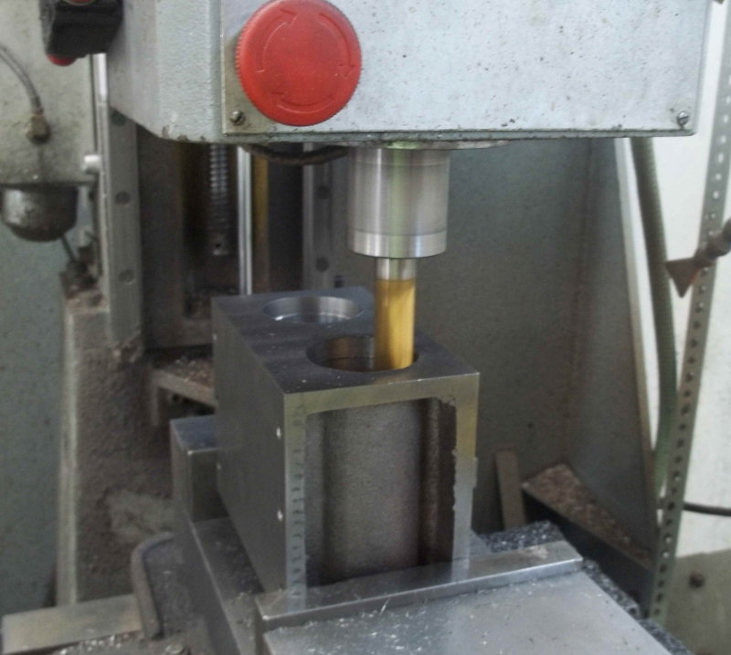
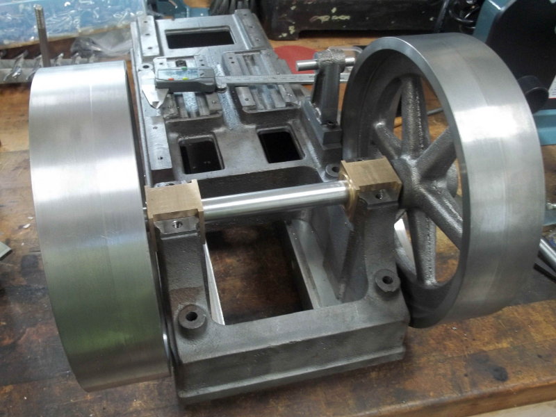
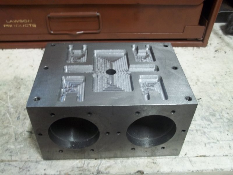
Next I used a small face mill to flatten each of the surfaces, taking the minimum needed. This meant removing only about .020" max. Then machined the faces of the bearing stands and both sides to a depth of 1.40" and keeping the width of the stands at 1.25". I managed to hit the front one pretty dead on, but the back ended up 8 thou thinner. I'll need to make the grooves in the bearings to match.

large.jpg


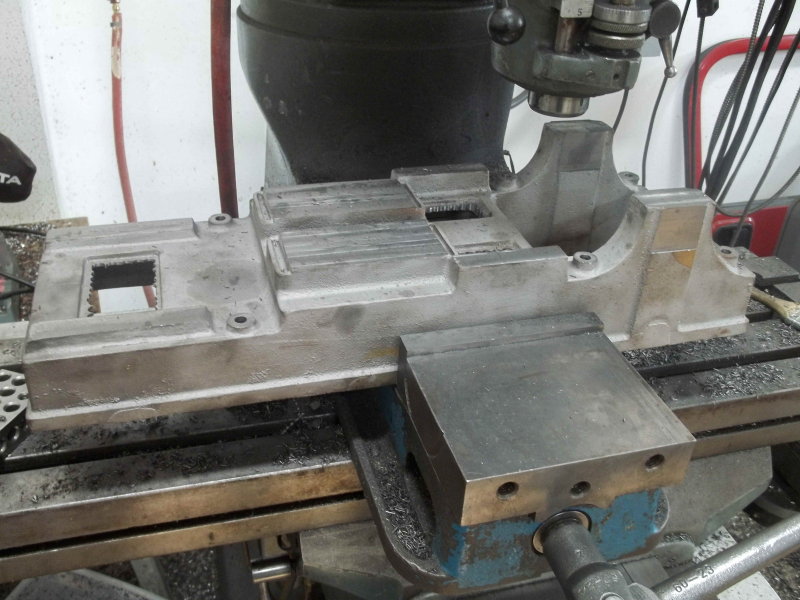
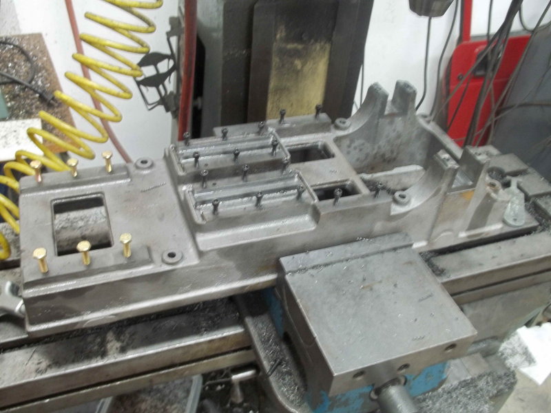
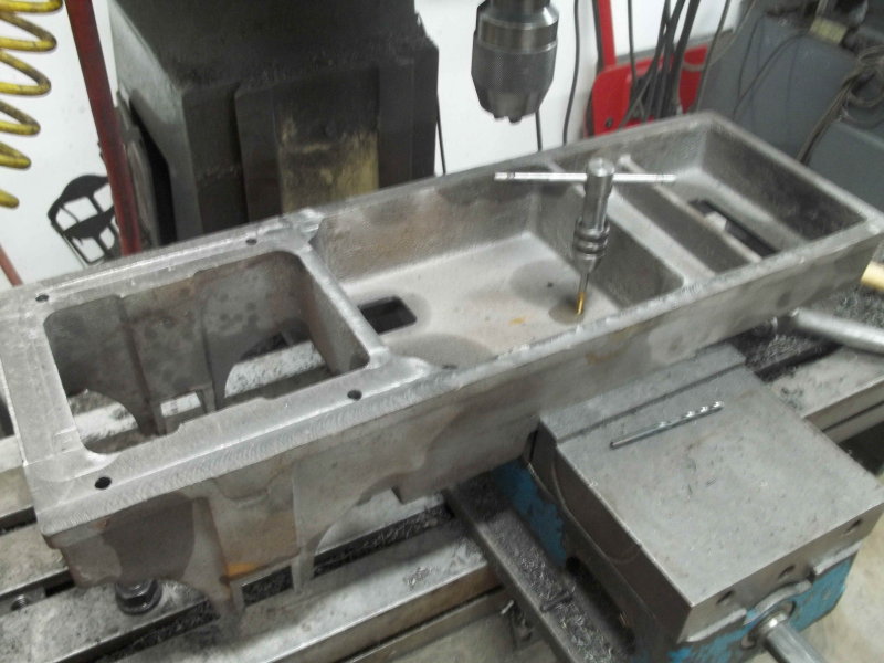
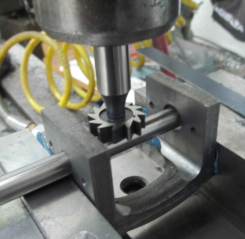
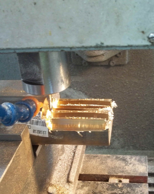
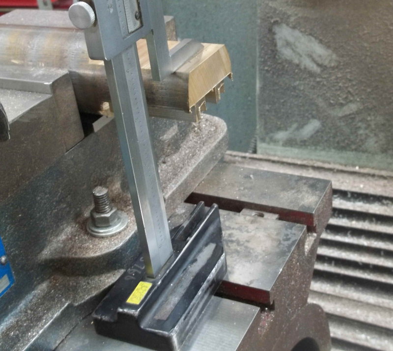
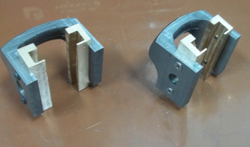
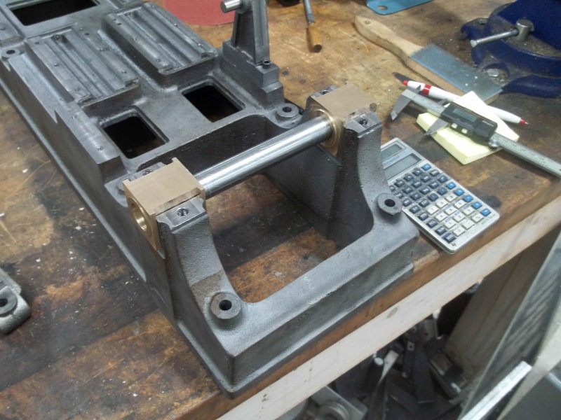
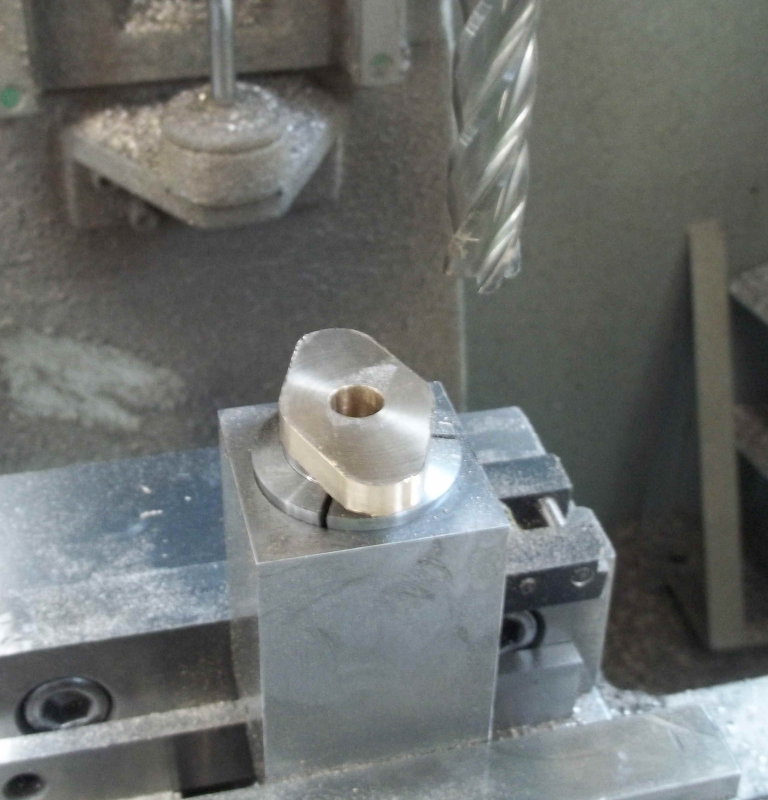
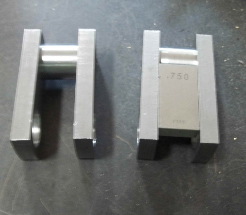
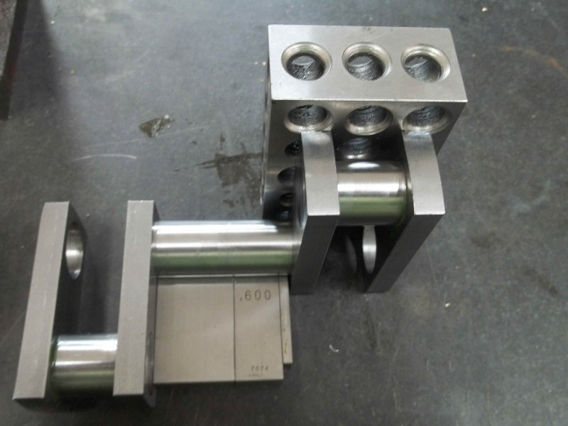
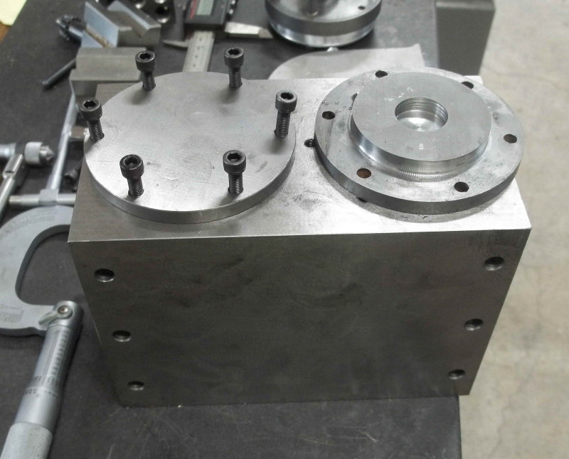
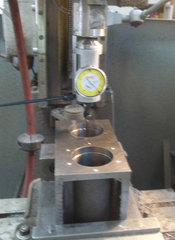
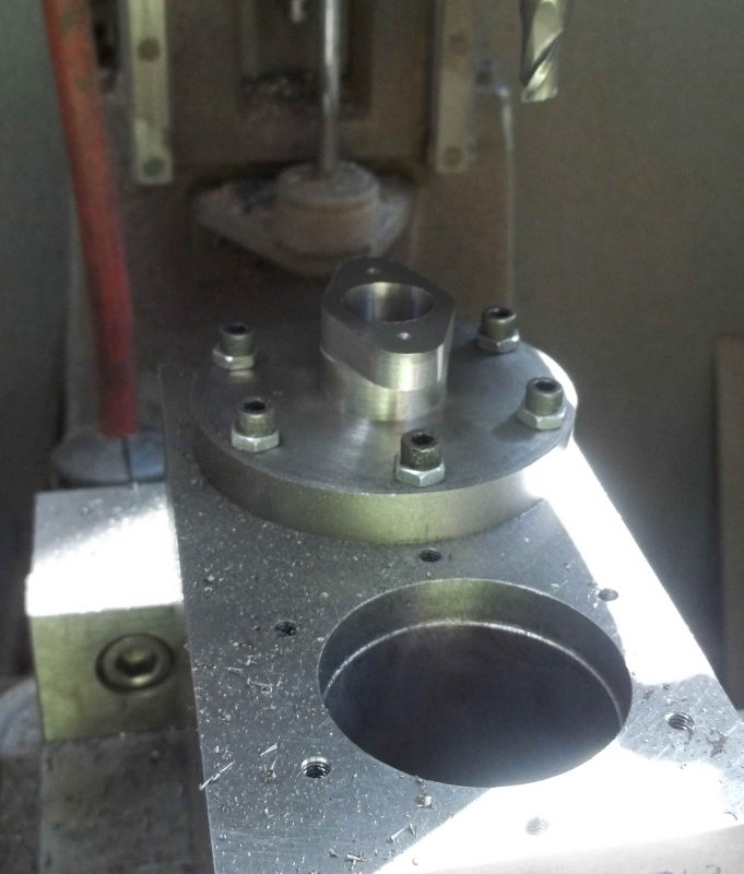
The next major step is machining the openings in the stands for the bearings. Once done, the bottom of the opening becomes the reference datum for facing the other two mounting surfaces. The center of the opening becomes the zero point of the x-axis, and the two outer faces of the stands become the datums for determining the engine centerline. All the mounting holes are positioned using this derived point in the XY plane and should help ensure that all the motion gear is straight and parallel.
 
Lots of cranking the dials today, but the machining on the top of the base casting seems done. Milled the slots for the main bearings, leveled the two other mounting surfaces, machined the slots for the crosshead guide, and cleaned up the three square openings.

Next session will be drilling and tapping the various mounting holes.

large.jpg
 
I finished the work on the base casting a few days ago. Only needed drilling and tapping on the top.

large.jpg


Then reversed using the machined mounting surface. I used a jack screw on one end to shim it level along the length, needing only about 20 thou of machining across the entire surface. Finally just needed to tap the through hole where the radius rod pivot block will be attached.

large.jpg
 
Working on the rocker slide frames the past few sessions - awkward castings. Got all the outer dimensions machined plus the holes for the shafts and rocker mounting screws. Now need to widen the inner opening and mill slots for the rocker slides.

large.jpg
 
Machining the shallow slots used to align the rocker guides in these frames using a 1x1/4" keyseat cutter bought specifically for this job.

With a piece of 3/8" drill rod for guidance, touch off the bottom of the cutter.

large.jpg


Then lower the tool by half the cutter (1/8") plus half the drill rod diameter (3/16) and the slot center will be centered on the hole. Need three passes to cut the 5/8" wide slots on each side.

large.jpg


large.jpg


Then started on the valve journals, two castings:

large.jpg


To be able to hold the casting easier cut out bottom of an aluminum soft jaw,

large.jpg


Clamped upside down using eyeball to position, then trued up the base.

large.jpg


Then holding the base, faced off the bosses on both sides.

large.jpg


Drilled and reamed the boss getting as close to the center of the milled circle as possible by eye and DRO, then trimmed the base to give the center its correct distance from the hole.

large.jpg


Then used the drill rod to find the center in order to drill the clearance holes in the base. Luckily I had a long center drill to be able to reach.

large.jpg


After that I had a disaster and ruined the second casting, so it was time to stop for the day. If I can't get a replacement casting I can machine the matching part from stock.
 
With CNC mill back in operation, I decided to make the slider guides. These are to be made from bearing bronze, which seems to be available only as round stock, not square bars. I have a piece of 2-1/8" round, and verified via CAD that I could make the 4 necessary pieces using that cross section with one 2.5" length. So clamped in the vise and milled a flat on both sides.

large.jpg


Nww Milled the profiles for 2 guides and drilled the mounting holes. Endmill is 3/16" carbide.

large.jpg


Turned the rod 180 degrees for the other two. Used a height gauge to ensure the flat is horizontal.

large.jpg


After milling the second pair, cut off from the parent stock.

large.jpg


Then after some tedious whittling with mill and bandsaw, tapped the mounting holes 6-32 and fit to the frames:

large.jpg


Still need to debur the threaded holes in the slots and shorten the screws.
 
Started on the main bearings this afternoon using the same round bar of 660 bronze. Interesting finding is that the bar measures 2.045" in diameter rather than the 2.125 + 1/32 promised on the Enco site. Looks as if they pulled from the wrong shelf; I sent them an email asking for a credit since the price difference is $26.

Anyway, the 2" bar is just large enough to mill the bearings. First task was to cut off two pieces about 2" long. Glad the bandsaw could do it as a hacksaw would take a long time.

large.jpg


Then faced both sides on the lathe.

large.jpg


Mounted aluminum jaws on the vise on the CNC mill and cut a pocket to hold the work. First op was to drill a 1/2" through hole.

large.jpg


Then spiral milled the hole to 11/16, milled the side profile, and the top boss, all with a 4-flute endmill. Finally reamed to .75".

large.jpg


Then over to the Bridgeport to mill off the bottom to length, then back to the CNC mill to machine the other boss.

large.jpg


Still to do is mill slots on all 4 sides to fit the pedestals on the base. The reamed hole is not a sliding fit for .75" drill rod, so I'll have to polish the rods for the crankshaft, or lap the holes, or both.
 
Installed the main bearings to the base this afternoon. The goal was to have a tight sliding fit with the shaft holes aligned, so lots of sneaking up on the dimensions and ensuring to take the same amount off the slots on either side, keeping the hole centered. I was more than pleased that a test bar of drill rod slides easily into both holes at the same time.

large.jpg


At a future time I'll mill similar slots in the bottoms of the bearings to lower the crankshaft to align with the conrod and piston rod at dead center.
 
Spent a couple of frustrating afternoons in the shop working on the cylinder bores. The problem is that the bore is 4" long, and my longest endmill is capable of 2.5" maximum depth for spiral milling. So I've tried to match it up milling from both ends, and it's ending up a couple of thou off where they meet. The tried the boring head on the Bridgeport; got very bad finish on the first 1/2", plus the VFD shut down from overload -- normally should run this in backgear, but for some reason I can't get the back gear to engage. Then looked to see about using the boring head on the CNC mill, and had clearance issues with both the vise and the table given the current setup. All my efforts have been at a trial diameter of 1.75" vs. the final 2".

So this morning I logged in to McMaster and ordered a .75" 4-flute HSS EM with 4" flute length. G-Wizard shows a deflection of only 1 tenth with axial and DOC engagements of .05", so I expect to get a pretty good milled bore that can be honed afterwards. We shall see.

In the interim I'll start on the built-up crankshaft.
 
Loaded up the big endmill and spiral drilled the cylinder bores to a nominal 2". I discovered that the fore-aft faces of the cylinders are slightly out of square with the top and bottom, so I chucked it in the vise and used a DTI to set the bottom face parallel to the Z axis.

As best as I can measure the bores about .004" smaller at the top with several thou taper towards the bottom. Going to buy an adjustable cylinder hone and see what I can do with the taper. For running on air a clearance of .002" in diameter for the pistons should work according to Dennis Howe.

large.jpg


Cut off more slugs from the 2" bronze rod and roughed out the pistons, then attached them to the piston rods I made earlier. I'll use the rods in the lathe when turning the piston diameters to fit the bore; that way the rods and pistons will remain concentric.

large.jpg


Also started working on the cylinder packing glands but ran out of time to finish.
 
Finished the piston packing gland this afternoon - quite simple parts from bearing bronze. First ops were milling the spigot that goes into the cylinder cover, then facing to length and drilling/reaming the center hole.

large.jpg


Now hold the spigot in a square collet block and use the CNC mill to profile the flange and drill the mounting holes.

large.jpg


All done, shown with the piston and rods:

large.jpg


The valve packing gland is the same but a bit smaller, and the same process.
 
Made a start on the crankshaft, which is held together with Loctite 620. Used the gauge block to control spacing, and the surface plate to align. I probably should have used another piece of rod for alignment. Guess I'll see later if I need to press the pieces apart and reassemble.

large.jpg
 
Continuing to build up the crankshaft. Here's the setup to connect the two crank portions. Calculated the gauge blocks needed so that the cranks are 3.125" apart center to center.

large.jpg


Afterwards checked for a fit and found that the total width of the cranks is a few thou too large to fit between the bearings. So I'll have to sand/or file a bit once the crankshaft is complete. In the meantime cut material to make the two ends of the shaft and got them to fit the bearings. When I reamed the flywheels I got a sliding fit on 3/4 drill rod. But the bearings and crank web holes were too tight, so I had to reduce the diameter with several grades of sandpaper on the lathe. After fitting to the bearings I mounted the flywheels for a beauty pose.

large.jpg
 
Cut the end pieces of the crankshaft to size and dry assembled as shown here:

large.jpg


Used a DI to measure deflection of the ends as I rotated it on the V blocks. 0 on one end and a max of 2.5 thou on the other. Not too bad a difference over 14". I haven't glued the end pieces yet as they need slots milled for the keys. I'm going to wait until I get the keys in hand to see exactly how deep the slots should be.

Rented a cylinder hone to apply to the bores. Still having a bit of difficulty getting accurate repeatable measurements of the bores with the equipment I have. I want to mill the relief diameter at the rear end in order to make it easier to determine how much taper, if any exists. Might get an expanding reamer if need be.
 
Some slow progress over the past two shop sessions. Machined the outer radius of the cylinders for the back side plus drilled and tapped the mounting holes for the rear cylinder covers. The small occlusion in the casting doesn't appear to be a problem as it doesn't extend into the part of the bore where the piston rides. Then it was time to fit the rear covers.

First task was to cut a 1/4" deep pocket .75" in diameter on the inside face. This is needed since the piston rod extends a bit beyond the rear face of the piston. Mounted the covers on the lathe and use a 1/2" center cutting endmill to go in .25", then expanded the diameter with a tiny boring bar,

large.jpg


I also needed to dismount and mount the covers several times to fit the inner boss to the cylinder bore. Here's a technique I find useful in getting thin discs straight on the 6-jaw chuck. Place parallels as shown and hold the work against them while tightening. Then don't forget to remove the parallels before turning on the spindle. FYI, this Cushman chuck is original to the lathe, both 1942 vintage.

large.jpg


The end result with the covers. Need some nice 10-32 fasteners eventually.

large.jpg


The front covers will need some more precise work, so decided to drill and tap the holes for mounting the steam chest. After using the surface plate to align the front faces of the parts and clamping them in place, I used a transfer punch to mark the cylinder block. This was necessary since the holes in the steam chest bosses were centered on the bosses by eye, not a precise coordinates.

large.jpg


At the end of the day, put the cylinder assembly onto the base for a poser shot.

large.jpg
 
Another fiddly day in the shop, working on the front cylinder covers. Here I need to try to be more precise so that the holes in the cover and gland are as close to the center of the bore as possible. First need to drill and tap the mounting holes for the covers. Mounted on the CNC mill and finding the bore center. Pretty much using the max Z space here.

large.jpg


I could then spot drill for the holes using a collet, but no room for a chuck. So back to the Bridgeport for drilling and tapping. That spring loaded tap follower is a handy gadget.

large.jpg


Now back to the CNC mill for more center finding, then screwed a cover onto the cylinder. Now I could mill the profile of the cover's flange to match the gland, and also mill the center pocket to match the flange. Finally spot drilled the holes for securing the gland.

large.jpg


Finally, back to the BP to drill and tap the gland mounting holes.

large.jpg


Still to be done is drill and ream the .376" hole down the center of the cover, and hope it's in the center of the bore. Afterwards I'll still need to turn the boss on the bottom to match the bore, plus reduce the outer diameter slightly sp that both covers can be mounted.

And then the same profess again on the other. I've marked the cover and gland so that I'll always use it on the same bore, in case there's some variation between the two sides.
 
After 3 weeks away and 4 days of jet lag, I ventured back into the shop to do a little work. Machined the top cavities on the cylinder block using the CNC mill. This is the last major job on this casting other than trying to hone the bored straight and drilling the steam passages.

large.jpg


Before I left on the trip I turned one piston down to fit the smaller end of one bore, and found that there is too much of a gap at the wider end. Loops like about 10 thou vs. the 2 thou allowance recommended. Won't try to turn another piston until I can get the taper out or else find that the extra gap won't cause enough blowby to matter running on air.
 
A bit more progress this week.

- Got a friend to broach keyways in the flywheel bores, so was able to mount the crankshaft, bearings, and a flywheel on the base. The gib key isn't very tight, so for the other side I'll reduce the slot depth on the shaft a bit.

- made the slide way tops, slides, and crossheads. Might have been a little lucky but the first piston rod lined up with the crosshead and screwed right in, allowing the crosshead and piston to slide pretty easily the full extant of the slideway. Muncaster's version used a split bushing in the crosshead, but here a simpler bronze bearing will support the small end of the conrod. Still have to machine the boss around the hold that connects the piston rod, plus drill an oiling hole in the top through the bearing.

large.jpg
 
Spent a couple of hours at the CNC mill doing the first set of operations to carve the valve journals out of a piece of 3x7x.75" CRS:

large.jpg


I did get castings for these and got one machined, then messed up the second. Got a replacement casting that had mismatched halves and wouldn't have looked enough like the first. Hence, machining them from bar. They won't be as thick as the castings so I'll need some spacers on the valve shafts.

Next will turn over to machine the opposite sides to match, then cut out of the matrix and finish on the Bridgeport. Might let it run in the vibratory finisher for a while to get a matt finish.
 

Latest posts

Back
Top