Joy's Valve Gear Horizontal Engine

Home Model Engine Machinist Forum

Help Support Home Model Engine Machinist Forum:

This site may earn a commission from merchant affiliate links, including eBay, Amazon, and others.
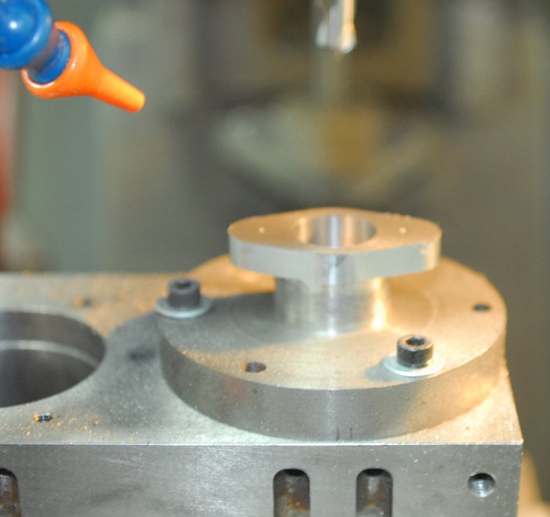
After hearing that the .012" cylinder taper wasn't going to cut it I spent the afternoon playing with this impressive combination:

large.jpg


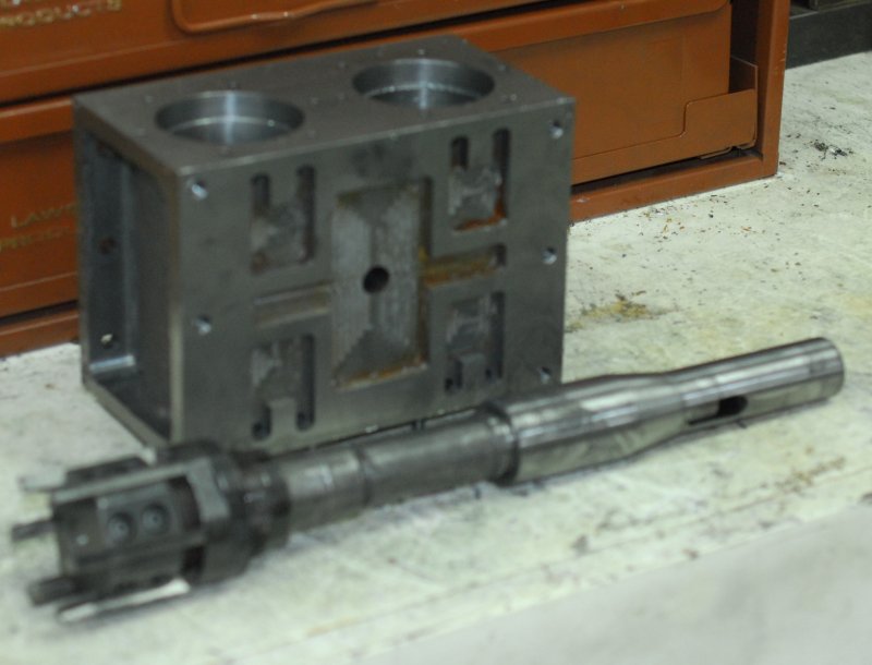
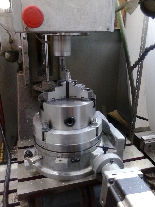
Expanding 2" reamer with a MT3 shank hooked to a MT3/R8 adapter for the Bridgeport. Don't try this on your mini-mill. Found the reamer on eBay some time ago and got the adapter from Shars.

The cylinder didn't like heavy cuts with this, and I probably adjusted it 10 times before I got it done. The bore surface is only mediocre, but I'll run a cylinder hone through it later on. At least bore mic measures the same at both ends.

I did just one bore, so I'll have the same process to do for the other.
 
Spent today to work on the last unfinished casting, the cylinder cover that I had rough machined long ago. I mounted the cylinder in the CNC mill and located the center of the bore, the attached the cover with screws. Milled the profile and the pocket for the gland, plus spot drilled the positions for the gland mounting holes and the piston rod.

large.jpg


Then over to the Bridgeport for drilling and tapping. Test fit of the gland:

large.jpg


Then some fettling on the assembly with the piston rods in order to get the rods to move smoothly. Tightening the gland screws unevenly can cause binding on the rods.

large.jpg


The bases of the two covers are slightly different thickness, so I'll plan to face off the thicker one in the future.

After I use the big reamer on the other bore and remake both pistons, all the parts needed for the engine to run will be able to be assembled. I ordered some teflon film to try out as gasket material. Before trying to run it I want to try to eliminate as much friction as possible. The conrod bearing are a too tight to the crankshaft webs, and I need to drill oil holes for them as well as for the main bearings and possibly the crosshead. The lower valve links will be thinned as they're a bit too close to the uppers.
 
Another afternoon of fettling. I took about .02" off the flanges of both the conrod and main bearings to reduce friction, and then drilled oil holes for those bearings plus the crossheads. The conrod big ends required a bit of thinking to get a secure mount for drilling, but I eventually came up with this:

large.jpg


For the big ends and crosshead, the plans call for a .062" hole, while the hole for the much larger main bearings is not dimensioned. I did drill these the same, but it would be fairly easy to increase the diameter when needed. In any case, I intend to add oil cups to all 6 such oiling points, and these will require further drilling and tapping once I know the thread size.

I know there are many here who make their own cups, but the prices for ones from PMR and AME are so inexpensive it doesn't make sense to me to make them. I'll decide at Camin Fever which way to go, and in the meantime just squirt oil down the holes directly.

I did find that one of the wedges for the conrod bearing is too small to press the bearing halves closed. Not sure whether to shim it or make a new one, but in any case I ran out of time to drill the second conrod. With the one conrod reinstalled with the crankshaft and main bearings, there's considerably less friction turning it than before.

One thing to keep in mind is that when drilling through bearing caps and then into the bearing is to mark the caps. That way they will be replaced in the correct orientation if they need to be removed.
 
Reamed the other cylinder bore with the expandable reamer and also faced down the oversize cylinder cover. Also cut off two more slices of the 3" 6061 round, which I'll turn into new pistons to fit the bores.

My gasket material is held up at UPS because of this week's bad weather, but when they arrive and I've made the pistons, it will be time to assemble and put some air to it.
 
And we have a runner!

For at least 2 minutes anyway.

Having gotten delivery of a 1' square piece of .020" PTFE, I devised a way to clamp it flat on some aluminum and cut gaskets using a very sharp-pointed 60 degree carbide chamfer bit on the CNC mill. Tow for the valve guides:

large.jpg


And four for the cylinder covers:

large.jpg


Buttoned everything up after some additional fettling:

large.jpg


And applied some compressed air. The engine was still a bit stiff so gave the flywheel a bit of assistance and it struggled to life. With high pressure it continued to run faster than I would have liked, but cutting down the air caused it to stop. I figured it just needed some run-in time, plus there was no sealant on either side of the valve plate where air was leaking as well as the steam chest cover.

I was just about to stop and set up for a video when the engine jammed up tight. Couldn't turn one flywheel at all, and the other turned slightly because the crankshaft had worked loose on the center bar:

large.jpg


I had been relying on Loctite to keep things aligned, but apparently there's enough force at work to loosen the seal when things won't move. Started disassembly to find that one of the piston rods was stuck tight. After a more complete disassembly I found evidence of rubbing on one side of the aluminum piston and some scoring on one side of the piston rod. I checked the rod against the surface plate and it's not bent.

Seems the jam occurred between the rod and the bronze gland at the position nearest the crank. I believe the bore is just very slightly off from the cylinder head, so the rod was rubbing on the head, and the crosshead seems to be rubbing on one side of its guides.

So after repairing the crank, I'll make a new rod and try to relieve any rubbing between it, the cover, and the gland. Before another run, I'll also make some gaskets for the steam chest.
 
I ordered another stick of 3/4" drill rod to finish rebuilding the crankshaft, so while waiting for it to arrive I made my version of the reversing hand wheel:

large.jpg


Eventually there will be an acorn nut in the center, and the handle could use a bit of a taper for esthetics.
 
So now it's running 'OK', although noisy with the high air pressure needed. It will need some fettling and running in to work on lower pressures and speed.

[ame]https://www.youtube.com/watch?v=eY7jhkFV3Do&feature=youtu.be[/ame]

There's a sticky spot when the #2 piston (further from reversing wheel) is fully back towards the crank. That's why it failed to self-start in the video. Quite airtight with gaskets in place. I used RTV between the valve plate and cylinder block, and teflon film elsewhere.

The engine will be in Maury's booth at Cabin Fever if anyone wants to see it in person. I will probably not do a major disassembly between now and the show, but will try to locate the sticky spot. For the previous problem I ended up taking about .030" off the base of the #1 crosshead and the same off the matching crosshead bar, allowing the crosshead to move outward that amount to align the piston rod better.

I still need to machine keepers for the ends of the conrods and replace a number of screws with studs and nuts.

The reversing lever was installed horizontally with the slides vertical, but that prevents it from being able to tilt back enough to reverse the engine. To fix that I'll need to pin the lever more upward facing at neutral. I may try using a longer piece of threaded rod in the meantime; will look awkward, but possibly can work.

After the shows it will be time to install oil cups, paint, and build a better base.
 
That is an impressive engine! I'm not much of a steam guy (although I do plan to build at least 1 someday) but this is an excellent model. Sounds like it's ready to do real work too.

Congrats on getting it running.
 
Bit more shop time this morning on the engine. By disconnecting the conrod from the #2 crosshead, I determined that the crosshead and/or piston was the cause of the sticky part of the motion. An examination of the piston showed some scrape marks on the crank end, so first action was to file and polish a bit on that portion. Then I noticed that with the piston rod attached there was some binding on the side of one top bar, so I took about .015" off both the crosshead base and the bar. Finally, I noticed that the crosshead base was protruding slight above the engine base, meaning that the crosshead would rub against the bottom of the bars. I decided to shim the bars up by using washers around the mounting holes. The washers measure .017 thick, and doing so freed up the motion quite a bit. After reassembly I made a second video.

Self-start still requires quite a bit of pressure, but once in motion I can throttle down quite a bit.

[ame]https://www.youtube.com/watch?v=VYa-qSQ28dE&feature=youtu.be[/ame]

Seems to be running about 60 rpm. Any slower it eventually stops.
 
Spent the last two shop sessions making studs to replace the screws of the main cylinder heads and the crosshead guide bars. As before, studs are made with 3/16" diameter drill rod with 10-32x1/4" threads on either end. Only a few socket-head screws left to replace after Cabin Fever.
 
After touring the engine to both Cabin Fever and NAMES, and with a week or so to get back into the shop, I started on some of the unfinished tasks.

First was to machine a "keeper" block that seals off the end of the conrod. It's just a steel block with a groove to clear the wedge, but needs a tight fit to the rod. Hence a fair amount of fettling. Then I removed the #1 conrod to drill and tap for an oil cup I bought at CF.

large.jpg


With the rod removed, I found that the sticky spot in the motion is definitely in the #1 side and seemed to be coming from the crosshead guide bars. Since I had an oil cup to install on the crosshead, I did some relieving on the bars as well. Then put it all back together and fired up again on air. It still needs about 40 psi to self start but afterwards it will run nicely at 20. Below that it grinds to a halt.

large.jpg


Side 1 took most of the day, so I expect the same the next time for side 2. I have larger drip oilers for the main bearings but no tap (1/4-40) at present. I could have bought the tap for $10 at CF but cheaped out. I can thread mill the holes but that sounds like a lot of work vs. 10 bucks.
 
I've been playing with getting the 4th axis set up on the mill, as well as family matters, but today decided to do a bit on the engine. Goal today was to make the studs that connect the conrods to the crosshead. I had made one earlier but mis-measured so that it was too long, and for the other I'd just used a 3/8" bolt and nut at CF.

After measuring properly, I decided to use the 4th axis horizontally to hold the stock for thread milling each end:

large.jpg


Installed on the engine:

large.jpg


Other than cosmetics, the main task remaining is to orient the reversing arm so that there's enough travel to actually make the engine reverse. To maintain the arm on its shaft at the correct angle, I'm going to broach a key slot in the arm using the small broach I bought at the CF auction. The broach is 1/8" wide but the cutting teeth are only 1/16", so that will be the width of the slot. I don't have a bushing for the broach and could have made one, must found a 3/8" bushing on Enco for less than $10. When it arrives next week I'll have to see what shims I'll need with it.
 
After some analysis using my SolidWorks model of the engine, I decided that I could modify the geometry of the reversing mechanism by a modest extensions of the threaded shaft to enable the engine to run in reverse. To validate this, I replaced the existing shaft and handwheel with a long piece of threaded rod and moved the mechanism to approximately the same ange backwards as for the forward speed. With this setup I applied air, and the engine ran very well.

large.jpg


Then it was a simple matter to mark the rod for enough room to add the handwheel and its jam nut.

The remaining tasks for the day were to drill and tap the main bearing caps (1/4-40 thread), and mount the PMR drip oilers I bought at Cabin Fever. In addition I whittled down a piece of CRS to make the keeper for the end of the #2 conrod.

large.jpg


All the rest of the work needed to mark this complete can be done with the engine completely disassembled and ready for paint.
 
Really some great engineering on the engine!
gbritnell
 
I've been away from home for a while, but now back at it. I disassembled the engine in prep for paint, and while considering options there I made a start on getting my base ready to attach. The base itself it a piece of black walnut 1.7" thick that I had made by a furniture maker near York while I was at Cabin Fever. I positioned the engine base as accurately as I could and used a transfer punch to mark the holes. After drilling the wood, I decided to still use the aluminum feet underneath, since without them it's difficult to get a grip to lift it. I cut some 5/16" drill rod to length for the studs, but I will wait to mill the threads when the current setup on the mill is broken down.

large.jpg


Today, I started filing the join lines on the flywheel spokes and the main bearing caps preparatory to paint.
 
Masked the castings and sprayed primer on the parts to be painted. I had decided to use an automotive epoxy paint hence gray epoxy primer. The paint is copper colored with a very small metal flake accent. Not exactly 19th century, but the Victorians did like bling paint jobs on their engines.

Still deciding whether to paint the flywheel spokes the same color or something different.
 
Pics of parts after masking and priming:

large.jpg


large.jpg


Setup for the air brush, using CO2 as propellant. No chance of water getting into the paint. The regulator is set for 30 PSI.

large.jpg


Here's the paint system I'm using. Enough for many models:

large.jpg


First I did the smaller parts. Having them on the stand makes spraying all over easier.

large.jpg


Did two coats 15 minutes apart. I plan a 3rd coat tomorrow, plus do the other side of the cylinder. Then attack the base later. This amount of parts used two oz. of paint and a half oz. each of the activator and thinner.
 
Read the label carefully- I once painted a model with rustoleum. It had a nice finish, but I decided one more coat might be good. That turned the whole thing into wrinkle finish. And it was hard as a bear to sand. I never did get as good a finish.

the label warns to recoat within 24 hours or wait 7 days before recoat. Should have read that first.
 
Back
Top