Joy's Valve Gear Horizontal Engine

Home Model Engine Machinist Forum

Help Support Home Model Engine Machinist Forum:

This site may earn a commission from merchant affiliate links, including eBay, Amazon, and others.
Spent a number of hours in the shop working on the lower valve links. I still need to do the side profile on these, but here they are with the rest of the valve linkage pinned together:

large.jpg
 
Finished profiling the lower valve links today:

large.jpg


Then made an attempt to machine the "sliders", analogous to die blocks in other valve systems. Although I used a negative roughing clearance that appeared to make them fit the rocker slides, they are a few thou too tight. I'll see if I can file/sand the outer radius enough to have them fit and slide smoothly, it may be easier just to start them over.

large.jpg
 
Since the engine, even in a partially assembled state, is getting too heavy to lift easiy, I decided it would be a good idea to strip it down to the base, and drill and tap the side hole for the lower reverser mount. At the same time I could attach the bracket that supports the radius arms to the inside of the base casting.

large.jpg
 
Finished my Solidworks model of the engine, not to generate any drawings or CAM files but mainly as a learning tool for SW. I skipped several parts not needed to check the motion.

joy engine.jpg
 
I had to remake the lower valve links for a 3rd time, having misread the plans the second time. Rather than my original plan of a threaded pin to attach to the conrod, I went with a press fit. One side of the hole was reamed .189 and the other .187 (I have a set of over/under reamers) so that the pins were pressed in one side only via vise jaws. The pins were made to match the width of the links (.625") rather than .937 as on the drawing; seems an error on the plan since the upper links need to pivot over the lowers. Here are the upper/lower/conrods shown in place.

large.jpg


I need to shorten the mounting screws for the slider guides, and then I should be able to see the complete valve motion.
 
After shortening the mounting screws for the slider guides and making the pins to connect the sliders and the upper valve link, it was time to see how the mechanism would work. The first issue came up right away as it was obvious that one of the upper links was leaning to one side. Found out that the lower pin that joins to the lower link was drilled at an angle, so that link will need to be remade.

The other link was connected to the sliders:

large.jpg


I found that they would slide well on the forward part of the conrod stroke (toward the cylinder), but not on the reverse. Closer examination shows the sliders contacting the "shoulder" of the link:

large.jpg


The position of that shoulder is not dimensioned on the drawing, and I had made a guess., apparently wrong. My plan is to whittle it down until the sliders clear, then make two new links with the measured distance.
 
Slight progress today. Made a rough version of the reversing screw along with its brackets as can be see in this view:

large.jpg


Being able to lock the slides at a fixed angle frees up a hand or adjusting the rest of the mechanism. I discovered that if the assembly tilts too far forward then the slides will come out of the guides. The position shown allows the center of the slides to just reach the end of the guides as is as far forward as should be allowed. Since there is more thread below the lever it seems a stop should be installed. Until I have valves and the rest of the mechanism assembled, I'll not know how far the the maximum would be in either forward or reverse.

The slides shouldn't hit the upper link. I did move the shoulders 1/3" lower, but then realized that I hadn't installed spacers between the link and the sliders on either side. These keep the sliders apart and inside the grooves of the guides. This picture shows where these spacers (about 1/8" thick in this case) should go:

large.jpg


I also discovered that the space between the guides is about .020" too narrow (the other side is better). While it doesn't inhibit the mechanism is means that the pin that will connect the upper link to the valve link rod will be too wide as currently made. Machining the frame is impractical at the point, so I may just to a combination of narrowing the sliders on this side as well as the taking a bit off the top of the valve link, I may also try to make the pins a bit shorter and use thinner nuts.
 
Spent the last two shop sessions making the slide valves. The plans call for either bronze or CI, and since I had a suitable chunk of 2.5" diameter Durabar from a previous project, that was the choice. After cutting it in two, facing both ends on the lathe, and milling the sides, I ended up with two 2" square chunks. Second session I machines the sides down to the target dimensions of 1.6x1.5", one .82" thick, the other .86. In reality the overall dimensions are not critical.

large.jpg


More swarf than workpiece at this point.

large.jpg


I then used the surface grinder to grind the bottom face that will slide on the valve plate, and then machined the exhaust pocket into the ground surface. Pocket depth is .188" using a 1/8" 4-flute carbide EM. An advantage of CI is that there is no burr and edges remain sharp, which is a goal with these valves.

large.jpg


Then back to the Bridgeport to finish the top portion.

large.jpg


Photo of the cross slots was unfocused, so I'll show that on the next post.
 
Spent some time making the 2 anchor nuts that connect the valves to the valve rods. Simple 1/2x1/2x1/4 steel with a 1/4-28 hole through the center. Main fiddling was milling the thickness to have a snug sliding fit in the slots.

large.jpg


Still need to experiment on the best way to add the crosspiece to the end of the rods.
 
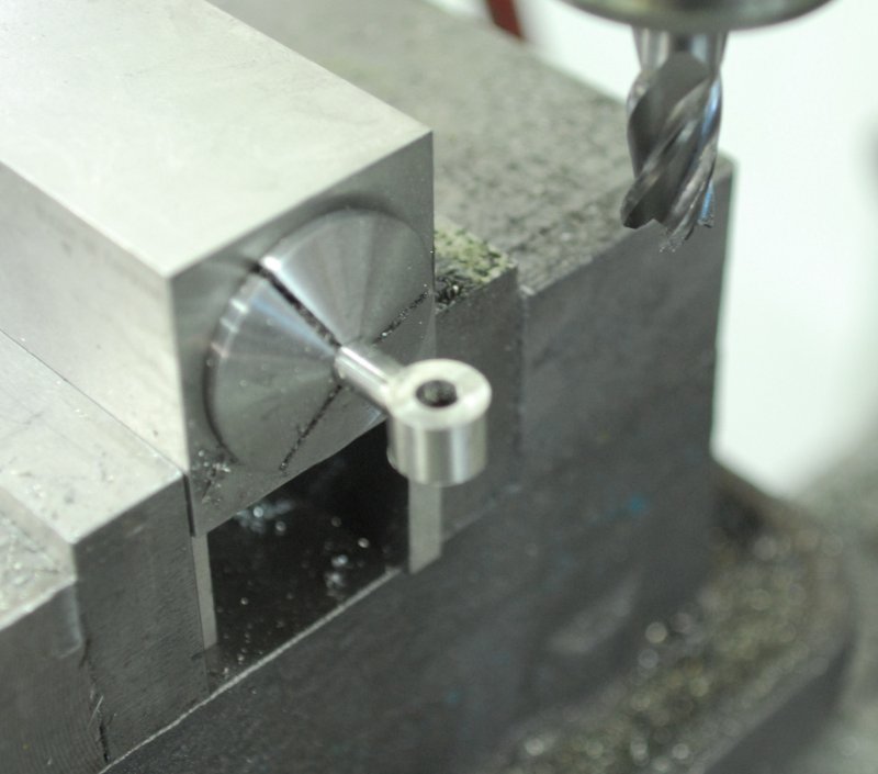
After receiving a shipment of model scale nuts from AME in Fl, I discovered the 10-32 nuts wouldn't screw onto the pins I made for the valve linkage, Seems the nuts I used for testing the thread milling code were loose threads. So I did the mill setup to cut deeper threads. With the setup for thread milling, and having enough 1/4" drill rod, I spent a number of hours working on studs. I need 12 for the steam chest cover, 6 for the steam chest, and 6 for the cylinder.

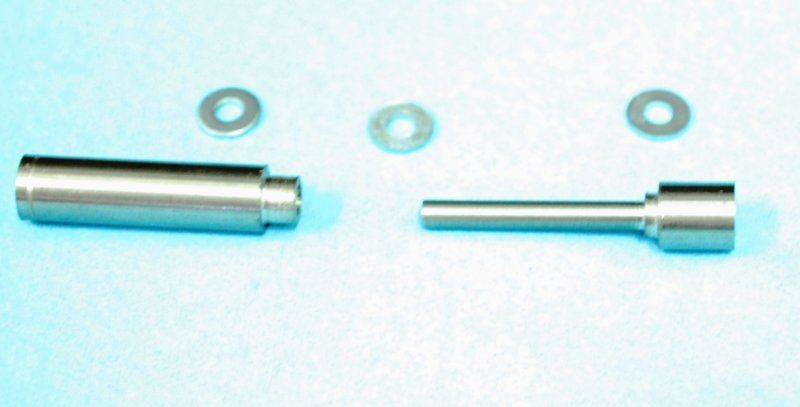
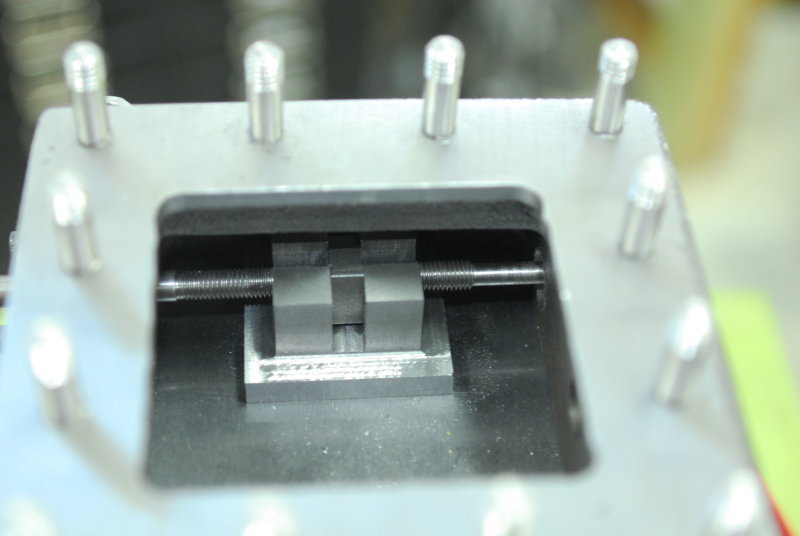
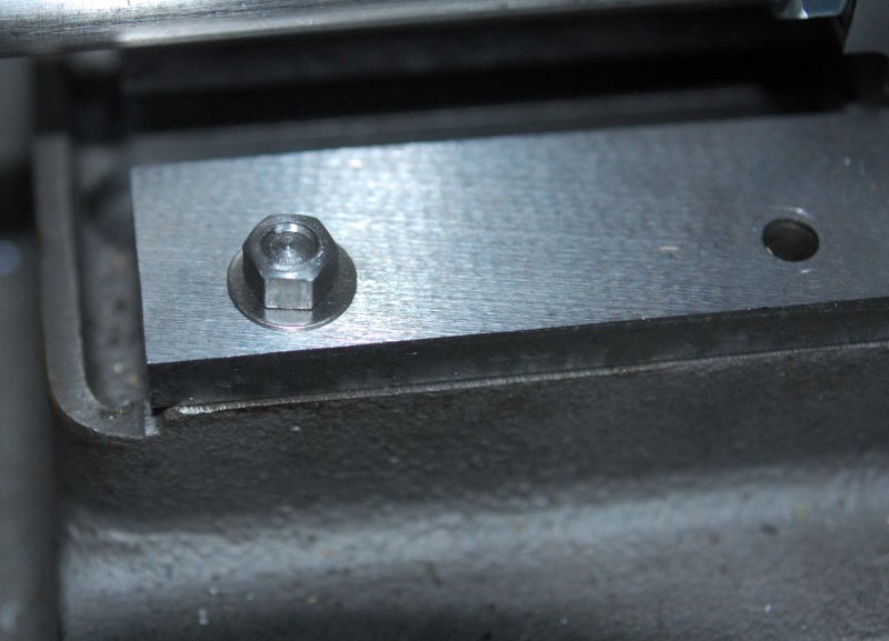
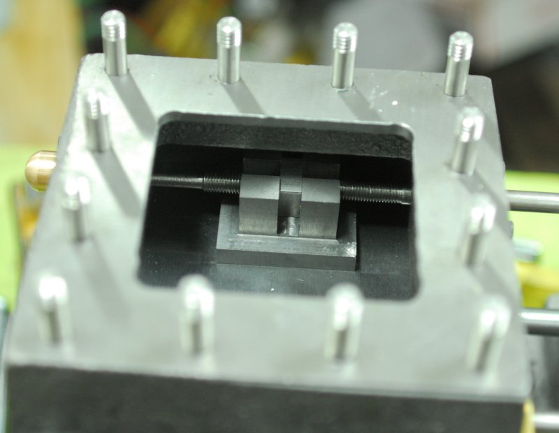
Today I received a box of steel flat washers so I could try on most for size. While the cover studs are no problem, I find that there is not enough space in the cylinder sides for a complete washer, and I will have to cut a flat side in them to fit. The studs for the steam chest to cylinder are about 1.5" long, and with all of them screwed into the cylinder I can't lower the chest cleanly onto them. Since I can attach the chest with screws, it seems to be a matter of a close fit in the holes drilled in the chest. I probably need to enlarge the clearance holes slightly.

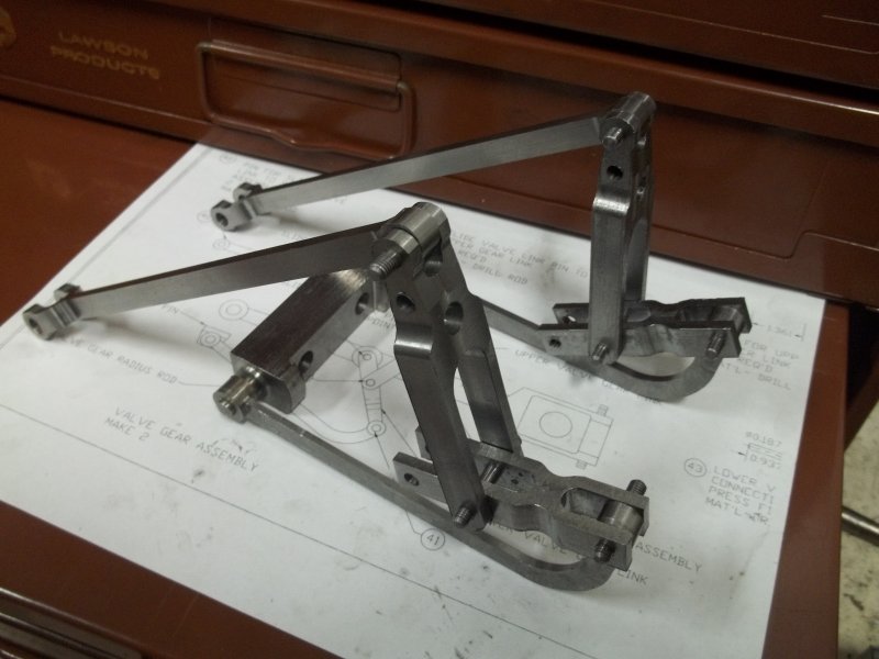
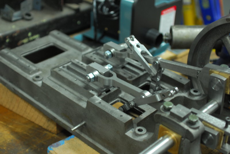
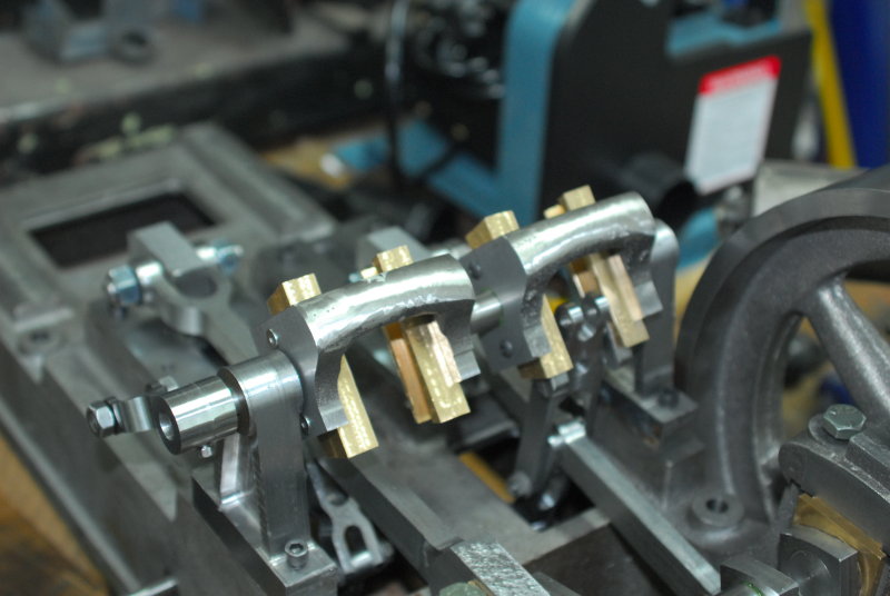
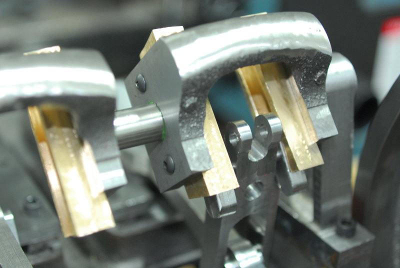
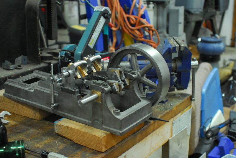
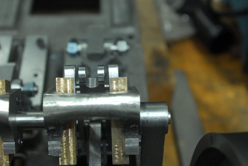
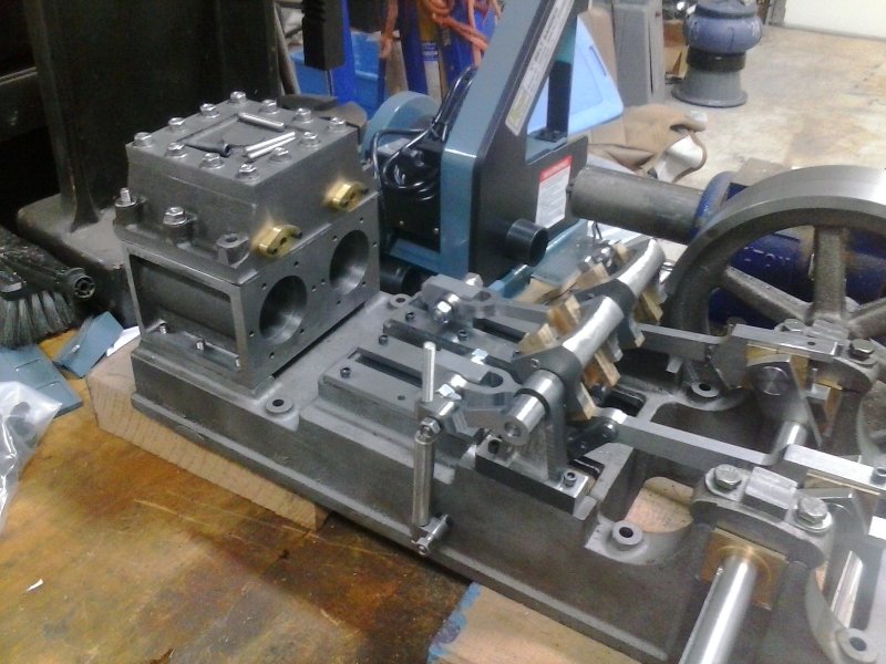
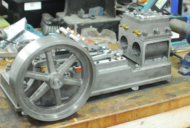
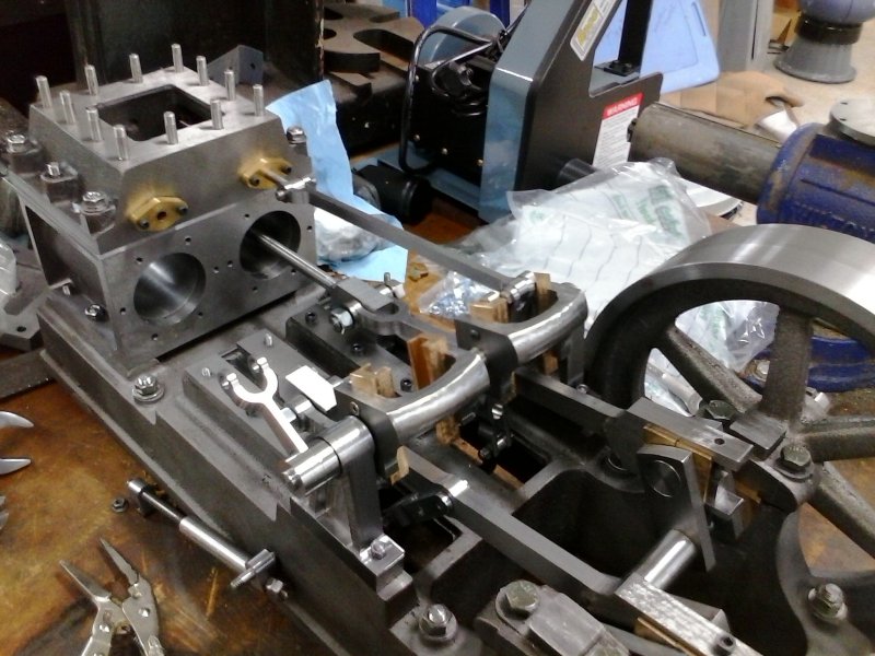
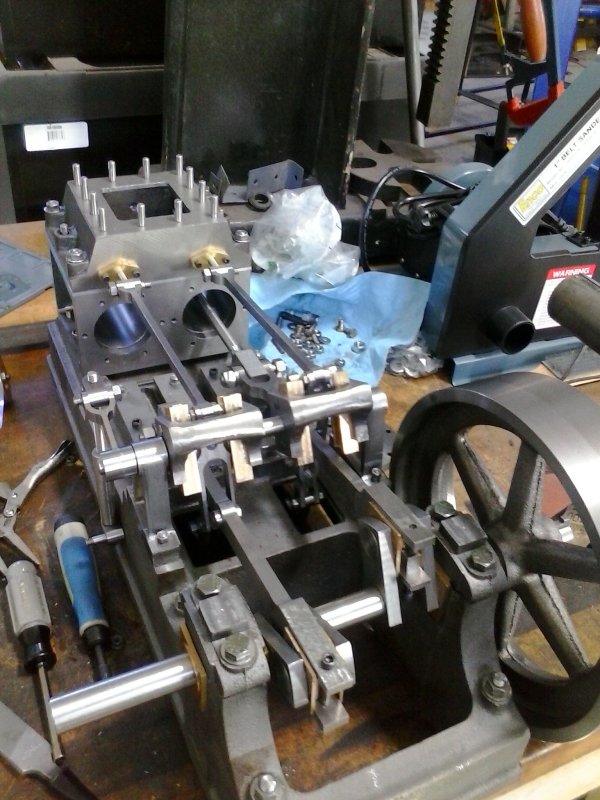
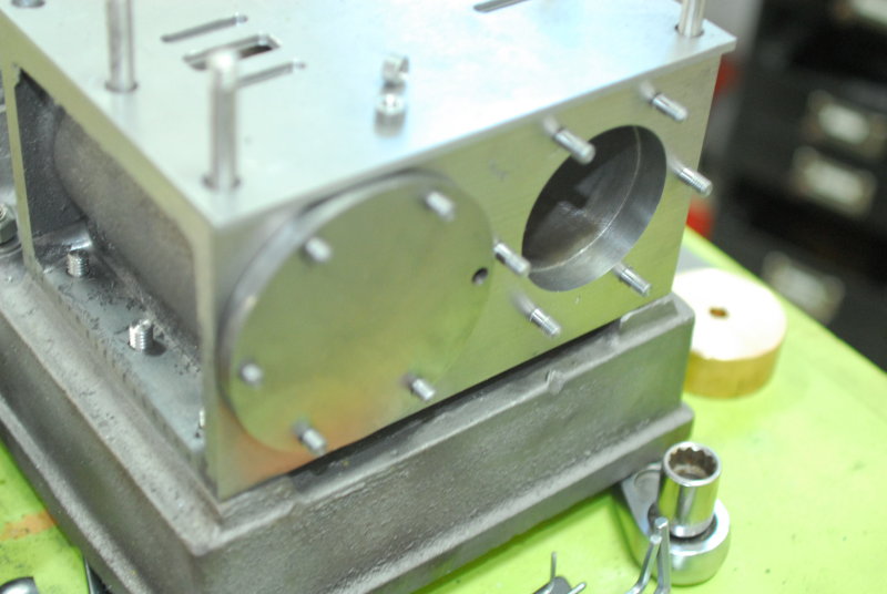
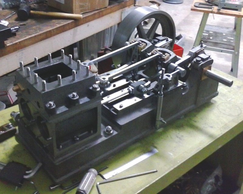
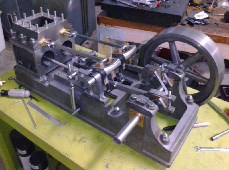
Here's a test assembly of where I've gotten to so far:

large.jpg


I need to make a goodly number of 10-32 studs for the cylinder covers, reversing stands, and crosshead guide plates, so I need to order more 3/16 drill rod for those.
 
Last few hours in the shop were spent making more studs: 10-32 for cylinder covers and crosshead guide bars until I ran out of stock, then 5/16-18 for the base.

I ordered some more drill rod from Enco, along with some 1/8" thick ground steel sheet for the valve plate. I had twice tried to grind the valve plate myself starting with 3/16 HRS. but each time the material warped. The smallest sheet that works is 5x24", so enough for 3 of these.

Should get delivery tomorrow afternoon.
 
The method I had tried to attach the end boss to the valve rods using loctite was not successful. I was able to pull it off the end of the rod with only moderate hand pressure. I was reluctant to use SS for fear of warping the thin rods, so came up with this idea:

large.jpg


The rod ends are threaded 1/4-28, while the boss is drilled and tapped the same. After applying high strength thread locker and curing overnight, I then secure the rod end in a 5C square collet block and mill the boss to width. Finally the boss is reamed. The cross pin helps secure the boss from turning since the end of rod has been reamed to the same radius. The photo shows my test piece secured in the end of the valve link.

So today I made two of the bosses:

large.jpg


And have them attached and curing to the rods awaiting finishing the next shop session.

large.jpg


Also made the studs for mounting to the sub-base, eventually. For now made some "feet" that raise the base above the bottom of the flywheel. These make moving the engine around the workbench easier.

large.jpg


large.jpg


Got the UPS delivery today with materials for finishing more studs, plus the valve plate.
 
Back in the shop aiming to finish the valve rods. I insert the rod into the 5C collet block and use a height gauge on the surface plate to align it. The over to the mill to bring the boss to the desired thickness (.370"). By taking small passes and turning the block over, the rod remains centered on the boss.

large.jpg


Fitted to the valve link rod:

large.jpg
 
Did a first test assembly of one half of the engine with all the moving parts other than the piston and valve in place. Turning the flywheel gives gives a quite smooth action throughout the full cycle, which is encouraging. As well, the tilt of the reversing mechanism doesn't move during the action even if it's not locked. Also a good sign:

large.jpg


I discovered some dimension errors in the drawings making the upper valve link too wide to pass between the bronze slide guides, so some trimming was necessary to give clearance. The same is true of the pin that connects the valve link rod to the upper link, since it too must clear the guides. I'm using two thin nuts on each end of the pin.
 
Last time in the shop I tweaked the valve plate into its final dimensions, so now it remains to mill the ports.

Then as a sideline I decided to try to make some model scale 10-32 washers starting with US standard size washers. I need to turn the stock washer diameter down from .5" to .375", and I'll need about 50 of these. So I came up with this, made from 1/2" rod:

large.jpg


The washers fit over the right hand piece, which is then inserted into the left to clamp the washers. Left hand piece is held in the lathe check with the right held in a live center.

Works sort of OK, but it's hard to get enough clamping pressure to allow a full depth cut. Worked best taking .02" per pass with a fast feed. Did about 10 washers at a time.

The 10-32 model scale nuts from American Model Engineering take a 9/32 wrench. This size wrench is not part of standard imperial wrench sets, so I found and ordered one on eBay.
 
Last edited:
Spent most of the day remaking one of the upper valve links. Quite a number of setups both CNC and manual:

large.jpg


The drawing for this part is missing some dimensions, among which is the position of the "shoulder". This needs to clear the sliders as can be seen here:

large.jpg


The prior piece would have interfered ( but that's not the reason for the redo; I drilled one of the cross holes out of parallel).
 
I assembled the remaining side of the valve system after a small amount of fettling in order to get free range of motion:

large.jpg


I discovered one potential dimension problem. While the valve rod is shown as being 5.665" long and mine are 5.75", the ends of the rods still come out of the guides but approximately 1/8". Since the steam chest wall is nominally .75" thick and only 1/2" of the guide is inside the wall, I think I'll just make the guides 1/4" longer.

The valve rods have a total travel of very close to 1" with the current inclination of the slides. Next task will be to install the valves themselves onto the rods.
 
Decided to install a valve on one side and see how the valve motion adjustment can work. It takes a bit of agility to drop the steam chest over the studs and land the valve "nut" into the slot on the valve. Once that was accomplished I adjusted the travel by turning the valve rod until I got a good approximation of balance travel between the two steam ports.

large.jpg


When I tried it with the other side the warp in the valve rod caused all sorts of problems, so I decided to remake it. While the plans call for 2.3" of 1/4-28 thread, that's more than is needed, since I made the valve differently. Sp after measuring where the nut was on the good rod:

large.jpg


I decided to make the new one with 1.5" of thread, but even this amount has a great deal of leeway.

large.jpg


The new one is straight, so avoids many problems that were caused by the warped one.
 
Installed the conrod bearing "keepers". These are small wedges that are tightened by a 10-32 screw that passes through them vertically. Stock screws didn't have enough thread length, so I used some 10-32 threaded rod from Enco. Plans call for a 3-degree (actually .05" taper per inch) but apparently I tapered the edge of the bearing 5 degrees, so made the wedge to match. Photo appears that I mounted it sideways.

large.jpg


When finished there will be a steel block on the end of the conrods held by tension of the threaded rod by nuts on each end to tighten the end. Not standard practice by any means.

Also finished the studs for the rear cylinder covers. 7 studs in one session is all I have patience for.

large.jpg
 
I found some SS 10-32 washers at Ace hardware that will work as well or better than the ones I bashed out earlier. And they are .02" thick, about half that of the others.

large.jpg


Then today I finally got a complete assembly with all moving parts save the pistons and one flywheel:

large.jpg


large.jpg


large.jpg


With the valve in place I did a dry run of timing the engine. First set the reversing mechanism so that the slides are vertical. Then position the valves, by turning the valve rods, so that neither steam port is exposed when the flywheel is turned. The valves still move. Then I gradually turn the reversing shaft to tilt the slides so that the top moves towards the cylinder. After a few degrees I turn the flywheel to see if either steam port is exposed. Then I adjust the valve via its rods until both steam ports are opened the same amount by one turn of the flywheel.

It doesn't take much inclination of the slides to have both ports open fully, and further inclination increases the valve travel further. I probably need stops of some sort on the threaded shaft to prevent too much travel else the valve rod will hit the guide. With this inclination the flywheels will turn clockwise when views from the side of the reversing gear.

I made an error in the positioning of the reversing lever, making it perpendicular to the slides rather than at a lower angle. As it sits now I don't have enough thread on the reversing shaft to incline the slide backwards to get reverse. Since the reversing shaft isn't fixed, I can just replace the threaded rod portion with a longer piece for now.
 
Back
Top