Joy's Valve Gear Horizontal Engine

Home Model Engine Machinist Forum

Help Support Home Model Engine Machinist Forum:

This site may earn a commission from merchant affiliate links, including eBay, Amazon, and others.
Reverse machined and freed from matrix. Shown with the casting version on the left:

large.jpg


The heights were slightly off, so used the setup on the BP to level:

large.jpg


Tested alignment on the engine base to find one of the mounting holes in the journal is slightly off center. I will need to enlarge it later. Still with three of the mounting screws tightened down a length of drill rod does turn.

large.jpg
 
Made a start on the valve linkages. Start with a 10" piece of .875" diameter 1144 stress-proof steel, and then turn a 1/2" diameter x 1/2" long boss in one end. Make two of these.

large.jpg


Then make a square block of aluminum 1" thick and 1.725" on each side, with a 1/2" through hole in the center. With 12" jaws mounted on the CNC milling vise, clamp the assembly together using a square collet block on one end.

large.jpg


Mill the top profile, then rotate the block/bar/square 90 degrees in the vise to mill the side profile. The face of the collet block is used to repeat the x0.0 value each time the assembly is turned. Y0 is the centerline.

large.jpg


All for today:

large.jpg


Next session need to use the same assembly to drill the holes for the pins and machine the bosses, before cutting the rod free. Hopefully can use the same technique on the conrods, although they are quite a bit larger.
 
More ops on the valve links:

- Cut off the ends, then drilled and reamed the holes:

large.jpg


- With the 6" jaws back in the vise, the 3/8" rod can be used to find the hole's center in X

large.jpg


- machine the opening in the big end.

large.jpg


- Turn 90 degrees to round the ends

large.jpg


- Completed!

large.jpg


Same techniques with larger stock for the conrods. Will be a tight fit even with the 12" vise jaws.
 
Spent a few hours making the valve link pivot. Started with a 2.75" length of 1.25" diameter steel rod that I faced on the lathe and drilled 1/4" holes 1" deep in each end. Then clamped in the Bridgeport milling vise.

large.jpg


Then lots of cranking the dials milling most of it away in order to end up with this:

large.jpg


The drawings show a more complex shape, but since this part is screwed to the underside of the base casting where it cannot be seen, I used the Kiss principle. The only necessity is that the radius rods pivot on the 1/4" rods attached to the sides with loctite. The drawings also show a 1/16" hole drilled through the rods at their ends; I presumed this is for a cotter pin to retain the radius rods, so I decided to turn grooves and use e-clips for this purpose.
 
Started the radius rods by cutting the profiles through a piece of CRS after drilling and reaming the end holes .188.

large.jpg


The CAM program left three "tabs" on each rod to keep the parts from falling through. The tabs were located on parts of the rods that won't be visible in operation. Used the vertical bandsaw to extract the parts from the stock. The pic shows the cut off tabs. I would have been wiser to machine the sides and boss before the profile, as it appears there was some vibration affecting the cut quality.

large.jpg


After milling off the tabs on the Bridgeport, I turned the rods over to clean the scale off the back side in order to measure the thickness left.

large.jpg


I'll need a simple fixture next time out to finish.

large.jpg
 
A bit more progress over the last week:

Radius rods show on the pivot plus the first ops on the upper and lower links -

large.jpg


First op on the reversing lever -

large.jpg


Next ops on the reversing lever -

large.jpg


Now to machine the other side of the reversing lever a soft jaw pocket to hold it -

large.jpg


Securely clamped -

large.jpg


And third ops to finish -

large.jpg


Finished reversing lever and upper valve links -

large.jpg


I've decided it's time to start on the conrods, the longest pieces on the engine. Stock is 1.75" diameter stress-proof steel and I need 11" exposed to the endmill to use the same type setus as for the slide valve links. That means only 1/2" left to clamp on each end of the 12" vise jaws. Next time out I'll do a setup and see how secure it seems.
 
After preparing the stock for the conrods, I confirmed my suspicion that even the 12" vise jaws are too short to hold it the same was as for the valve link arms. I need to buy some steel for a fixture, so in the meantime I started on the main bearings this afternoon.

Since 660 bearing bronze seems to be available only as round rods, I bought a foot of 1.5" diameter rod in order to be able to mill the .75x1.25" cross section. Only in hindsight did I realize that each half of a split bearing is .75x.675, so a smaller rod would have worked. Duh. Anyway, cut of 3" of the stock and faced each end on the lathe.

large.jpg


Then rough squared it using y-axis of the mill; with soft metal this is the fastest as I can cut each side in one pass.

large.jpg


Scribed to saw in 4 pieces:

large.jpg


This is a technique I came up with to cut small pieces on the vertical bandsaw:

large.jpg


Further milling yielded these 4 pieces:

large.jpg


Then glued together using 3M high-strength adhesive.

large.jpg


I know it's common to soft solder bearing halves for boring the center hole, esp. using a 4-jaw lathe chuck, but I will drill and ream the .75" center hole on the mill. With the halves clamped in the vise, the glue is mainly a means of keeping each set separate. After the holes are done, I'll wait for the conrods to fit the bearings.
 
Quick bit of CNC milling today. Used some of the 1.5" bronze rod for the first ops on the valve packing glands, as shown here:

large.jpg


Then chucked in the lathe by the round 1/2" boss and turned to final thickness. Results shown with the split bushings; here I interpolated the holes on the CNC mill and reamed .75".

large.jpg


I was planning to drill the holes for the valve rods in situ after attaching to the steam chest, but that's probably overkill.
 
Instead of actually cutting metal, the past two days have been spent in learning basic Solidworks, since I was able to get a free student edition version as a US veteran.

Here's my first cut at modeling parts and an assembly of the conrod, bearing, and the two valve links:

conrod.jpg
 
Finally got to cutting metal on the first conrod, using the same method for holding the round stock as for the valve link rods. "Fixture" starts as a length of 1/4" HRS to which I bolted a pair of parallels to one edge. The collet block and its partner are held against the parallels with "Mighty-Bite" clamps, and both ends then clamped vertically. Here's the workpiece on the fixture after the first ops:

large.jpg


Rotate the setup 90 degrees and reclamp, then further ops:

large.jpg


Finally flip 180 to do the details on the inverse side.

large.jpg


The surface finish isn't as nice as I'd hoped coming off the mill, so some hand work will be needed after the rest of the milling.
 
The conrods have been a "struggle" given the size of the parts, their odd size, and the number of ops needed. Here's a week's worth of effort.

After machine the four profiles, I machines some soft jaws to hold the shaft:

large.jpg


Then I could do the machining ops on each end.

large.jpg


large.jpg


Only a few ops to go:

large.jpg


On the first one I made a mistake, programming the bottom profile as a .375 endmill but using a .5" endmill. The result is still functional but is not symmetric. Given the amount of work to get this far I'm going to finish it, reserving the option to remake in the future. I've learned enough making these two that the third would take considerably less time, though still not trivial.
 
Some slow progress the past two days: yesterday finished the machining ops on both conrods, and today fitted one of the split bearings to its rod.

large.jpg


The bearing machining was manual and was lots of "whittling" away at the bronze until it fit. I measured the thickness of the big end and calculated the offsets from center to cut the top and bottom slots. Using a 3/8" endmill with an estimate of +/- .110", I found that I got a nice sliding fit at +/- .114", so all the rest of the slots were cut at that width. First task was to cut the top and bottom slots to depth equally so that the bearing could enter the conrod opening. Then I split the bearing halves and did the front and back slots individually. The far end slot is cut at a 5-degree angle from vertical to allow the tapered keeper to widge the bearing against the crank.

As assembled initially, it's very stiff to turn. I need to relieve the main bearing. It appears that the conrod is slightly off from being straight front to back, as the big end is off center in the crank opening. This could either be warpage in machining, or else having the holes for the crosshead pin being slightly off from perpendicular. However, there's enough flex in the rod to allow it to be assembled to the bearing and crank as shown in the picture.

I still need to drill 1/16" holes for oiling.
 
Got back to the engine a bit this afternoon by machining the end journals of the crankshaft (slots for the gib keys) and then loctiting them to the rest of the crank. I also turned the conrod upside down, which made it line up much better. Using the flywheels to turn the crank, the entire drive of crankshaft, conrod, crosshead, and piston operate quite smoothly for a first cut without lubrication.
 
Some minor testing today. I drilled and tapped (1/4 NPT) air supply hole in the center of the rear face of the steam chest and did the same to the bottom of the exhaust hole in the cylinder block. I then bolted up the steam chest, its cover, and the cylinder block and applied air pressure. If all the ground surfaces were perfect then there should have been no leaks. But the interface between the cylinder and steam chest was by no means air tight. Therefore it appears gasketing will be needed.

Eventually the valve plate (ground on both sides) will be situated between the chest and cylinder. The fastening of the plate, as it currently sits, is just 3 through holes on each side. The drawing of the valve plate shows 4 additional through holes, two each along the front and back edges. However there are no matching holes shown on the drawings for either the chest or cylinder. Muncaster shows the 4 extra holes tapped into the cylinder. Simon extended 4 of the cover bolts for this purpose, but I think I'll plan to to just mill counterbores into the bottom surface of the chest to clear the screw heads.

It is more important that there be no leaks anywhere between the valve plate and the cylinder. I'll probably need to use a silicone gasket of some sort. The plate and steam chest interface is easier to seal and a paper gasket should work. I'll need to remake the valve plate as I messed up the first try.
 
Couple of little parts squeezed into some shop time. These are the "keepers" that wedge the split bearings together in the conrods. One side is angled 5 degrees to match the rear face of the bearing. The 10-32 screw causes it to rise until it presses the bearing.

large.jpg
 
Machined the second split bearing to fit the second conrod and assembled both rods between the crossheads and crankshaft. Turns by hand fairly easily and should wear in with use. I'll relieve the main bearings a bit when next disassembled.

large.jpg
 
Lots of little steps over a couple of afternoons to show, making the valve guides and valve packing glands. First, slice off about 4" from a 1.5" hex brass bar.

large.jpg


Skim just enough to make it 1.5" round bar:

large.jpg


Turn a 1/2" diameter spigot, then drill and ream 3/8" diameter .75" deep. Then repeat on the other end of the bar:

large.jpg


Then part off:

large.jpg


Turn some bearing bronze to 3/8" diameter and loctite into the spigots:

large.jpg


Next drill and ream a 1/2" hole in the round bar:

large.jpg


Now turn some bearing bronze to 1/2" diameter and drill/ream a 3/16" hole 1" deep, then part off and make one more:

large.jpg


Round the closed end of the bronze pieces using a corner rounding bit as a form tool. The bit has a flat that allows the boring bar holder to assure that the cutting edges are horizontal.

large.jpg


Face and part two discs from the 2" bar and loctite the bronze piece onto the disks. Let cure overnight.

large.jpg


Drill and ream the bronze inserts in the packing glands to 3/16 and face the gland disks (not shown). Then for each of the 4 pieces use the square collet block to drill clearance holes for 6-32 mounting screws:

large.jpg


Then move the collet block to the CNC mill to form the lozenge shape:

large.jpg


Finished parts:

large.jpg
 
Today I started drilling the holes on the front and back of the steam chest. Using the DRO on the "back" side, I located, drilled, and reamed 3/8" holes. These will eventually be enlarged to 1/2"+ for the valve guides, but I wanted to see how far off I might be in locating the rod side. On the rod side I drilled and reamed 1/4" holes.

large.jpg


When I fit the valve rods through the front it appeared that the rear holes were "off" by an eyeball measurement of .05" or so. Whether this was because the holes were off or the rods aren't straight was hard to tell. Nevertheless, I figured to correct any misalignment via the rear, so I proceeded to counterbore the front using a .5" endmill followed by a .501" reamer.

large.jpg


Now, because there is less material around the .25" hole, it's possible to align the rods using the wiggle room provide. But when I then try to install the valve glands everything gets tight again. Clearly all three bores are not aligned to tenths.

So here's where it sits as of today:

large.jpg


My thoughts now is to widen both front and back bores to .551" via a 14mm reamer, giving room to adjust both the guides and glands into line. But if anyone has a better idea between now and Monday please let me have your thoughts.
 
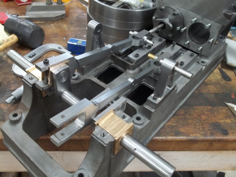
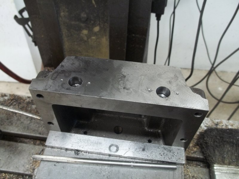
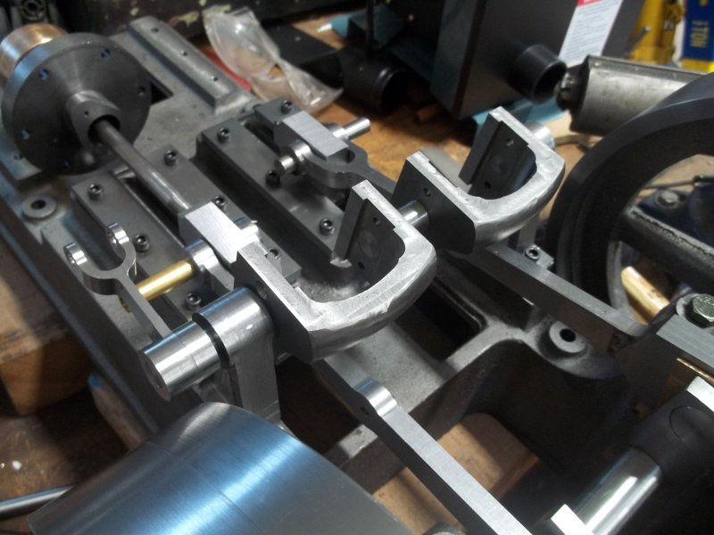
After boring and reaming the holes for the valve guides in the steam chest, I am able to have the valve rods go from the packing gland to the guides. However, they only slide easiy when rotated to a favored position. Evidently the rods are not perfectly straight, which is not that surprising for 1/4" bar that's 4" long. I still need to fabricate and attach the rod ends, and will attempt to position them in the favored orientation, but otherwise I'll consider opening up the valve guide diameter and/or reducing the diameter of the end of the rod that slides in the guides.

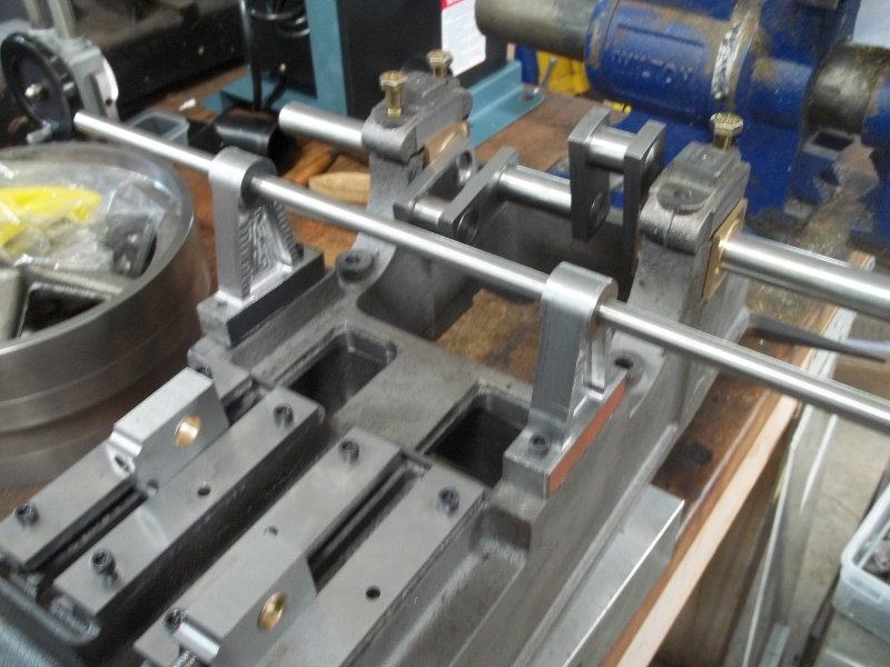
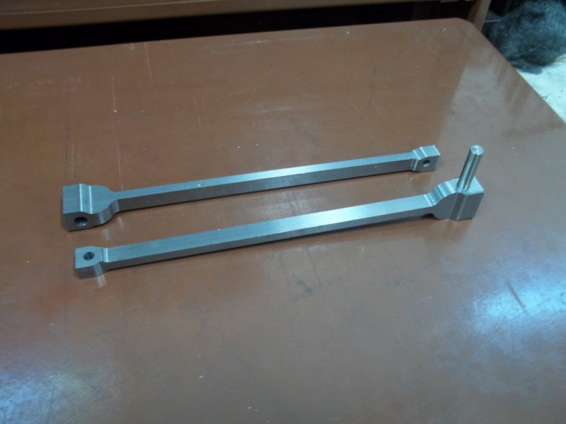
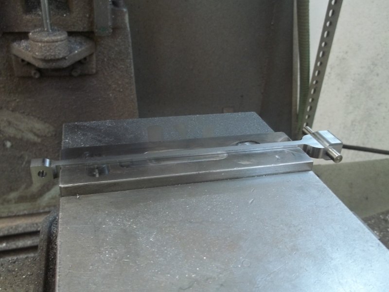
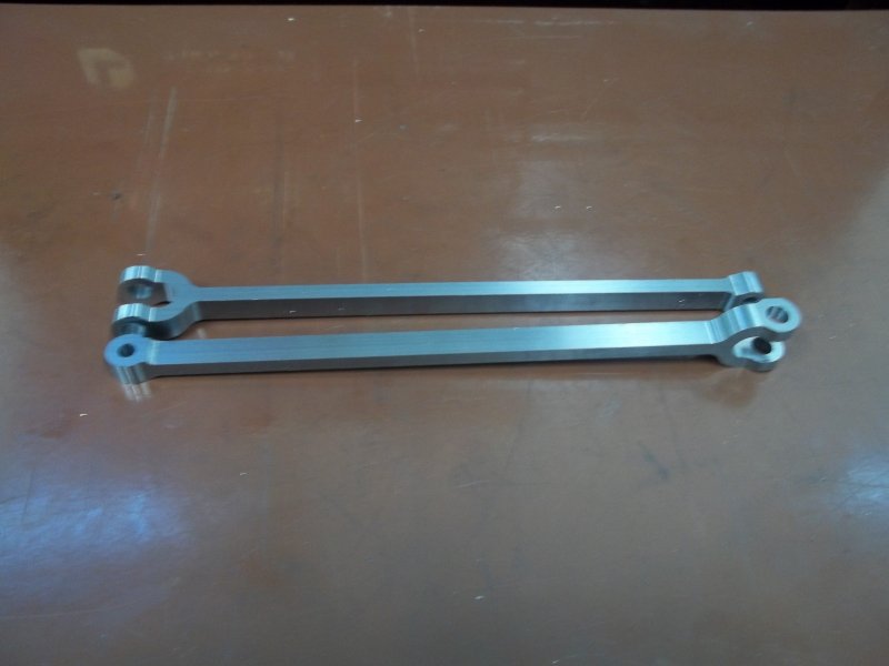
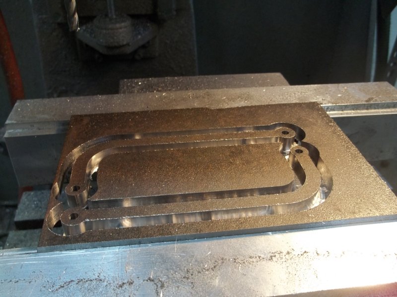
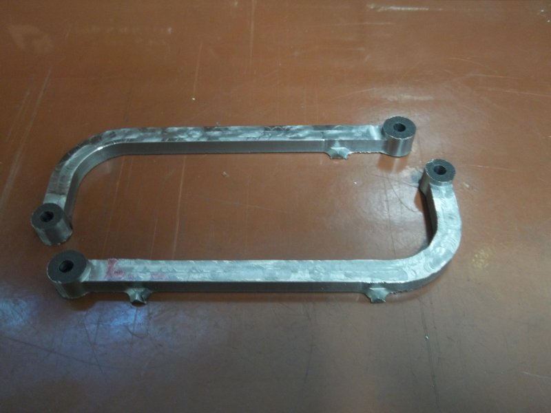
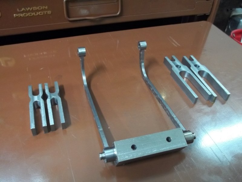
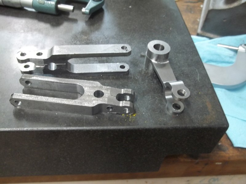
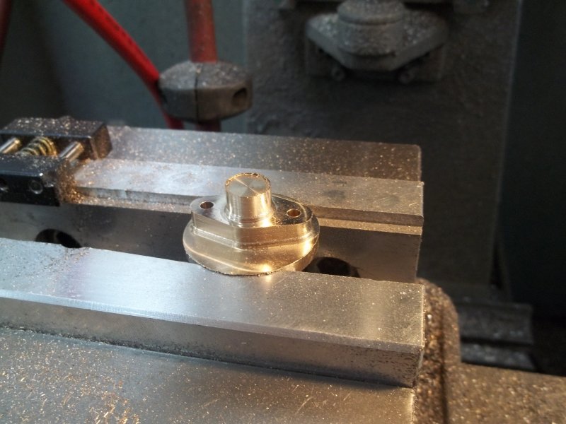
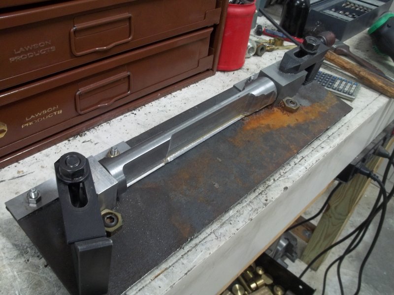
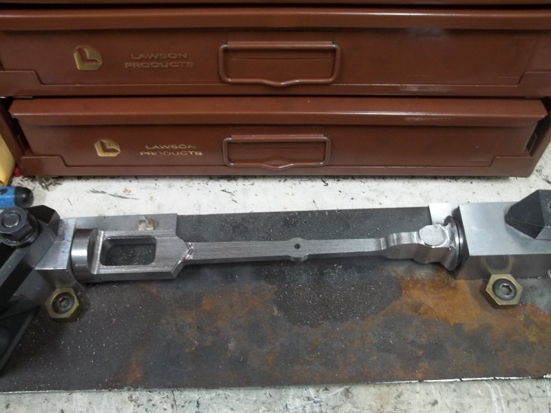
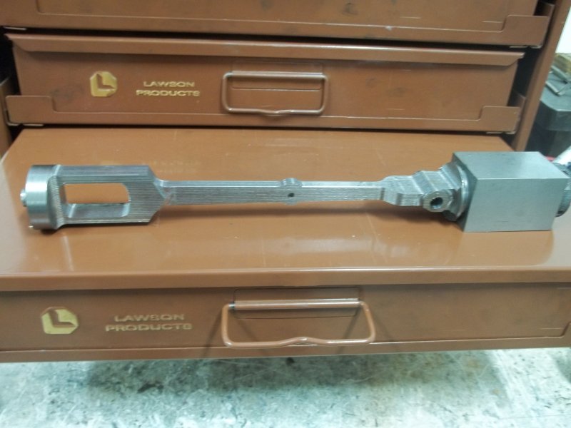
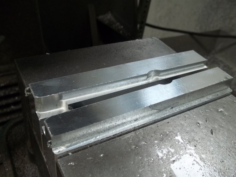
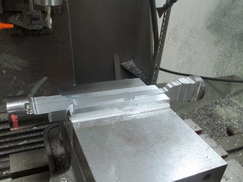
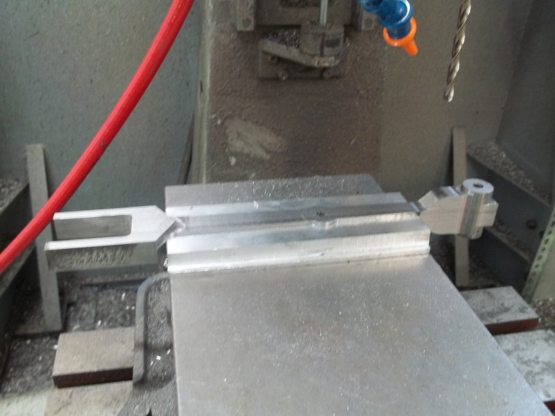
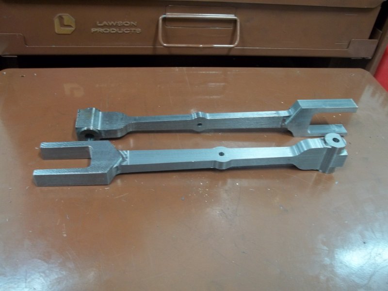
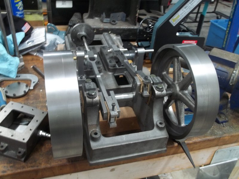
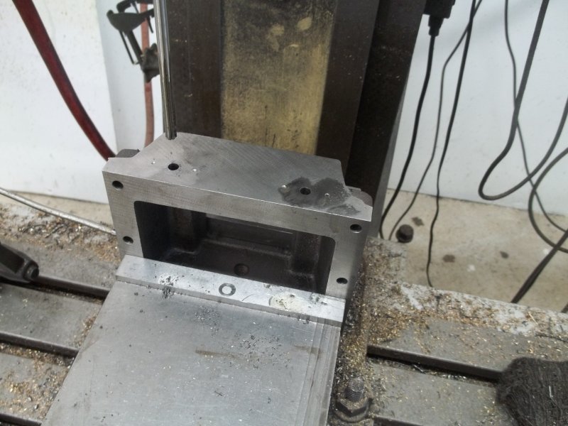
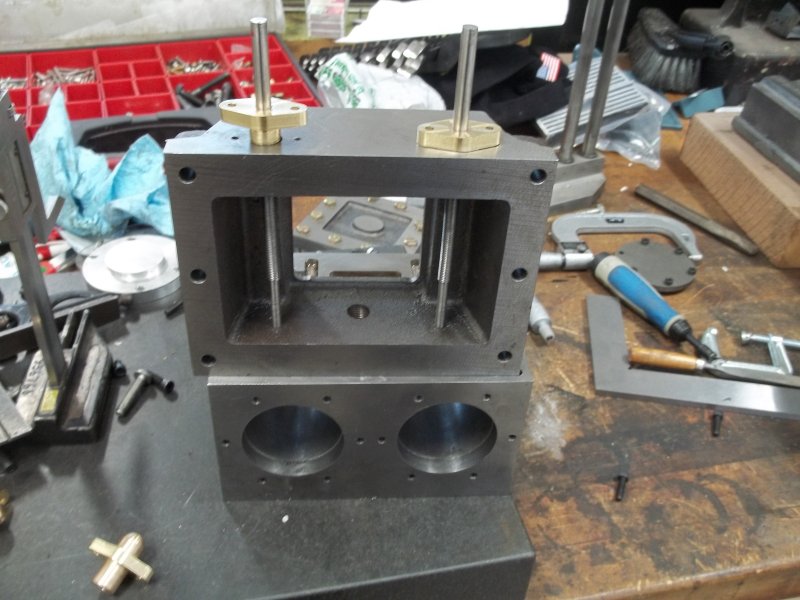
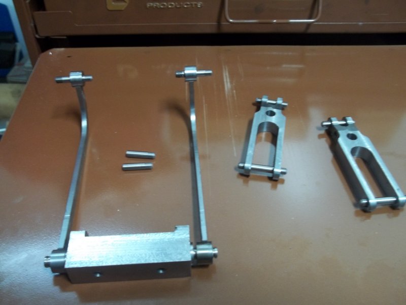
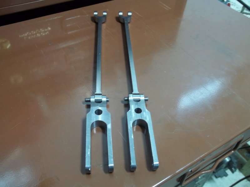
Another task I undertook was finally attaching the two rocker slide frames with sections of drill rod, loctited (620) into place. The rod that holds the reversing lever has a flat milled in the bottom to accommodate a 5-40 set screw. Here's the test assembly:

large.jpg


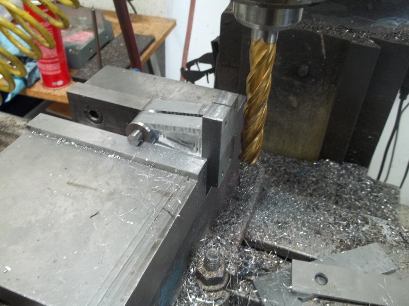
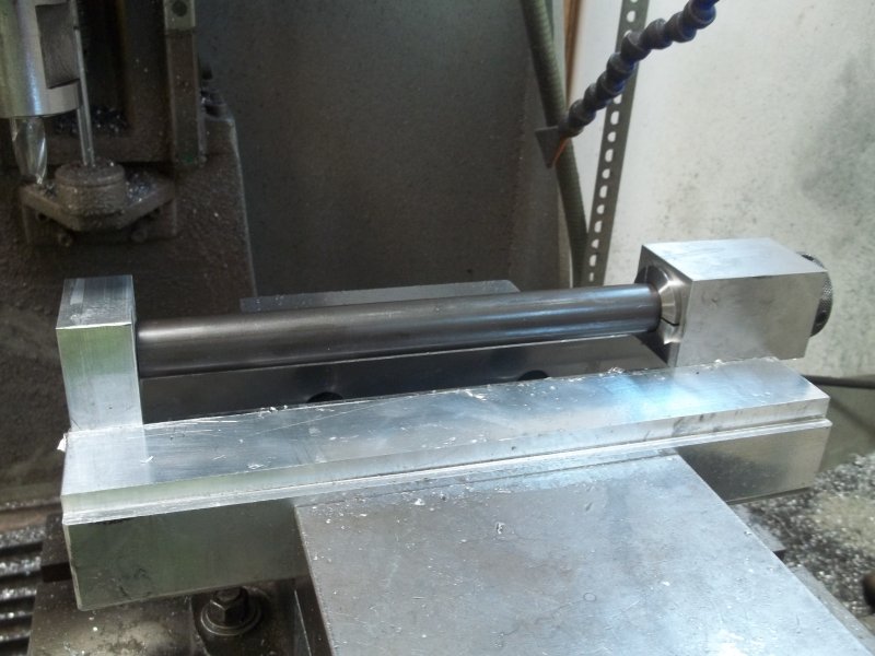
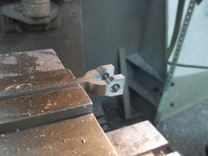
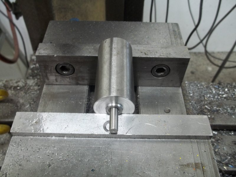
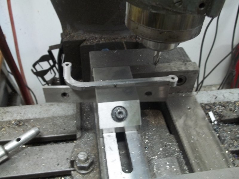
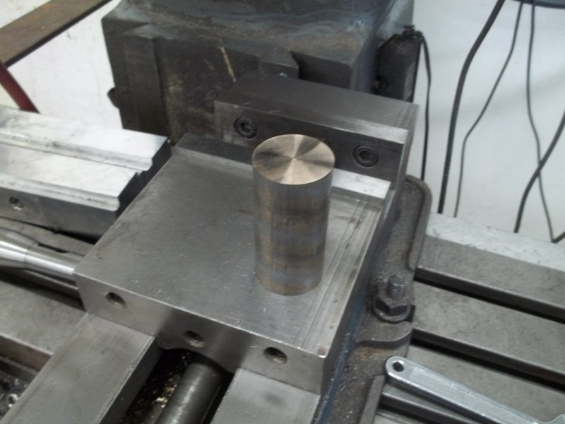
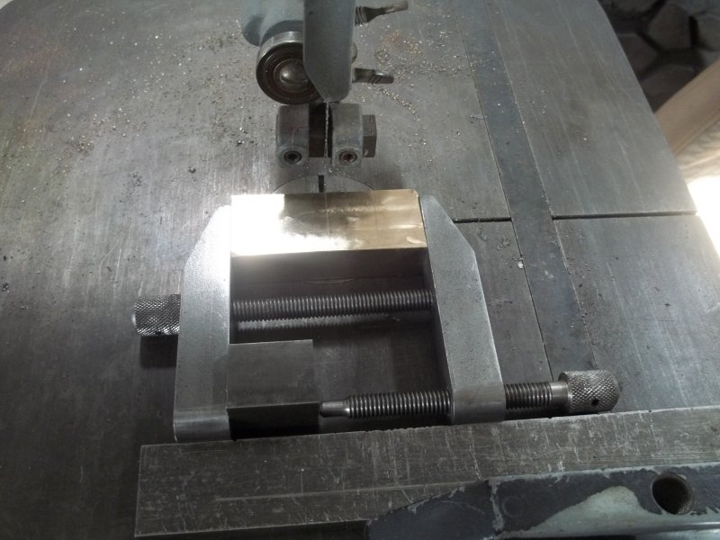
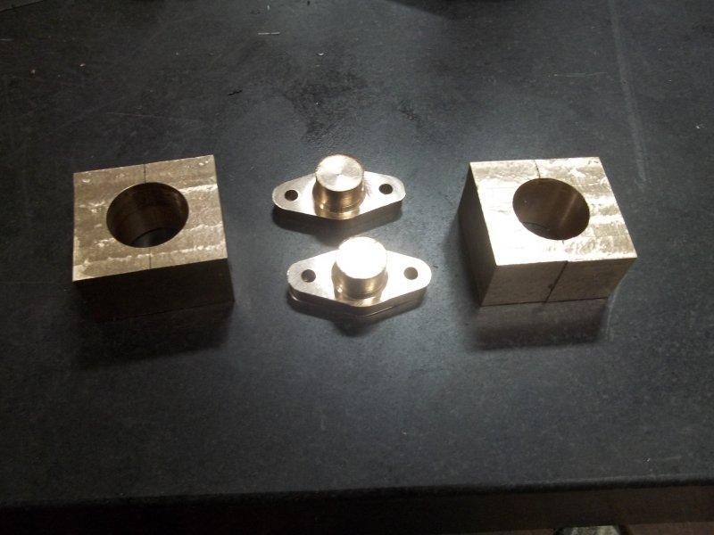
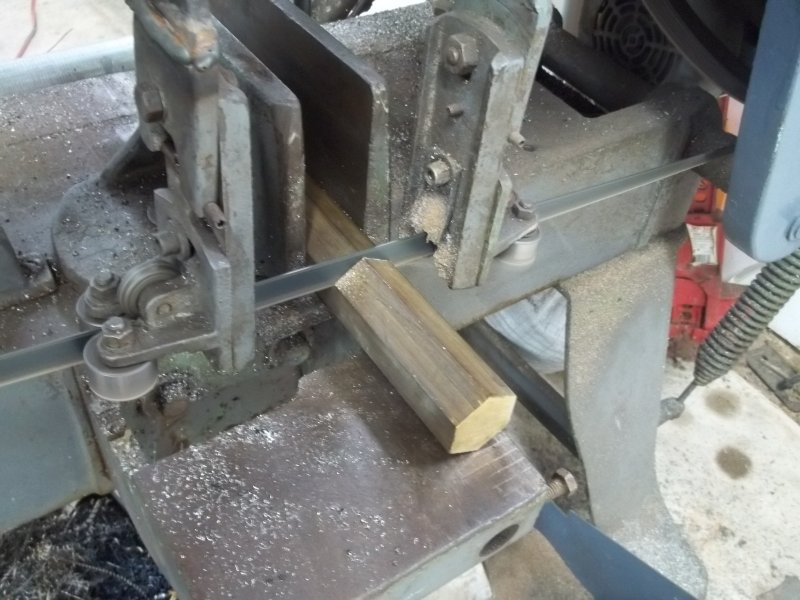
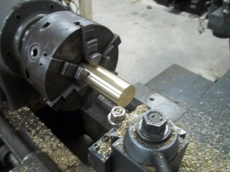
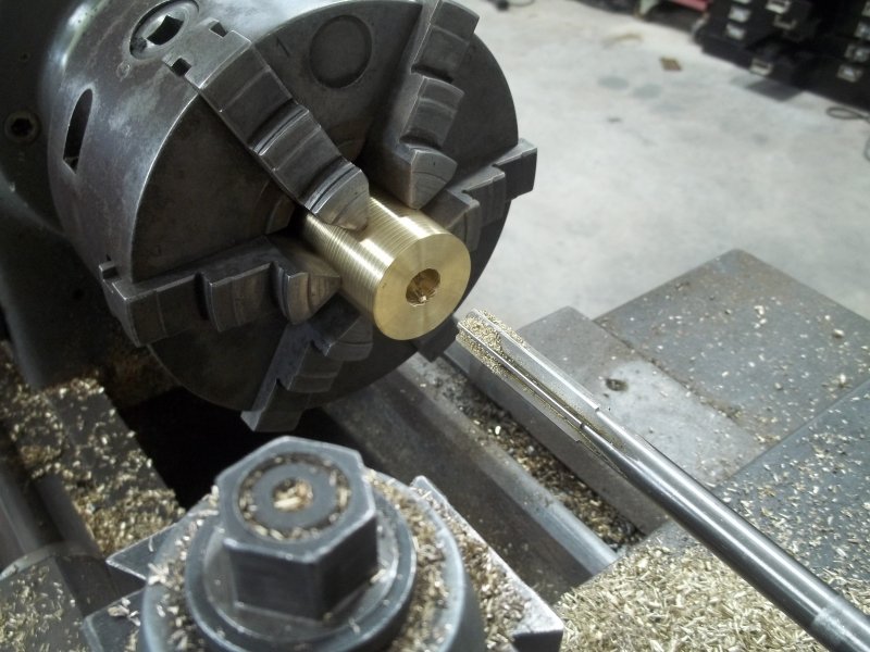
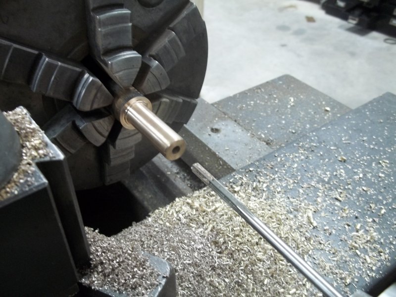
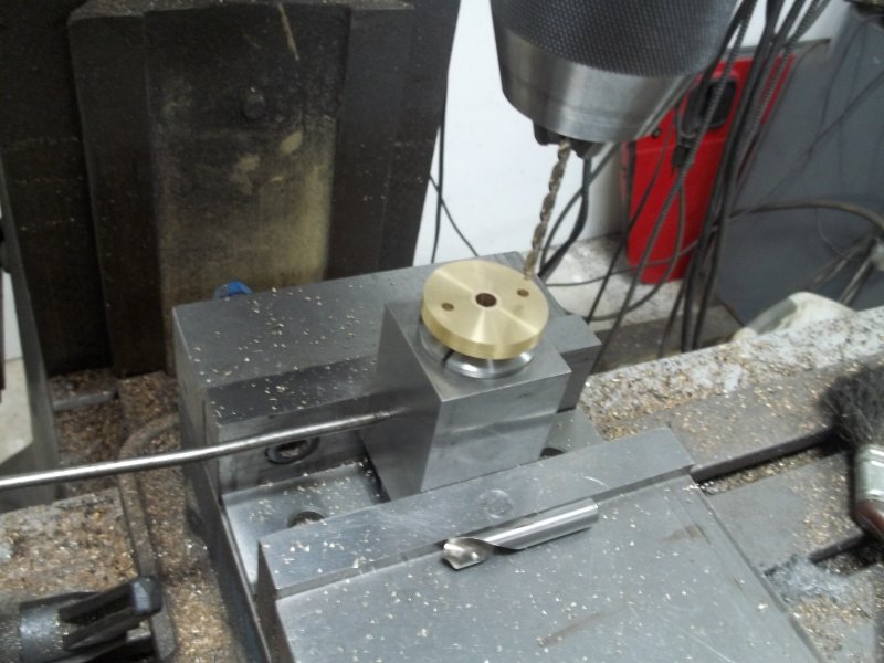
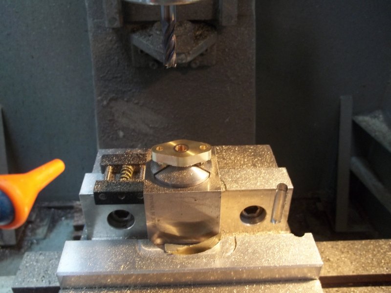
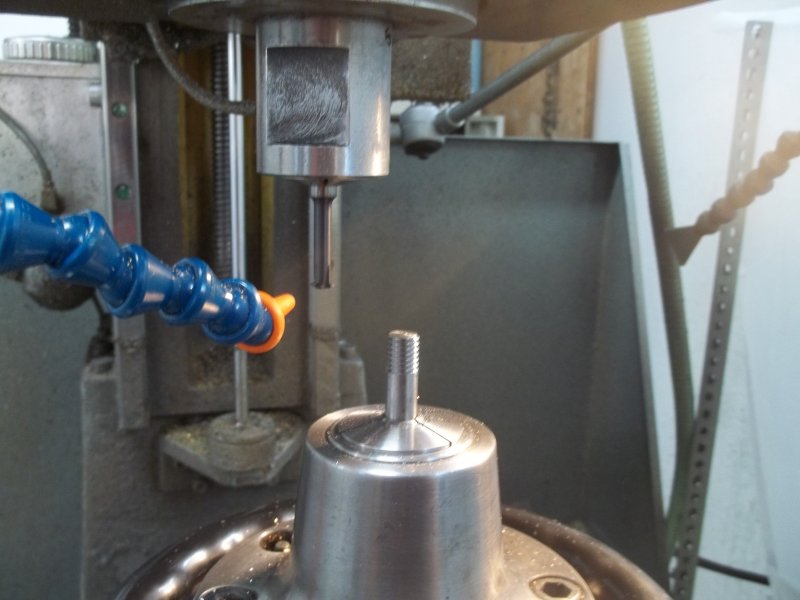
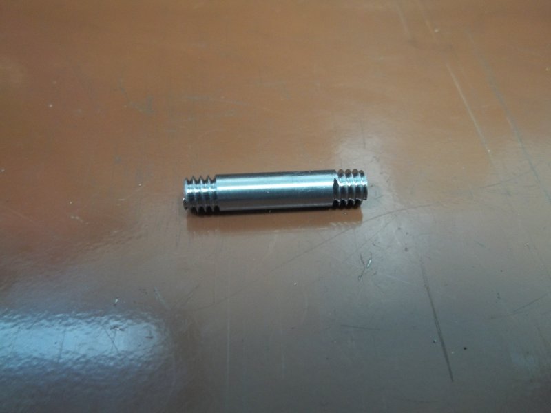
The engine has a number of pins, threaded on each end similar to studs, for assembling various components. I decided to tackle the two that connect the conrods to the crossheads, using thread milling. Since I'll do all the studs in the same general way, this was a test. The pieces in question are 3/8" drill rod threaded 16 TPI. Some years ago I bought the spindle nose from a Monarch 10EE (same as my lathe) that was being parted out. The spindle is a D1-3 and was mounted on a round piece of ground steel. So I can mount my Sjogren 5C collet check, and clamp the entire assembly in the CNC mill vise. After centering, I can thread mill any size rod for which I have a 5C collet and which is up to about 8" long. For "production" use, the workpiece can be positioned quickly: with the threadmill at X0Y0Z0, raise the rod in the collet to touch the bottom of the tool, then tighten the check and press the start button.

large.jpg


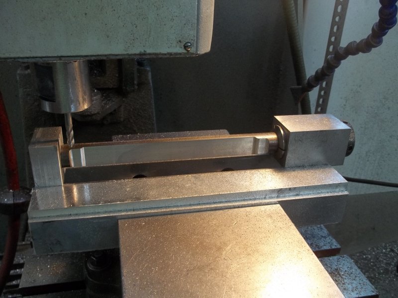
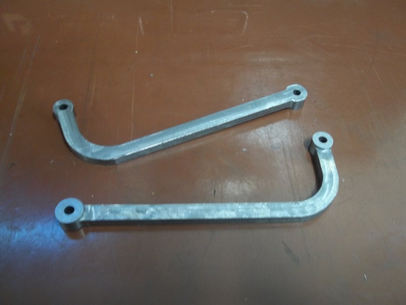
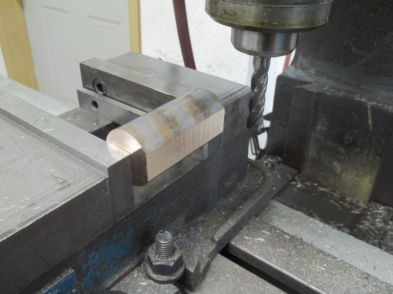
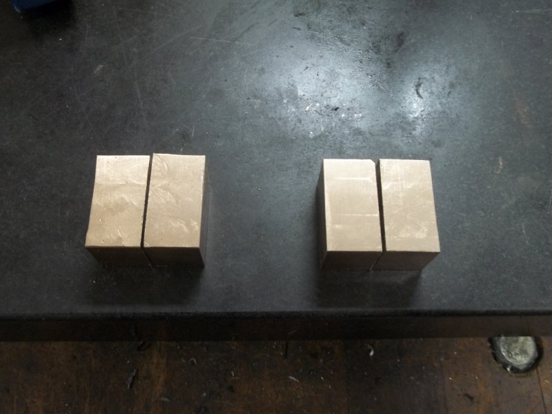
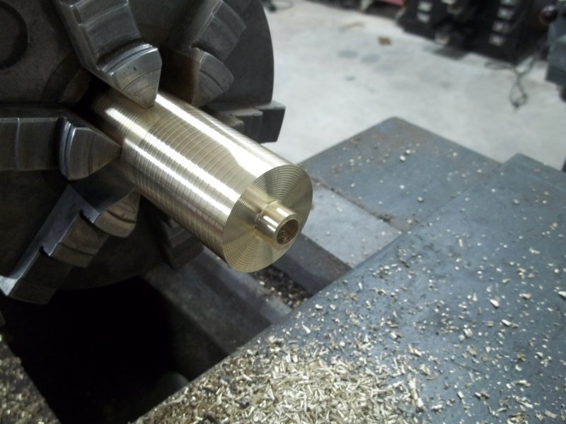
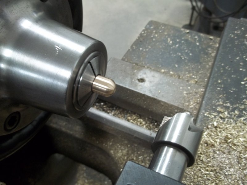
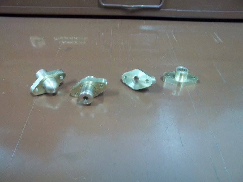
And proof that it works:

large.jpg


It takes a few tried in the CAM program to get the minor diameter of the thread and the diameter of the threadmill matched up to allow a nut to screw on, but once set the CNC programs can be reused many times over. I'm doing 3 passes for the 3/8" drill rod and 2 passes for 1/4", followed by a spring pass at final depth. The spring pass does seem to be a necessity.

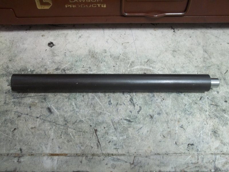
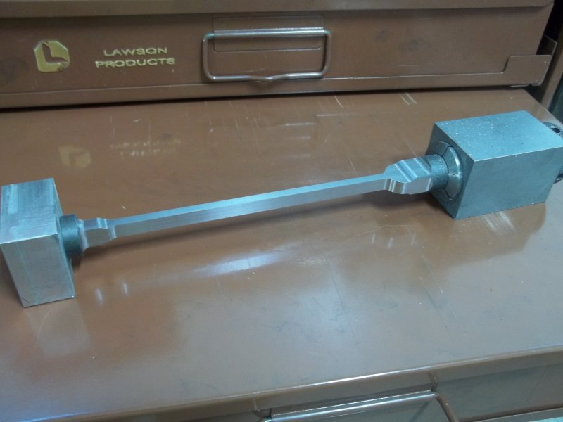
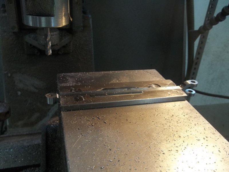
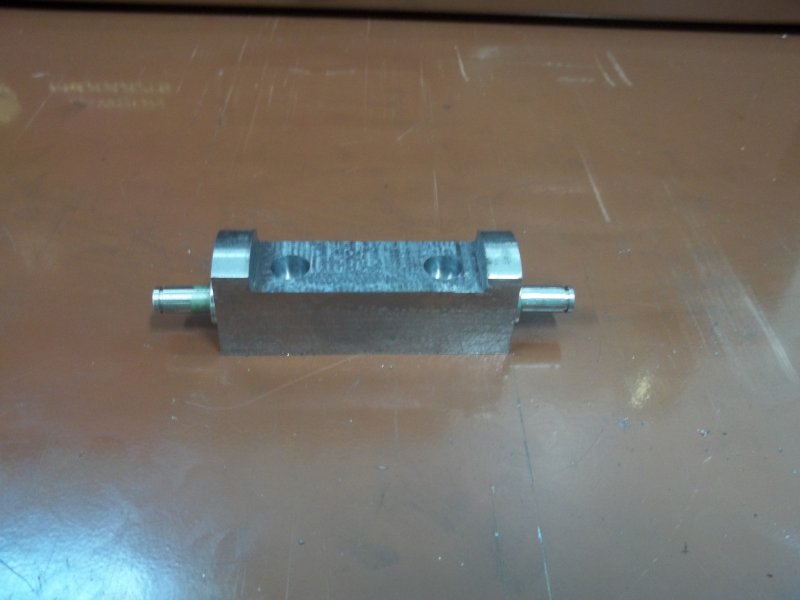
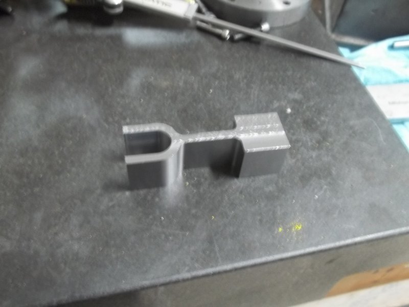
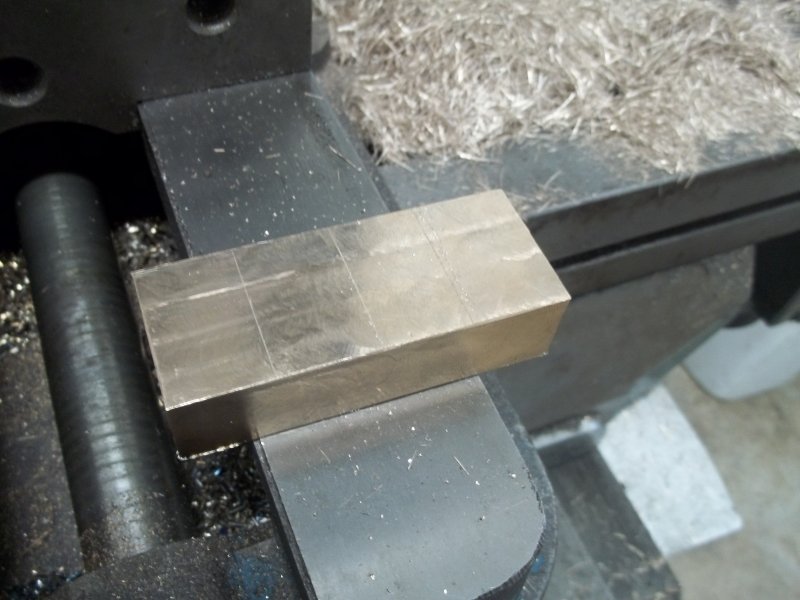
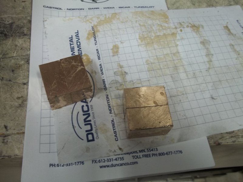
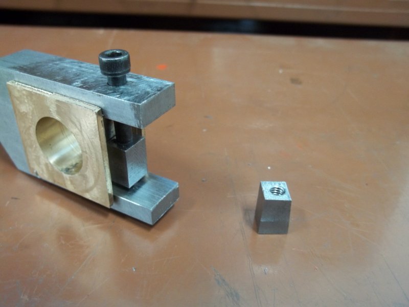
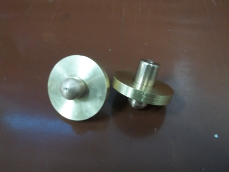
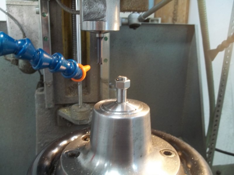
After making the two 3/8" pins, I did the programming and test for 1/4", since I'll need a good number of studs of this size. Here's my little sample:

large.jpg


One advantage of threading this way is that there's no burr at the end of the thread.
 
More thread milling today, this time 10-32 threads on 3/16 drill rod. The plans call for 8-32, but I can see no reason for the smaller threads since these are the pins for connecting all the valve linkages. Once the programming is done then the threading is a no-brainer. The thread mill is a tiny little thing. Here are the pins showing where they go:

large.jpg


The pin connecting the lower valve link and the conrods is specified as a press fit, since both ends need to clear the upper valve link. I think this will make disassembling difficult, so my plan is to make the cross holes in the lower links suitable for a threaded connector. On side is the 3/16 clearance hole and the other side tapped 10-32. Then I'll mill a slot for a screwdriver in one end of the pin and shorten it so that it's flush on both sides.

After making the pins, I did a bit of fettling to mate the upper links and the linkage rods:

large.jpg


Now I need to replenish my supply of 10-32 nuts.
 

Latest posts

Back
Top