Joy's Valve Gear Horizontal Engine

Home Model Engine Machinist Forum

Help Support Home Model Engine Machinist Forum:

This site may earn a commission from merchant affiliate links, including eBay, Amazon, and others.

kvom

Well-Known Member
HMEM Supporting Member
Joined
Jun 4, 2008
Messages
3,285
Reaction score
630
I've had this engine on my "want" list for a few years having seen a completed model in past years at both NAMES and Cabin Fever. So this year at NAMES I picked up the casting set. I had purchased the drawings earlier from Dennis Howe at HistoricModelsandReproductions.com.

At the show I met Lee Whelan who built the working model I'd seen, and also another gentleman who had also completed it. Both assured me that it should be easy to get running with some case.

Here's a video I made of Lee's model at the show.

[ame]https://www.youtube.com/watch?v=e4GCgJTv5wk&feature=youtu.be[/ame]

Some still photos of the engine as well: http://www.pbase.com/kvom/joys_valve_gear_engine

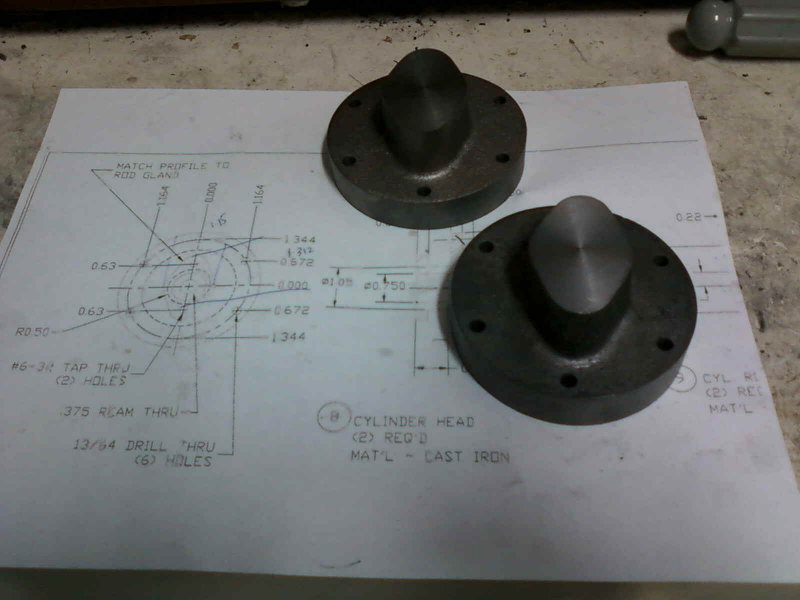
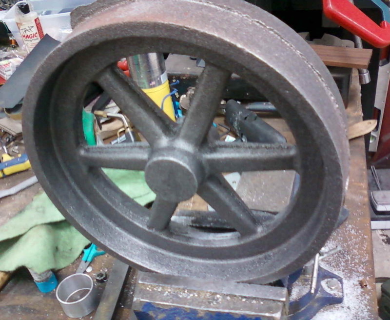
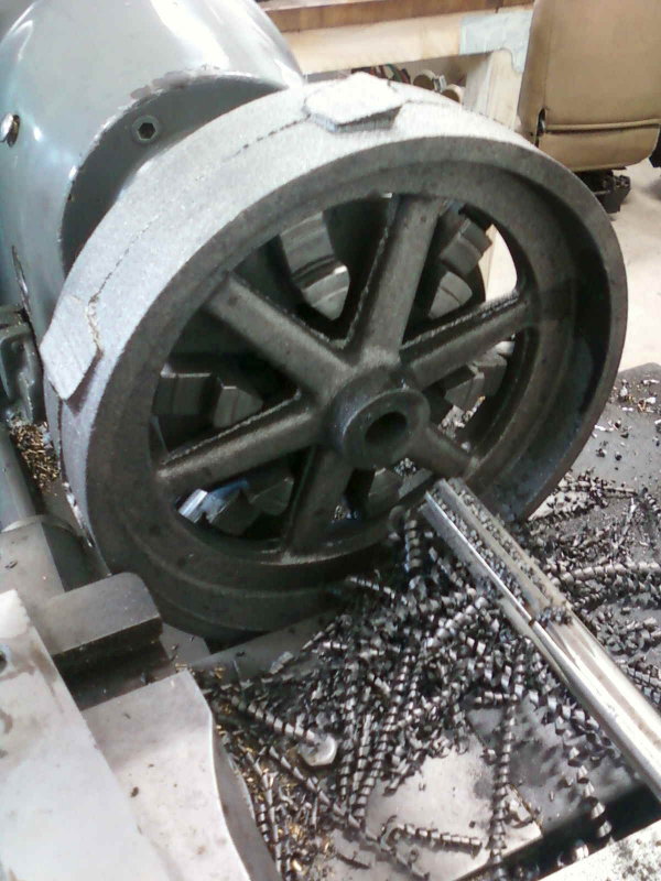
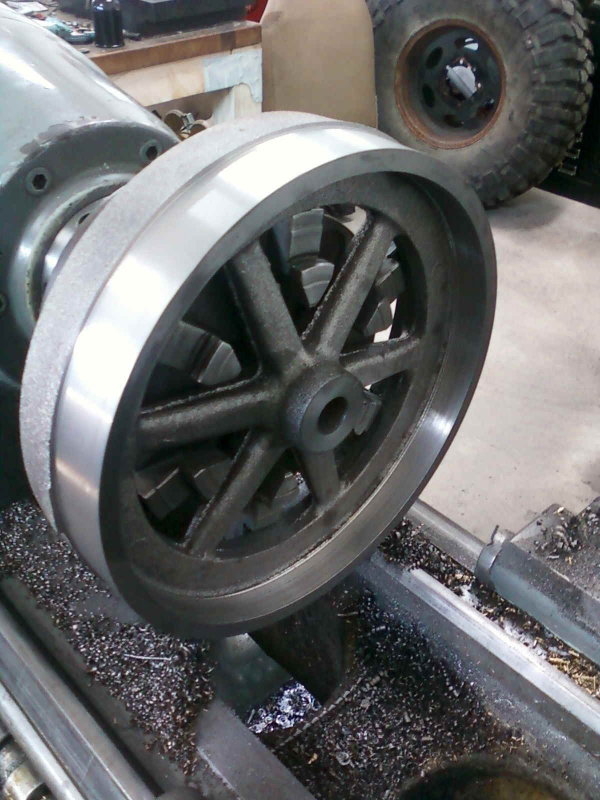
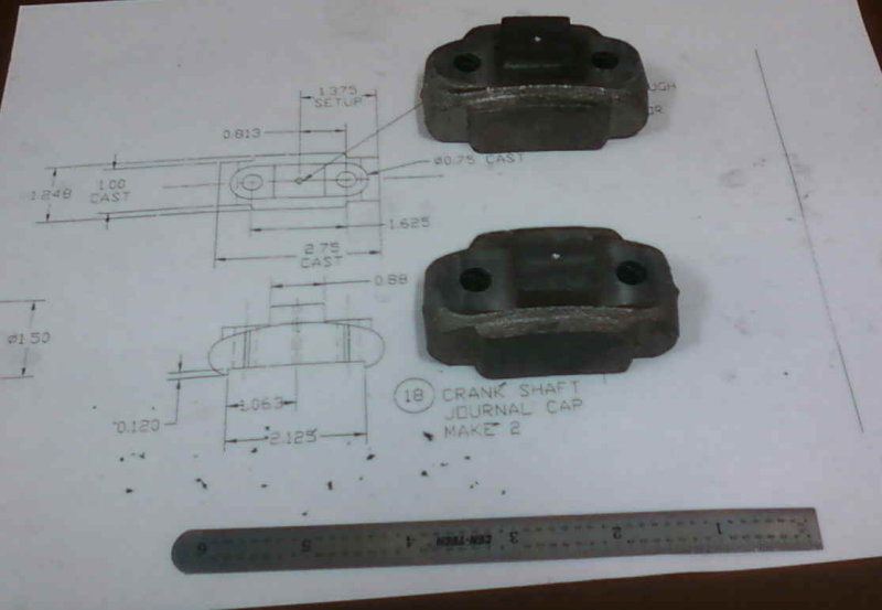
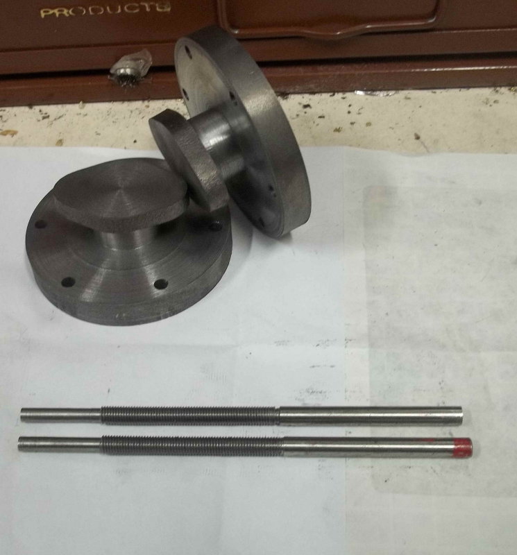
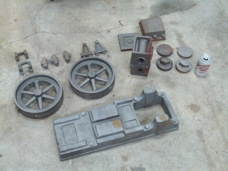
I'll post some photos of the castings a bit later. I'm not sure when I'll start this build as I have a number of other projects to wrap up.
 
I've always admired this engine. I saw it at NAMES some time ago and had often thought it might make a good project when my skills had improved.

I'll be looking in on this project and wish you the best of success in building it.

Cheers,
Phil
 
That is a very nice model. Considering what such an engine might have done in full size, twin cylinders and reversing gear suggest either a (colliery) winding engine or more likely a rolling-mill engine. I don't know what other applications there were for reversing stationary engines. Either way, two flywheels, and crowned ones at that, seem unlikely: for either winding or rolling, a geared drive would be more probable than a belt. On the other hand, of course, there is no rule that obliges you to pay the slightest attention to authenticity.
 
The prototype is the same size as the model, and was designed from scratch by Mr. H. Muncaster. To quote from his article in (March, 1905) Model Engineer and Electrician, "In a sense the engine is not a model. It was made with an idea to produce a small engine that would not merely be a plaything and a source of amusement, but would also be capable of useful work, if required to drive a small lathe, or for any other duties to which it might be applied."

Unpacked the castings for inspection.

large.jpg
 
Took some evening free time to model the conrods in Cubify:

large.jpg


In my view this may be the most difficult or time-consuming pair of parts to make, The bounding box for stock is a 1.5" square bar 10.5" long, or 23.625 cubic inches. The volume of the finished bar is 2.6 cubic inches, so 89% of the material is to be milled into swarf. Not to mention that the fixturing for the various ops. One option that might work better is to machine the U-shaped end separately, as long as there's a way to accurately attach it to the rest of the rod. Probably best to rough it out and then finish so that the cross hole is drilled perpendicular to the rod surface. It might even be best to fabricate as 3 separate pieces.

OTOH I've just reviewed Simon's posts on fabricating his half-scale rods, so following his operation order makes in look reasonable, esp. as with a CNC mill I'll avoid needed any rotary table setups.

I've read about people using Shapeways to 3D print various parts, esp. for casting patterns, so I uploaded the STL file to get an idea of pricing. Printing one of these in steel would cost $350! That would be a last-hope option.
 
Kvom, just leave some useful holding stock and you'll be fine. Trim it back bit by bit and there's no worries. It worked on our compound anyway ;o)


Sent from my iPod touch using Model Engines
 
I'm definitely going to be following this closely - I really like that engine. I think my next undertaking will be a Stuart No. 1, but this is very appealing as well. I may just have to build both of them :)
 
Waiting on other things to make progress on, I decided to start roughing the cylinder casting. There's a fair amount of extra material in all dimensions, so squaring the block doesn't require a huge degree of precision. I used the vertical walls in the sides as a guide and took off the draft material for the top and bottom with a small 2-insert face mill on the Bridgeport. This was not an especially pleasant operation with hot chips flying about, so I've decided to wait until the CNC mill is back in operation to mill the front and back. My intention is to surface grind these 4 surfaces and their mates so that gaskets won't be required.

Today I spent an hour or so grinding the top/bottom to ensure they are flat and parallel. The old grinder still does a decent job as measured thickness on either end is less than .001 difference. Currently 3.407" thick, the final dimension is 3.375. I'll use the top surface as the reference for boring the cylinders, and then machine/grind the bottom at the end.

large.jpg
 
Worked on two more castings the past couple of days: the steam chest and its cover. Working with cast iron is dirty work!

large.jpg


All the mating surfaces are ground, so should seal air-tight without gaskets. Cranking the handles on a manual grinder is somehow hypnotic after a while.

The drawings suggest drilling the chest's mounting holes so that they appear centered in the bosses. Therefore the corresponding holes in the cylinder block and valve plate will need to to located using transfer punches
 
Bit of a problem today as I was squaring up the cylibnder block. Seems to be a bad spot in a potentially bad place:

large.jpg


The cast hole is only 1.25" diameter while the target bore is 2". Nevertheless the bad iron is within the circumference. I'm hoping that it's less than .44" deep, since the boundary of the cylinder bore itself starts that far inside. The outer .44" is slightly larger. The steam ports are in this portion, so drilling them doesn't cause a burr in the cylinder.

My plan is to square the sides and locate the actual center of the bore, the CNC mill a 1.95" hole .4" deep. That should tell me if the occlusion would extend into the bore itself.
 
After some email discussion with Dennis Howe, I have decided to bore the casting oversize and use CI sleeves on both cylinders. An advantage of this in any case is that I can bore the cylinder casting on the mill without too much concern about finish, and turn/bore the sleeves on the lathe where I can a very good finish more easily.

Today's project was simple parts: the rear cylinder heads. They could me made fairly easily with some steel rounds, but the casting set contains two cast "cookies". As a first step, I clamped them in the Bridgeport vise, found a close approximation of center, and drilled the 6 mounting holes. I then made a "fixture" for holding them on the lathe.

large.jpg


large.jpg


Now I could turn the side draft angle square, and obtain the approximate final diameter.

large.jpg


With a good perimeter surface, face both sides.

large.jpg


Screw the two parts together using the fixture and turn both to final diameter at the same time.

large.jpg


Now face to thickness and then reduce the flange area.

large.jpg


Finally, grind both sides flat.

large.jpg
 
Started on the front cylinder heads, which are more complex. First steps are similar to the rear heads. Using the fixture to square up rough dimensions.

large.jpg


large.jpg


large.jpg


All the drilling and boring of the head will take place with it bolted to the cylinder, in order to get everything concentric.
 
Made a start on one of the flywheel castings. They are 9.25" diameter raw to be machined down to 9", and pretty hefty. I figured to use the inter-spoke space to mount on the lathe, so filed down the join lines.

large.jpg


Turns out I needed to use the outer ends of the chuck jaws on the inner surface of the rim. Got it running fairly true and centered after some fiddling, then step drilled the center hole to 11/16" and reamed 3/4.

large.jpg


Then faced the rim and hub, bored the inner rim flat, and turned half the outer rim. No way on this lathe to get the tool to reach the entire width of the wheel.

large.jpg


I figured that with the center hole reamed, I could always make a mandrel to turn the other side, but to my surprise/delight, mounting in reverse and using a bull center in the tailstock to apply pressure, the wheel turned perfectly true. So I did the same ops on the other side.

After removing from the lathe, I could determine the needed finishing cuts to bring to final dimensions. In reality, nothing is critical, but the plans call for the ends of the hubs to be inset from the edge of the rim by 1/8" on each side. I'll do the measurements the before the next session.
 
Yesterday worked on the second flywheel in the same manner as the first. Got this one closer to plan dimensions. Should get some 3/4" drill rod delivered tomorrow to make a test axle and test how true they actually are.

Today I did the basic machining on the two journal cap castings. Simple machining to mill the top and bottom flats and drill the clearance holes for the 3/16" studs. They still need a shallow slot milled in the base to clamp on the crank bearing, but this will be done to fit during assembly.

large.jpg


Almost have my nerve up to start machining the big base casting, as I have a plan pretty much decided on.
 
I've been thinking about how to fixture the conrods for CNC milling, and came up with this:

large.jpg


Starting with a 13" length of 1.625" diameter stressproof steel rod, mill the two 1" cubes on each end, and cross drill the .5" holes in each. With an appropriate fixture block on each end, the stock can be bolted down to expose any of the 4 sides to the spindle.

The steps used to draw the model match the steps needed to machine the part. Once at the stage shown, the blocks on the end can be cut off and the slots on either end milled.
 
I received the raw material for the cylinder sleeves - 1 ft length of 2.5" diameter durabar cast iron. I sawed off two 5" pieces, faced the ends, and wanted to see how accurately I could turn the diameter needing to turn partially from each end. The accuracy of the lathe and the chuck were quite good. When I swapped ends and turned without moving the cross slide, the machined sections matched to less than a thou. So here's a short afternoon's product:

large.jpg


The plan for now is to bore the cylinder block on the mill to a maximum diameter of 2.375" (any larger starts ti encroach on the covers' mounting holes. Then turn the sleeves to a good sliding fit. Then drill/bore the sleeves on the lathe to 2" diameter and secure to the block with loctite. The pistons will then be turned to fit the sleeve bores.
 
Short session in the shop. I was a little tires of machining CI, so decided to turn the piston rods. These are from .375" 303 stainless rod. I got the polished rod figuring that having good tolerance passing the packing gland couldn't hurt. Threads are 3/8-24 and 5/16-18. I single pointed partial threads to ensure straightness, then finished with dies.

large.jpg


I also got polished 1/4" 303 for the valve rods for next time.
 
Some minor progress from the weekend -

Turned the valve rods from 1/4" SS 303 rod, and threaded 1/4-28. Single pointed the threads about 89% and finished with a die.

The turned from cylinder covers/heads to plan dimensions. Used a 1/8" cutoff tool to do the necking.

large.jpg
 
Took a deep breath and decided to start machining on the base casting. Nothing on it is difficult, but accuracy looks to be important. It will also be an expensive casting to replace if I mess up.

It just fits in a 6" Kurt vise. It needs to be sitting level to machine the mounting surfaces, so I compared the vise level:

large.jpg
:

To the top of the casting:

large.jpg


Drilled the 6 5/16" holes for connecting the base to a sub-base, and roughed out the holes for the valve links and exhaust. I will finish the profiles to be symmetric to the centerline once I locate it.

large.jpg


My intention is to do all surfacing, drilling, and tapping on this casting without removing it from the vise. Since the range of holes on the X axis is 17 inches, I made sure the casting was positioned to reach everything.
 

Latest posts

Back
Top