Inspired build of the Benz 1886 Engine

Home Model Engine Machinist Forum

Help Support Home Model Engine Machinist Forum:

This site may earn a commission from merchant affiliate links, including eBay, Amazon, and others.
Joined
Apr 22, 2020
Messages
440
Reaction score
933
Location
Weirsdale, Florida
This is a photo that I found online showing a model engine.
70773-IMG-7820Eweb.jpg
The motor wagon engine has a horizontal flywheel mounted in the rear of the three wheeled auto. It was believed to be the first practical automobile in the world.
There are many sites on line showing the engine and explaining some of the features but very little technical information. All of the videos I have seen are of model engines and many searches have not produced any drawings of the engine. There is a company in Germany that is selling engine castings with plans but that is out of my price range.

So I will just wade right in and see what comes out in the end. All measurements and sizing will be taken from what looks about right in the pictures so who knows what the end product will be.

I had a 5lb weight that I had started machining for a previous engine a few years back but it had many hard spots and several voids so it went in the drawer until now.
I like to use stock that I have on hand to get started as it gives me incentive to continue.
IMG_1942.JPG

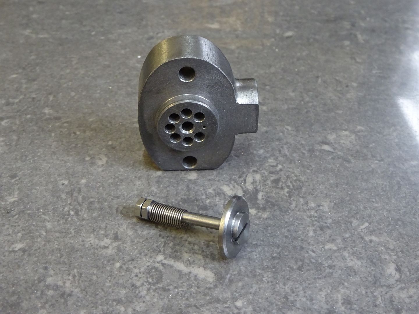
Some more machining, some sculpting, some hole filing, and some paint later.
IMG_1944.JPG

I had this aluminum tubing about the right size and cut off a piece.
IMG_1946.JPG

I whittled it down to this.
IMG_1949.JPG

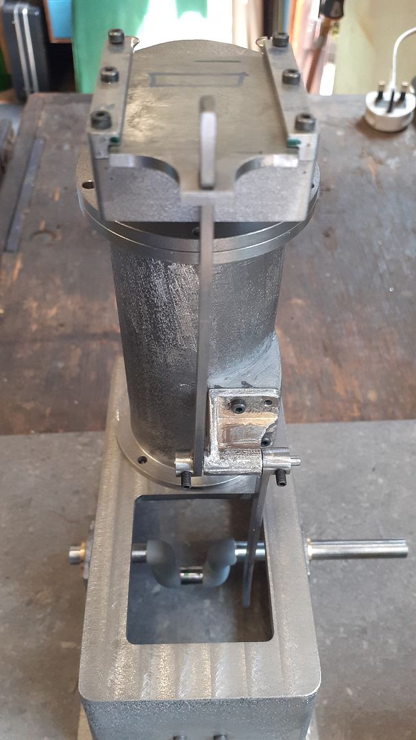
The crankshaft will be attached to open end of this part and the cylinder attaches to the other end.

Thanks for looking
Ray
 
If Benz took out a patent on his engine, perhaps you could search for that. Was it the Benz or the Daimler that was called (in English) "The Patent Motor Wagen"? I like the Benz engine, so I will be following along.
 
One engine I have always liked, same very hard to find any useful info dimensions. Will be following.
Cheers
Andrew
 
The TS version has some short comings and the ready to run engines seem to have copied those so watch out what you use as reference material . One example is the water cooling, on the real engine there should be a pipe from the bottom of the head back into the cooling tank so you get a thermo syphon to circulate the water. Not just a hopper on top like they have. Stroke is also too short and the yoke needs altering to accommodate it.

This site of a replica has good photos that can be used for detail
https://www.vandp.net/sales/729/1886-benz-patent-motor-wagen-replica
I got part way through drawing up a version but it's on the back burner at the moment as other projects take my fancy. You can see the flange for the water pipe on the bottom of the head, correct position for exhaust and the boss on the tank for water return

benz.JPG


benz7.JPG
 
The TS version has some short comings and the ready to run engines seem to have copied those so watch out what you use as reference material . One example is the water cooling, on the real engine there should be a pipe from the bottom of the head back into the cooling tank so you get a thermo syphon to circulate the water. Not just a hopper on top like they have. Stroke is also too short and the yoke needs altering to accommodate it.

This site of a replica has good photos that can be used for detail
https://www.vandp.net/sales/729/1886-benz-patent-motor-wagen-replica
I got part way through drawing up a version but it's on the back burner at the moment as other projects take my fancy. You can see the flange for the water pipe on the bottom of the head, correct position for exhaust and the boss on the tank for water return

View attachment 148144

View attachment 148145
Wow, thank you for that. I adore these very early vehicles and motors and was actually impressed by the ts kit but not any more...
 
Jason that is an excellent web site thank you for the link. It answers one of my questions as to the cooling of the engine. I couldn't see how it would work the way the models have it built.
Do you have any information on the intake slide valve?

Ray
 
If you are making it around the same size as the TS version which is 30mm bore then the port face just wants a slot milled into it about 2mm x 6mm, same for the plate which would be best made from gauge plate (ground flat stock). there are spring under the four nuts that retain the plate with the inlet passage and all mating surfaces want lapping as that is really all that seals the valve.

On the water subject, that connection at the bottom of the cone should have an internal pipe to take the warm water up to the top of the container allowing the coolest water to flow back out the bottom into the jacket
 

Attachments

  • benz1.png
    benz1.png
    459.1 KB · Views: 2
  • benz5.JPG
    benz5.JPG
    62.4 KB · Views: 2
  • benz6.JPG
    benz6.JPG
    85.7 KB · Views: 1
  • benz8.JPG
    benz8.JPG
    257.7 KB · Views: 1
I have in the past had some difficulties getting a regular intake valve to seat properly and there the power stroke is pushing the valve closed. It is hard for me to imagine that I could build a steel sliding plate that is held in position by springs especially against the compression and power stroke of the engine.
What am i missing, are there other examples of this valve?
Inquiring minds want to know.

Ray
 
Similar used on Otto Langen model engines though low compression. many a flame licker uses the same sort of valve but usually without a spring as the valve is drawn against the port by vacuum. Plus all the running examples of the TS model

I've also got IC engines that just have a flat valve on a flat seat rather than the usual narrow angled seat that have good compression but tehn again I seldom get problems sealing conventional valves.

Flat valve and it's valve block, the smaller hole is the propane inlet

DSC02443.JPG


Jason please correct me if I am wrong but after watching the video of the Chippy several times it looks like the valve is opened by vacuum from the intake stroke. If so then the the compression stroke and power stroke would push on the valve and hold it shut.
Isn't that just opposite of the way the Benz engine is operating?

From watching some of the videos of the Benz engine it appears that the springs are holding the valve plate in position to seal the port and the compression stroke and power stroke are trying to push the valve away from it's seat against the springs.
Pictures of other model Benz engines have 8 nuts on the intake housing. Four nuts are to apply pressure to the plate with the springs between them and the outer four nuts nuts to hold the springs on. Maybe that is to keep the back four nuts from loosening.

Please help

Ray
 
I am making one of the TS engines and as Jasonb says there are a lot of shortcomings. The one thing that helps with the valve sealing is the very low compression ratio. less than 2.5:1 However I am raising the compressino ratio on mine and I still expect the valve to seal. All surfaces are lapped, the link gives positive movement and it is well lubricated. One of the other liberties taken with the TS model is the camshaft rotation is reversed so beware of that if you are looking at models on you tube for example.
 
Yes the compression will push that valve onto it's seat of the X-Type. I was showing that a flat valve can seal reasonably easily.

As Tony says the compression ratio is low as is the size of the inlet port so the springs just need to be strong enough to keep the plate onto the face, any more and you start getting unwanted friction. The TS general arrangement would seem to just show nuts with no springs but the images and link I posted earlier all show a nut with knurled flange that is used to compress the spring and provide some adjustment of spring tension, this is common on most of the early engines that use a sliding plate

This is an engine I'm part way through, although it is a flame sucker there is still quite a lot of resistance if you try and turn it the wrong way when the compression IS trying to lift the valve

20220703_132812.jpg
 
The crank shaft is done and painted.
IMG_1955.JPG

I decided to make it with a 2" stroke and with a needle bearing for the rod journal. Tapered steel pins were installed through the web shoulders and at the rod journal for added strength. I am happy to announce the crank runs very close to true after cutting out the center part of the main shaft.
IMG_1960.JPG

The flywheel looks a little small for this size engine but I won't change it now rather I will keep this in mind during the rest of the build so a larger one can be changed out later if needed.

Thanks for looking
Ray
 
I wanted to check for any interference problems now before I go much further. Made up part of the connecting rod and the inner liner in order to check. It looks like there will be no problems or maybe just minor issues.
IMG_1970.JPG

IMG_1972.JPG


The cutaway part of the liner is the space for the cooling water.

The liner won't be installed permanently until the holes for the water connections are done.

Thanks for looking
Ray
 
Some more progress.
Cleaned up and installed the cylinder mounting bracket.
There will be another mounting point with a ball bearing under the crank shaft to support that end.
IMG_1983.JPG
Drilled the holes for the water cooling lines and installed the liner.
IMG_1984.JPG

After the Loc-tite cures I will cut the cylinder down even with the liner.

Thanks for looking
Ray
 

Latest posts

Back
Top