A Table Engine Tale

Home Model Engine Machinist Forum

Help Support Home Model Engine Machinist Forum:

This site may earn a commission from merchant affiliate links, including eBay, Amazon, and others.
This is difficult :-[.

It really is very nice of all of you to say such nice things and perhaps a mite rather embarassing particularly as I'm very new on the block round here.

I can only say - I just love making models and have done so for most of my 67 years and do love to share the outcome with anyone that is interested. Model making in various forms and interests throughout those years has always figured high on the priority list despite having a varied career - and one which model making has certainly 'interfered' with at times. I guess it would be fair to say that apart from my long suffering but totally supportive wife Sue it is my overiding passion on a day to day basis.

Before being able to be part of something like this on the ME forum and recently on here it was very much a case of the odd occasion on a 'Bit's and Pieces' night whilst a member of the NDSME and laterly once a year at the Forncett Steam Museum's Model Engineers Day Out. I've always believed, that as a member of any group, you will only get out what you are prepared to put in. Forgive the patently obvious but on here it can be done daily and the contact for all concerned is such an asset to our individual take on the hobby.

I really don't see myself as anything other than someone who enjoy's his modelling and am well aware of it's limitations. When I see the work of others on here and elsewhere I can only marvel at their ingenuity, their dedication to the task and their abilities. It is all relative between each and every one of us but all to a common cause.

Over many years, no doubt like so many of us, I have seen some truly stunning models at exhibitions. I have always tried to allow that to influence my thinking - not always on a try to do likewise and certainly not to try to 'out do' but to just try to do the best I can and improve a little each time. Perfection, like beauty, is definitely in the eye of the beholder. It's how you use it that's down to the individual.

Hope you can see where I'm coming from and that you won't see that as anything other than sincere :)


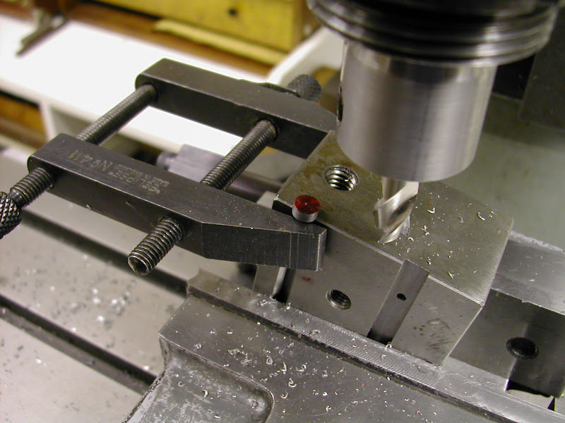
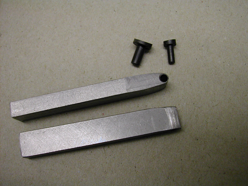
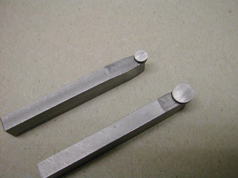
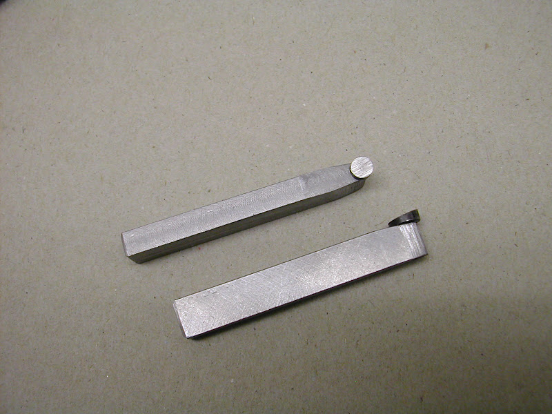
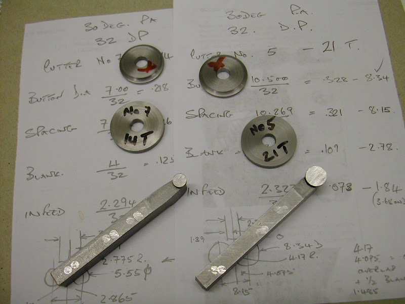
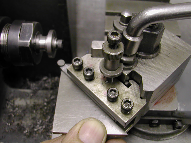
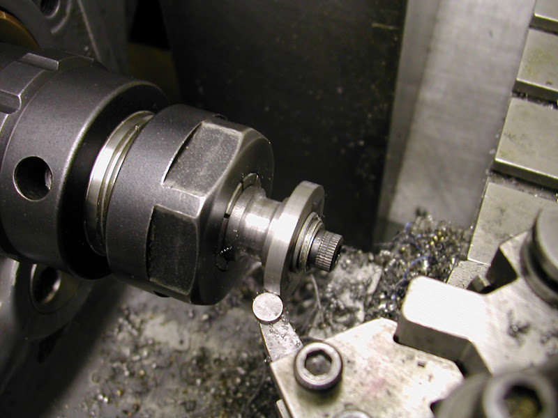
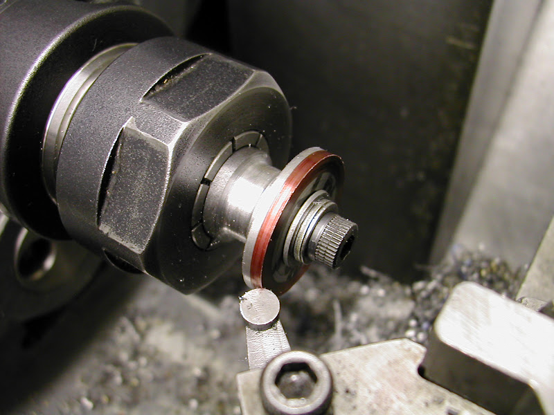
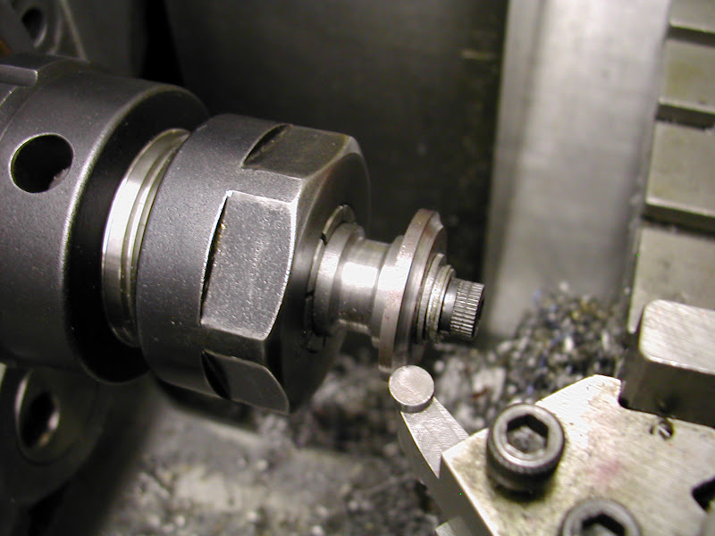
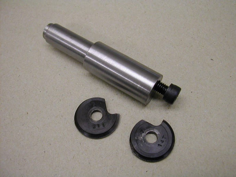
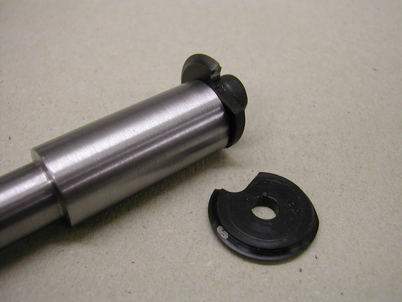
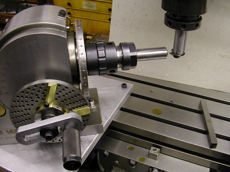
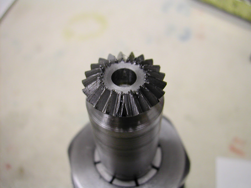
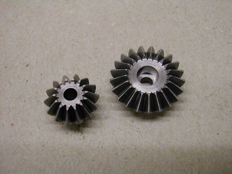
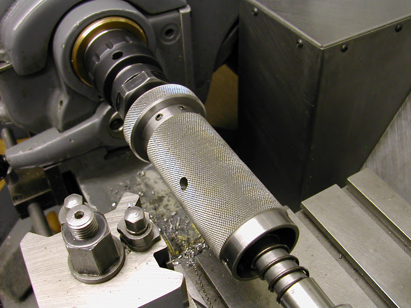
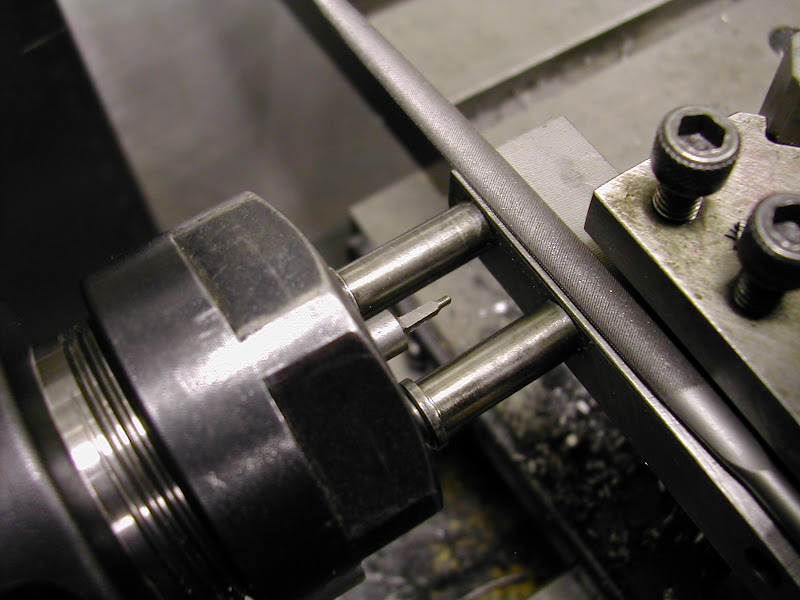
Nothing much to report - it's been a long, not quite but almost, non-workshop day with a visit to the enemy, sorry - mother in law taking precedence but I have made a start on the tooling for making the gear cutters tonight.

Andy, in the New Year you'd be more than welcome to come over and have a 'mardle' (That's Suffolk slang for chat for you non 'Suffolk Boy's') and see whats doing - I'll get the kettle on ;).


Kind Regards - Ramon
 
That is looking truly amazing Ramon! :bow:

Dave
 
Ramon,

While I appreciate modesty, you need not be embarrased by any compliments. This is all top notch work, and is easily equal to the best that others have offered up. Not only a first class build, but excellent writup, combined with good photos to illustrate your points.

I've also learned a couple of things along the way (notably the part of making pinned joints invisible), and that's worth a world of praise. Keep up the excellent work!
 
All the little tips and tricks you use for your own convenience are something that the rest of us may have never seen before. I've learned something from almost every post you've made so far. The quality of the parts you're making is outstanding and the pictures of each setup are much appreciated.

Ray
 
Ramon, please do not feel embarrassed about what is being spoken of your work. It is a testimony to the appreciation of a well thought out execution of building skill. To you, such things may seem to be mundane or nothing out of the ordinary, and perhaps they are, but nonetheless, the final results are truly amazing. I really enjoy the visuals that show how something is set-up, followed by the steps to the end result the most. Seeing just the 'after' images takes away from the impact of what is required in fabrication. That governor assembly is terrific and it has shown me a couple of nuances that I had not considered before. Continue to do what you do and do not let us influence your doing so.

BC1
Jim
 
Only just glanced at this post for now ,and was most impressed,will have agood read later.
something to look forward to.
Thanks Don
 
Hi Guys, Just an update before Santa gets here.

The last few days have seen some ups and downs which have had a considerable influence on productivity ::)

Ah well, theres always tomorrow - tomorrow ??? ??? ???

As mentioned before, gear cutting is a new procedure for me. Many years ago, during training, a helical spur gear was cut on a universal mill along with a couple of straights but they were exercises and were of different DP so nothing meshed. This would be the first time on all fronts - home workshop, making tooling, making cutters, cutting the gears and getting them to work.
I'm pleased to say apart from one or two hiccups on 'yours truly's' part the whole thing has gone much better than expected and tonight saw the two gears temporarily fitted, meshing and revolving well without binding.

I took some pics along the way - I would stress though that they are not, most definitely not, intended to show anyone how to do it, but just to show those who, that like me before I began, may be considering the prospect of having to make some with a bit of cautious reserve.

I did not particularly want to delve into theory and calculations more than I needed to so kept my study as low key as I could. Just sufficient to get the job done was all that was really needed

I referred to the information set out in the Ivan Law book regarding the layout of the bevels and also the information on making the tooling for making the cutters. However I found a copy of an article from Model Engineer tucked away in a folder which gave a little more info on making the actual tooling so decided to use that.

This is how it transpired.......

It was thought that instead of making the turning tool to cut both sides of the cutter at once that a single cutter would be easier to control and by turning the blank round would put the centre of the form exactly on centre line. Two tool holders were milled from mild steel and the ends milled off at a 5 degree angle and drilled though square to that face to take the tooling buttons. The buttons were turned from silver steel and set up on the mill (that block again) and the tops milled off at a 10 degree angle. Heated to a bright red and quenched in oil they were left untempered for maximum hardness. The tops were then lapped with a diamond lap and finally stoned
DSCN4047.JPG


DSCN4052.JPG


DSCN4054.JPG


DSCN4058.JPG


Notes were made for each cutter but this was where the first hiccup was made. The blanks were held on a mandrel and a facing cut was made to '0' the cross-slide. Afdter setting the cutter off to one side the cutter was then fed in the required amount. Looking at the very small and obviously wrong form it took some while for the penny to drop that the infeed was from the point of contact not from the previously set '0' :Doh:
DSCN4061.JPG


Also noticed at this time was the instruction in the book to rotate the buttons at 45 degrees facng inwards to present the fuller form to the blank. It was too late to do this as the buttons were loctited in so the tool holder was rotated at the required angle. Actually this is probably best as this way it can be angled from both sides if required.
DSCN4063.JPG


Once again a facing cut was made ........
DSCN4066.JPG


Then the blank was inked up and the cutter - set at the correct side offset - was brought in to just touch on then the dial was zeroed ::)
DSCN4068.JPG


This time the form looked correct, the blank was removed and turned over then the tool taken in to the same setting.
DSCN4070.JPG


I'm going to have to stop here as I have just noticed that some images that should follow have gone astray - back with the final few pics and hopefully a finished govenor a while later then but in the meantime......

Merry Christmas to you all - have a great day tomorrow and enjoy the festivities.

Regards for now - Ramon


This is great stuff. Keep it coming. :bow: :bow:

Ron
 
Merry Christmas Ramon,

I have the ME article you speak about. I think your approach is a far better one as getting the profile centered is a very important feature to cutting good gears that don't "lean". The only real way to do that is to measure the thickness of the cutter and set it to center height minus half the thickness of the cutter.....if the form is not dead center...you'll have a real tough time getting the form on center....and it becomes somewhat guess work.

Your approach should guarantee the form is on center unless your form tool wears significantly.

Additionally, not drawing the temper of the cutter is a smart move.. they are far too small to have any significant internal stress that would warrant tempering, and the edge will be tempered just by using it. Leaving then full hard will allow for a very keen edge.

:bow:

Regards,

Dave
 
Hi again guys, Merry Xmas (it's still the 25th here but I have managed to escape)

So keen I was, to relay the latest 'saga' that I omitted to say thank you all for your encouraging words. I am beginning to realise just how much most of you appear to view this extension to our hobby - they are much appreciated and I'm glad that you find this useful and of interest which makes it all worthwhile. Now let's get back on track.......

Dave - the idea to use a single cutter came from a reply I had on the ME forum (thanks Neil) - a reference to the fact that double cutters have to be exactly square to the blank and can create chatter. It seemed more practical to just use one and by turning the blank around ensure centrality. The chart showed two differing thicknesses for the blanks depending on the cutter number. If I were to do it again I would make all the blanks the thickest dimension so that once set up on the centre line this would not have to be changed. Obviously the thinner cutters would need reducing on their outer areas to the correct thickness as shown in the relevant charts. The blanks were made from slices of Silver Steel -from a bar of 1-1/4 diameter which I bought in my first year of model engineering - 1972. It has sat under the bench since then just waiting for a job :-\ There was a shop called 'Disposals' that sold all kinds of surplus material, mechanical and electrical and literally thousands of nuts and bolts. I think I paid about five shillings for it - 25p - hate to think of today's cost

After the first two didn't quite make the grade the second pair came off ok. An arbor was made with a 6mm tapped hole offset 3mm and the blanks milled to form a single point cutter. As you say there seems little point in tempering such items, they are not destined for long hard work and the likelyhood of chipping is far outweighed by the extra hardness. Though I do have cutters that have been tempered it really isn't neccessary for such low key use
DSCN4114.JPG


DSCN4116.JPG


The dividing head - this was it's first use in true dividing mode - was set on a sub plate to get the travel past the cutter. The main gear was tackled first. The gears were cut using thee parallel depth method, the cutter set to depth and the gap formed in one pass, winding the cutter back and forth a few times to 'clean' the surface.
DSCN4095.JPG


Some how the calculator went awry and gave a wrong reading for setting on centre height. Confident it was correct I didn't check and milled what looked like a hypoid gear :eek:. next attempt saw a loss of direction and a total cock up after five teeth and the third attempt went fine - until that last cut :eek: :eek: when it cut through the first tooth. It took some time before it was realised I'd made the classic mistake of counting the hole it started in as '1'
DSCN4096.JPG


Undeterred but beginning to get a bit anxious that one would ever materialise the fourth attempt went ok
DSCN4103.JPG


While it was still in the collet chuck it was deburred with a needle file and the outer tops of the teeth rounded slightly.
DSCN4104.JPG


With new found confidence next up was the pinion.Leaving the head set at the same angle this was cut in the 'X' axis as opposed to the 'Y' axis for the main gear
DSCN4106.JPG


And the finished result - my first gears ;D Trial assembled on the governor and just running free they appear to mesh and run well without binding but will they when everything is pinned and fixed? That'll have to wait a bit to see.
DSCN4109.JPG


I'm not unaware that on the scale of things many have made far more esoteric gears at home than these but these are my first and I'm well pleased with the outcome. I have always baulked at the thought of doing them in the past having bought them when required but this bodes well for future projects..

If you've never done it before I hope this will prove encouraging.

Regards for now - hope you had a great day too

Ramon


Well done Ramon, they certainly look upto the job, next time get them done before you start on teh xmas sherry and you will get them right first time :D

Fancy knocking out a couple of skew gears for my Benson while the dividing head is out ;)

J
 
Hello Ramon,

Congratulations on your first set of gears. Very well done. I too am thoroughly enjoying your presentation of this project and have also learned quite a few new things along the way. Thank you for taking the time to share your work with us, it is greatly appreciated.

Could you please provide the issue(s) that the gear cutting information using the button cutters appeared in Model Engineer? I have seen the technique before, but haven't found a source for the mathematical information to be able to make the tooling. I would really appreciate the dates so I can track down the article. Thanks again.

Kind regards,
Mike
 

Now theres a thought Jason ;) ;) Actually do you have any idea of any articles on cutting such - with 'simple' kit that is.
Having said that I think a restriction for me however would be not being able to tilt the mill head nor have the room under the spindle with the DH tilted up to get anywhere but that said a new mill may be on the cards in the New Year - depends on how things work out.

Mike - the article I referred to was one by D.A.G. Brown which was featured in the Sept 2nd 1994 issue of Model Engineer. Let me know if you have any difficulty finding it as I can pass on any info from it you need. It explains the requirements of making tools for the relevant cutters very well and gives full charts for doing so for 14-1/2, 20 and 30 degree pressure angles.

The governor was assembled with the gears pinned in place this afternoon and it works very smoothly. It was stripped down again for two small refinements so no pics but hopefully some a bit later.

Had a nice find this afteroon - going for for a 12 BA die in it's usual storage tin found not only a 14 BA but a 16 as well - didn't even know I'd got 'em. Isn't getting old fascinating ;D

Regards - Ramon


Nice job on the gears Ramon - always a buzz to get a set working properly - I well remember the first set I did - after two attempts!


rvgov2.jpg
 
I have just uploaded to the downloads section an extract from an old freebie download book that shows and explains the way to cut a bevel gear.

Hope it helps to explain a few things.

If you want the full book on bevel gearing, it is 7mb in size, so I don't think it would go by email, but if you have Skype, if you contact me, it can be transferred while we talk.


John
 
Ramon, nice gears I have to give that a try very soon.

The book John just posted a bit of is Machinery's Reference Series No. 37 by Ralph E. Flanders 1910. I have a copy but there should be a google version.

Dan
 
Ramon, thanks for your interesting post - I've cut gears before but it wouldn't have crossed my mind to use a single tooth cutter - they look really good.

Must try it myself sometime.

Ken
 
Hi guys, I had intended to be able to do this last night but things didn't quite go as hoped for.

First off thanks for your responses both on here and by PM.

Tel, good to see you are still keeping an eye on things - that's a nice set you have there and an impressive looking bracket - cast or fabricated?

John, thanks for the offer of the book but I do have sufficient for my needs on current projects - though I would like to take a look at the section you have down loaded. However, I may be missing something or doing something wrong but couldn't find the 'Download section' you refer too - is this is under the 'Plans' header

Ken, I don't feel that a single point cutter would ever match a properly made and backed off conventional one for continuous or high volume use but this did work fine albeit a bit slowly due to the intermitent cut and low cutting speed. It certainly works in a situation like this where very little is required of it task wise ie just two parts. The cutters exhibited no wear though and look virtually unused.

Well, at last the governor is complete and fitted in place. The small refinements referred to previously were to make a new bronze top bush for the standard with a slightly (.15mm .006" )thicker top flange to lift the pinion a tad. The weight of the parts above were pushing the shaft down causing the pinion down onto the gear just a fraction too much. The second thing was to make a stop to restrict the outwards arm movement. To keep this reasonably in scale it required a small bolt and as such I've just turned the smallest item I think I've ever made...a square headed 14 BA bolt about 2.5mm long. I expect that may be big by some standards but it's certainly pretty tiny to me :D

Here are some more pics.....

This is the bolt for the governor stop. The nut is a standard 10BA for comparison. The find of the 14BA die was somewhat opportune to say the least.
DSCN4129.JPG


With regard to threading and just as a matter of course this may be of interest .. many years ago when I bought my first sets of ME and BA taps and dies like most I made a tailstock die holder to use them in the lathe. Bought at an ME exhibition these were carbon and relatively cheap . It soon became apparent that some of the taps cut larger holes and some of the dies cut undersize - one was so bad that it literally reduced the size of the material rather than cut a thread. A call was made and the sage advice offered was to open them up by tightening the expanding screw. Well, it doesn't take long to realise that you can't exactly do that witha tailstock die holder - if the reccess is big enough to allow the die to be expanded it must inturn put the die off centre! Hmmmm ??? However if the die could 'float' then it may solve the problem. I have never seen this problem referred to nor indeed this 'solution' but some may find something in it's value

By making separate flat die holders that could be 'backed up' by the existing tailstock die holder in order to keep them square, but which would have no influence on them other than pressure, solved the problem without having to source better quality dies.

In virtually all instances except that one bad die these have enabled threads to be cut with those original dies with controllable degrees of tolerance of tightness. The die holder, still there - just in case - has never actually been used in the manner it was intended since but purely as described.

In use the tail stock die holder, which is spring loaded to present a degree of forward pressure to the floating die holder and maintain squareness as the thread progresses, is brought up to the the FDH and the FDH rotated by hand or held stationary as the chuck rotates if done under power. Most threads up to around 1/4 can be cut by (my) hand grip/torque alone and of course the smaller they are the more sensitivity you have on the cutting - in fact the holders are, if anything, rather heavy for the 14BA thread involved here to get any real feel but with care it did the job.

These are the holders and blanks made some thirty years ago. There are in fact even more blanks as it was intended to have individual dies fitted ready to go - obviously that idea never got very far and the three you see are all that have been used over that time. They are easy enough to make, the only criteria being that the back face must be parallel with the face the die sits against. The die holder on the right is the original made at that time too.
DSCN4153.JPG


This shows the holder in use, in this case the TDH was brought very gently into contact with the FDH and the FDH rotated with thumb and forefinger in order to achieve a degree of feel. This was virtually negligible given the weight of the holder to the size of thread!
DSCN4119.JPG


DSCN4121.JPG


After threading the square was put on using an adjustable filing support
DSCN4125.JPG


And finally, with a finial turned for the top it was all finished
DSCN4131.JPG


And bolted in place ;D
DSCN4140.JPG


DSCN4150.JPG


Another stage is complete then - next is to sort out the steam inlet and throttle valve linking it through to the governor and the exhaust pipework. Hopefully that will not take too long - but I still haven't decided what colour to paint it :-\

As always thanks for your interest and input

Regards for now - Ramon


Ramon,
Thanks for the photos of your floating die holders. I made a fixed one many years ago but your system is much better.

The download section link is in the menu section directly below your avatar photo when you are logged in to the forum.

Dan
 

Latest posts

Back
Top