A Table Engine Tale

Home Model Engine Machinist Forum

Help Support Home Model Engine Machinist Forum:

This site may earn a commission from merchant affiliate links, including eBay, Amazon, and others.
Ramon,

Thank you for sharing your project. I have been following it with great interest and have learned some very interesting machining techniques from you. Keep the postings coming!!

Harold
 

Hi guy's - once again thank you all for your interest and your most kind comments. Coming from such stalwart posters and excellent machinists I can tell you, they are valued indeed and much appreciated

With regard to the video Ray I hope you won't be disappointed if I'm not able too but so far I have had no luck on my previous attempts to post a short clip of the IC engines running. That said I will try again as obviously it is something I'd like to get to grips with.

I haven't had a very good day today so reading this has cheered me up no end. I'm glad it's proving helpful and will post some more within a day or two

Regards for now - Ramon
 
I'm not sure what kind of oiler would be fitted to this kind of big end - I'm considering an oilbox attached to the rod with a thin pipe leading into the top of the bearing - Anyone any thoughts on this?


That would be in keeping with good practice...make sure it's in a place someone would actually put it. I wouldn't want to climb under the entabulature on the real engine to fill the box if the engine was running ...for instance ;D

Dave
 
Hi Dave - yes I had considered that fact but don't forget there was little if any H&S in those days :eek:. From the text of the design it would appear that these were quite small engines even in the larger size so I guess reaching in whilst it was running wouldn't have been too risky. I can't think of any other way other than the rotating arm type with a pick up from a stationary oil resevoir as on many large horizontals but I think that would be out of keeping for this type and period - that's an assumption though so am open to any further knowlegeable input.

Things have been a bit slow but progressed a little never the less......

After those small bearing blocks the valve rocker arm was tackled next. This was made from some steel that was used at work - 'UHB11' which is a bolster steel, apparently similar to En9 and machines relatively easily. It's great virtue is no matter how much sections are removed it has virtually no distortion unlike most BMS. Despite the apparent rough machining marks it files and 'emeries' to a reasonable finish quite easily too.
DSCN3798.JPG


Next op was to mount on a mandrel and turn the bosses and face each side
DSCN3799.JPG


Then on to the rotary table to radius the end, relieve the sides and finish the front end
DSCN3804.JPG


DSCN3805.JPG


Initial cleanup improved matters
DSCN3808.JPG


Next up was yet another radius form tool and a taper reamer for the Rocking Shaft Drive Arm
DSCN3843.JPG


The tapered hole being reamed in the drive arm before turning to ensure squareness. Even now after so long messing about with these things if there's one thing that gives me a real buzz from this hobby it's when a simply made cutter that you've made yourself works well.
DSCN3811.JPG


Finished arm, the lower hole was tapped 6BA in situ on the lathe as for the reaming
DSCN3835.JPG


The shaft was split with one part loctited into the other after the arm was slid on. The whole was then assembled in situ and the arm loctited in alignment with the lifting shaft and over the join to disguise it. What appears to be a bad pinning attempt is actually a 'ding'. This will hopefully dissappear when it is eventually pinned ;) The tapered end was turned at the same topslide angular setting as the tapered reamer to ensure matching tapers
https://lh5.googleusercontent.com/-aFoGiINE-EU/TtVNSTQy-bI/AAAAAAAAFj4/9cLXpwHM1J0
/s800/DSCN3836.JPG

And finally it's ready for those last three 'eccentric' parts essential to make it run
DSCN3841.JPG


The eccentric itself was made today in an easily made fixture but I think this enough for this post so back with a bit more on that a little later .


Regards for now - Ramon
 
Hi Dave - yes I had considered that fact but don't forget there was little if any H&S in those days . From the text of the design it would appear that these were quite small engines even in the larger size so I guess reaching in whilst it was running wouldn't have been too risky. I can't think of any other way other than the rotating arm type with a pick up from a stationary oil resevoir as on many large horizontals but I think that would be out of keeping for this type and period - that's an assumption though so am open to any further knowlegeable input.


Well two trains of thought come to mind

1. Long spout on the can keeps the "bits" away...good way to lose a spout
2. As someone who's reached into said spaces on marine applications...I mightleave it there....or I might move it... ;D

I would vote for the first one in this case I think.....

Mighty fine job of it I might add! :bow:

Dave

 
Hi again guy's,
Following on from the previous post here are a few pics of the method used to turn the eccentric which some may find interesting if not useful.

First off the eccentric blank was turned to finished OD and the groove for the strap put in finishing the face opposite the boss. No pics of this I'm afraid.

Next up a fixture plate is required. This one was from a previous IC project. It requires a hole for the blank, a slot cut through and drilled and tapped for a clamp bolt. The two edges opposite the slot need to be square to each other.
In this shot it's being set true on the faceplate using the nose of a drill chuck as a centre. It wasn't clocked true as any slight discrepancy can be taken up when setting the valve. The finished size hole for the eccentric should only be done once in situ on the lathe.
DSCN3815.JPG


Next a stop bar - in this instance a parallel - is clamped spaced the amount of throw required from the end. Here a 5.3 drill was used
DSCN3816.JPG


The hole was then bored to receive the eccentric with a nice snug fit
DSCN3818.JPG


A lower stop bar was clamped for the plate to slide on and another parallel clamped for balance
DSCN3819.JPG


The clamps are released, the plated slid over to the stop and re-clamped. It's ready to use.
DSCN3821.JPG


The hole is put in first - drilled, bored then reamed - that way if the part should move when turning the boss it can be held on a mandrel. I choose to rough turn the boss still in the fixture - the only tool suitable to clear the clamps was a boring bar hence the need to do this op in reverse
DSCN3824.JPG


Initial turning complete and ready for finishing off on a mandrel
DSCN3825.JPG


Another previously used expanding mandrel was recycled and turned to fit the bore
DSCN3828.JPG


Then the boss and adjacent face was finish turned. As said the groove was turned on the initial blank, the fixture clamping only on the thin far edge and about 1.5mm on the area next the boss. The pressure achieved by these clamping plates - and the expanding mandrels for that matter - is considerable given their simplicity.
DSCN3829.JPG


Transfered to a dividing head on the mill the clamp bolt holes were drilled and tapped and it's ready to fit
DSCN3833.JPG


Well, as said, I hope that's of interest, even useful for someone. If it's 'Teaching Granny......' then my apologies.

As alluded to earlier this derived from the need to offset IC engine backplates for turning the intake tubes. Once the plate has been made it's very quick and easy to set up and of course its repeatable. Damn sure beats the hell out of using a four jaw ;)

Had a long day in the garden today but did get a tentative start on the strap tonight - a bit more later then

Regards for now - Ramon
 
Nice faceplate demo Ramon! A man after me own heart....love faceplates!

Dave

 
I enjoyed the explanation and pictures. Hope to remember some of your techniques when I make something like this. Thanks!
 
Ramon, I have been, and do like your style. A very well documented build with clear photos and concise descriptions. Nicely done. It will be glorious to see this engine running, I for one am waiting in anticipation of the video.

BC1
Jim
 
A very interesting way to do eccentrics. Now I have a reason to knock the dust of my faceplate ;). As usual another well documented post.

Ray
 
Hi Guy's glad it's been of interest. The more I use clamping plates and expanding mandrels the more I like 'em. They really are an excellent work holding device. It's much easier for instance when doing a cylinder to just concentrate on getting the bore right(and one end faced if doing it in the chuck) then set it on an expanding mandrel to do the other end as well as to move it to the mill and bring all the faces to the bore. I'm convinced it's much easier to keep things under control this way than to try to get the bore in relative to external faces after they've been machined.

Had a really good session today and took quite a few pics of making the eccentric strap ......well you did say you like piccy's ;)

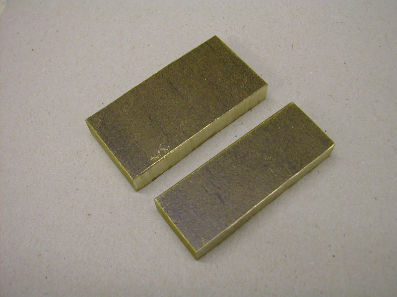
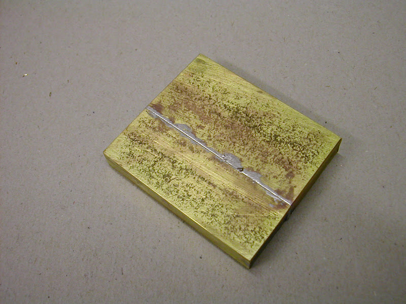
First up was a couple of pieces of brass - this is actually manganese bronze which machines well giving nice chips as opposed to spraying those razor sharp shards everywhere that you get off some brass.
DSCN3847.JPG


The long edges and one face on each piece were milled then they were treated like the small bearings previously mentioned and soldered together in exactly the same fashion. (Size of this is 52 x 48 x 9 mm)
DSCN3849.JPG


The block was then milled flat on both sides before drilling and reaming a .250 dia aligning hole on the break line and four fixing holes
DSCN3850.JPG


DSCN3853.JPG


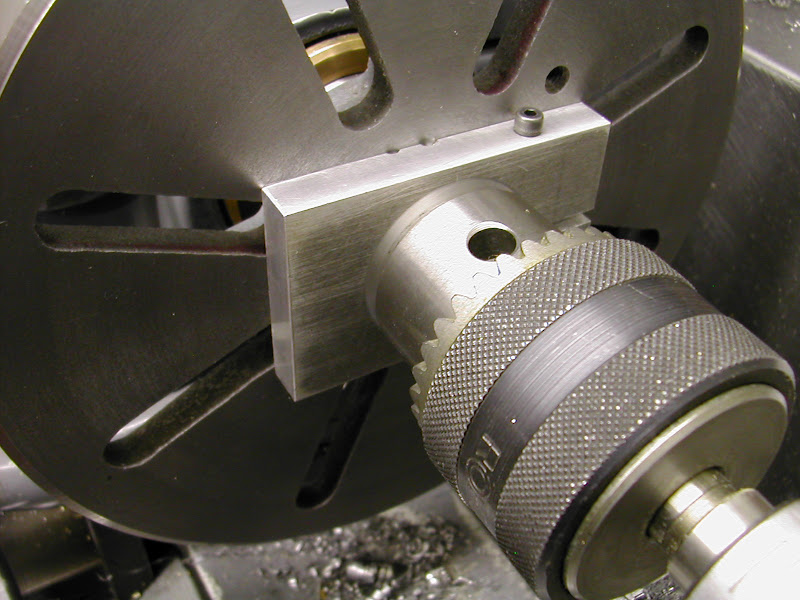
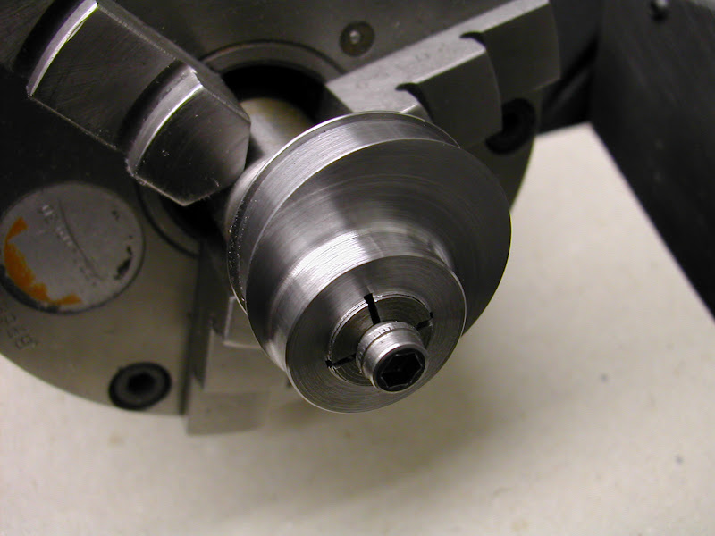
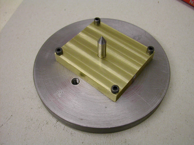
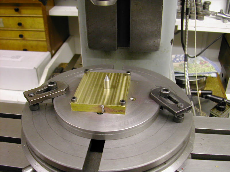
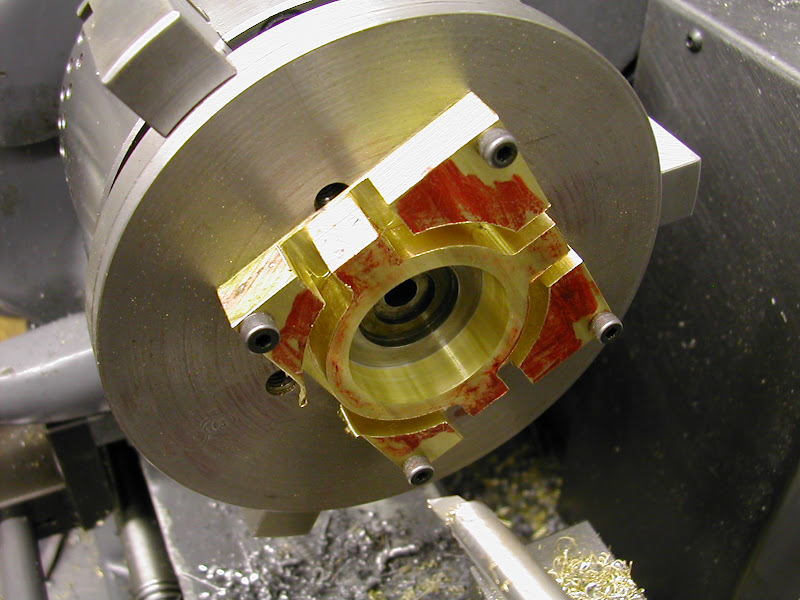
It was then bolted to that small 'faceplate' seen earlier. The spigot is aligning it in a central hole
DSCN3855.JPG


The rotary table was zeroed and the part set square to the mill the spigot now aligning the faceplate to the R/T
DSCN3858.JPG


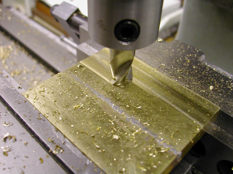
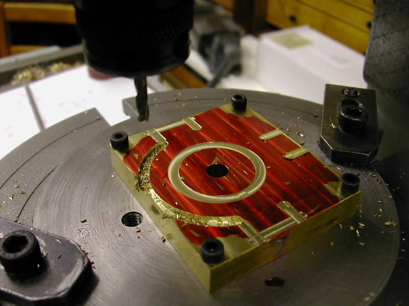
The coordinates were checked by cutting in a couple of thou then the lower form was cut first. The R/T has stops fitted which makes for much less anxiety about over shooting :)
DSCN3860.JPG


The cut line was done to finished dimensions but the roughing out was done using a 3mm cutter with the finishing done with a 4mm.
DSCN3864.JPG


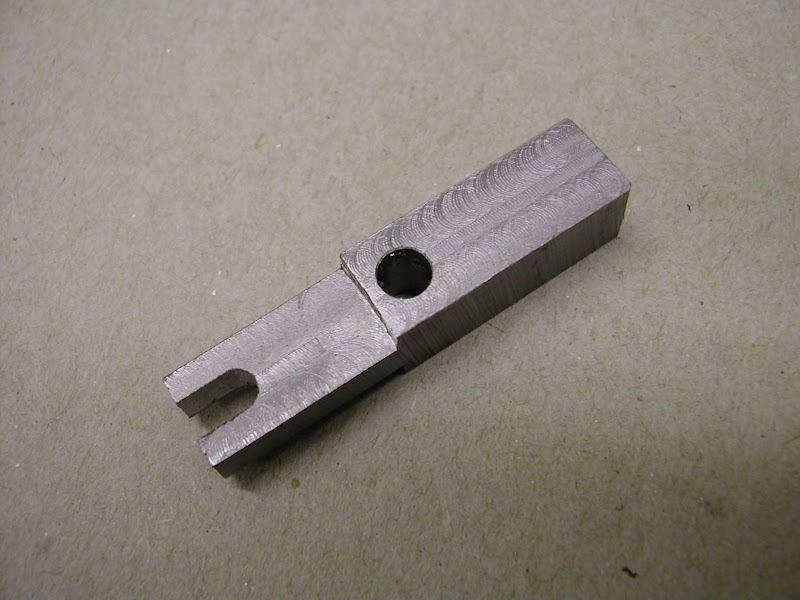
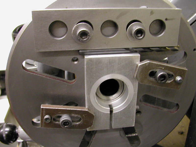
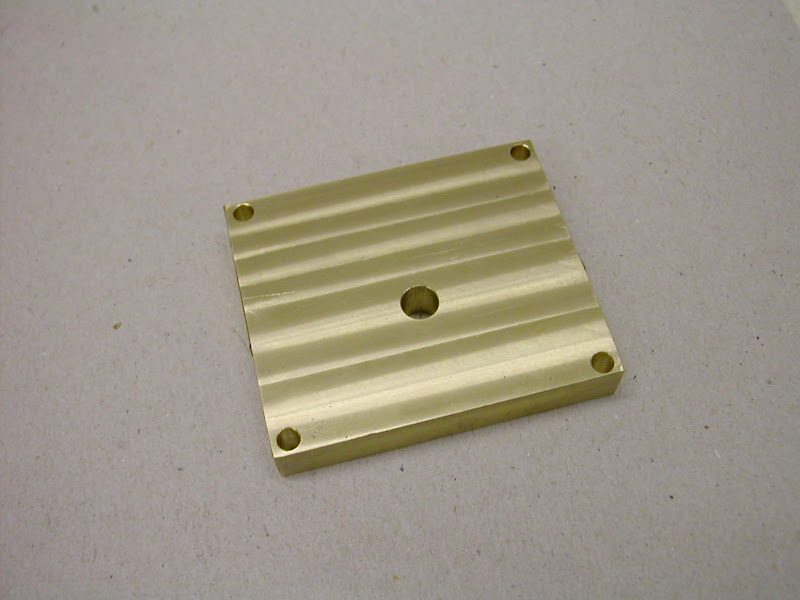
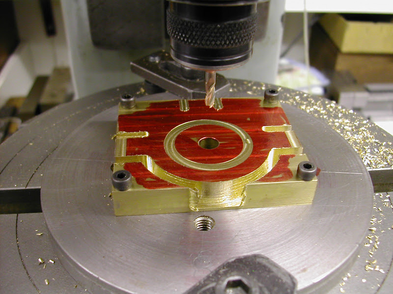
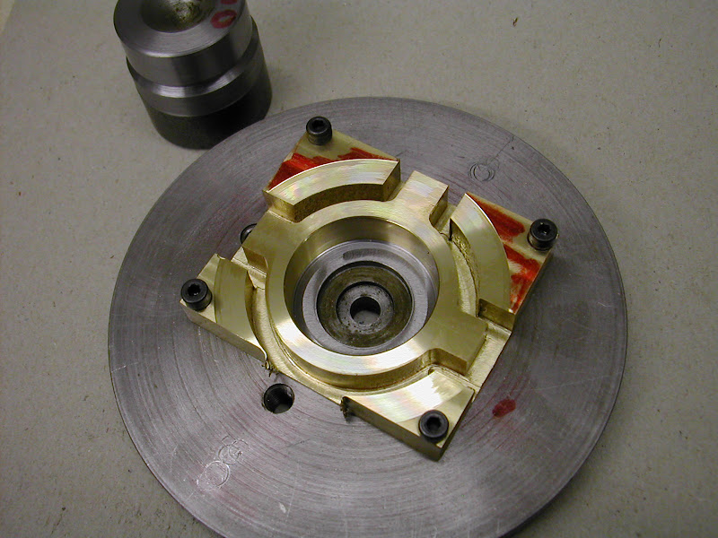
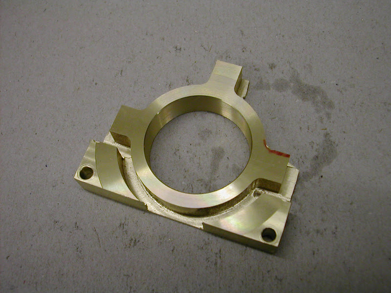
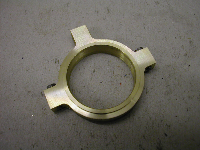
Finished milling ops ready for the lathe
DSCN3865.JPG


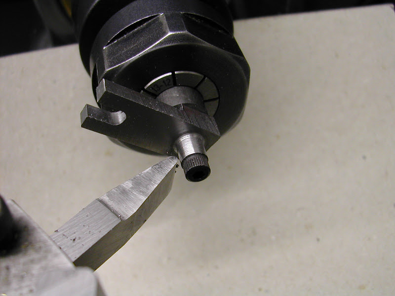
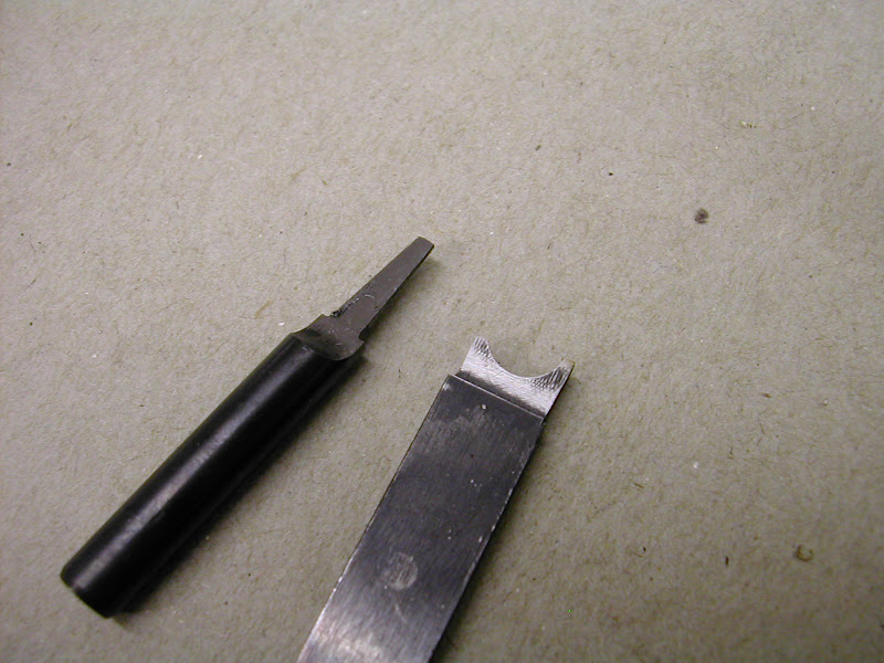
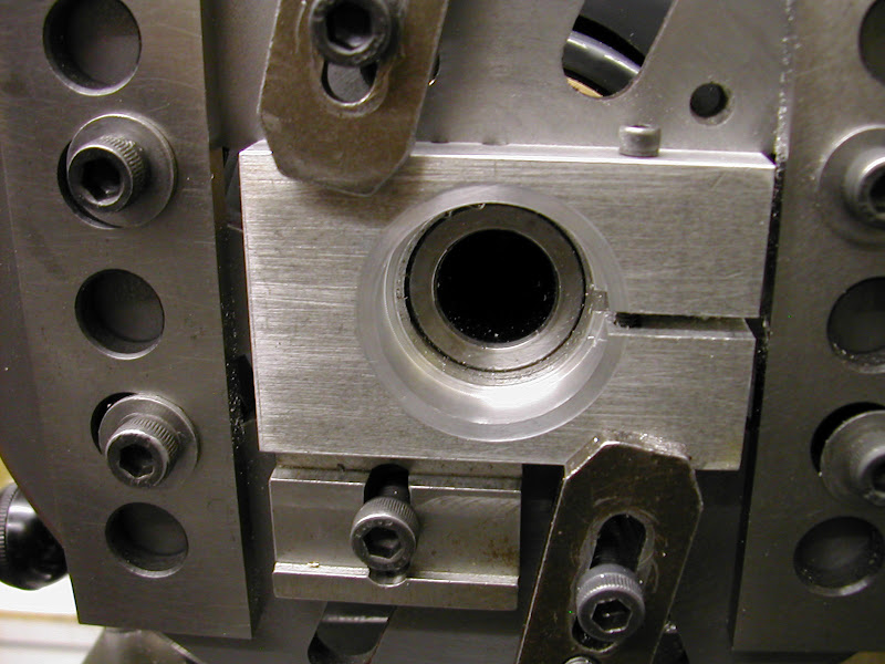
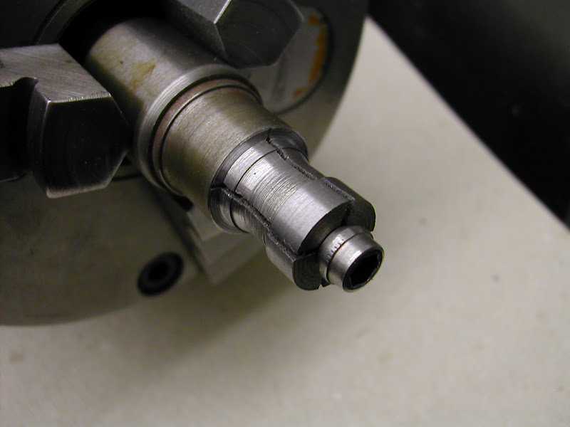
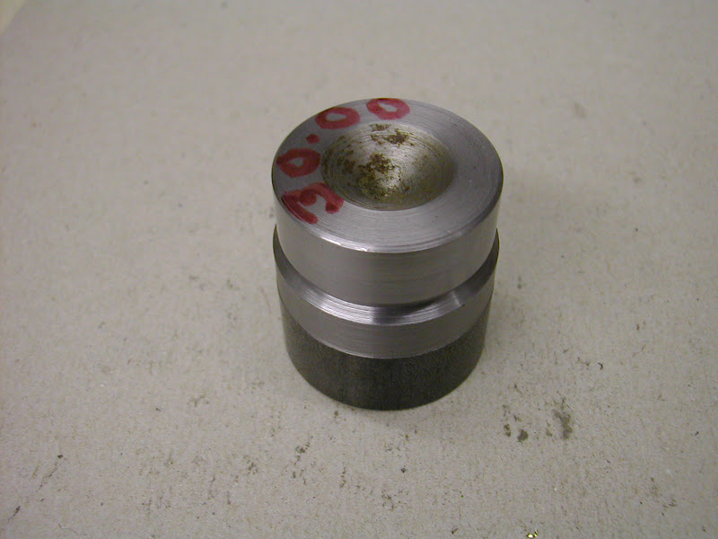
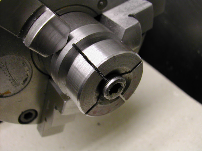
First though a plug gauge was required. Made from a scrap of FCMS it was turned .01mm larger than the eccentric sheave diameter.
DSCN3874.JPG


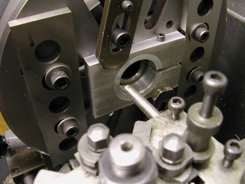
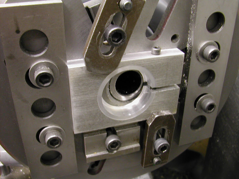
The bore was finish turned to just allow the gauge to push in easily
DSCN3875.JPG


DSCN3872.JPG


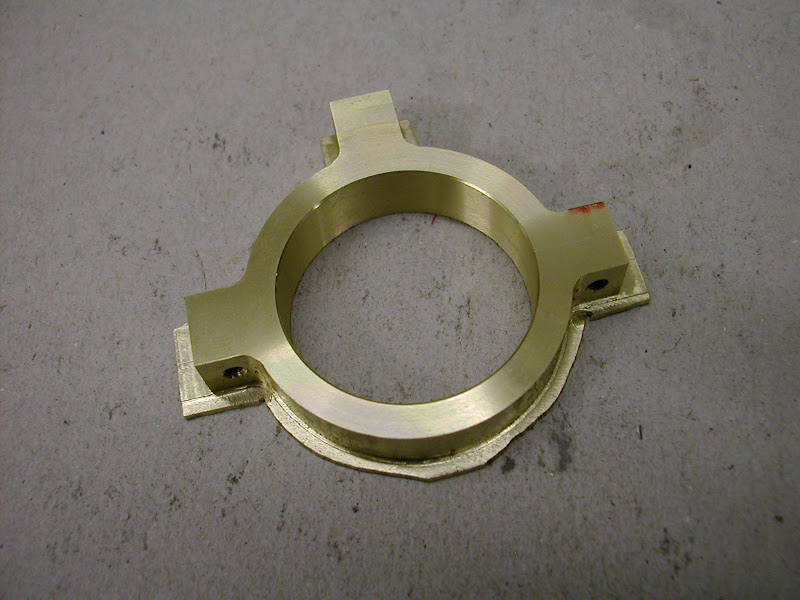
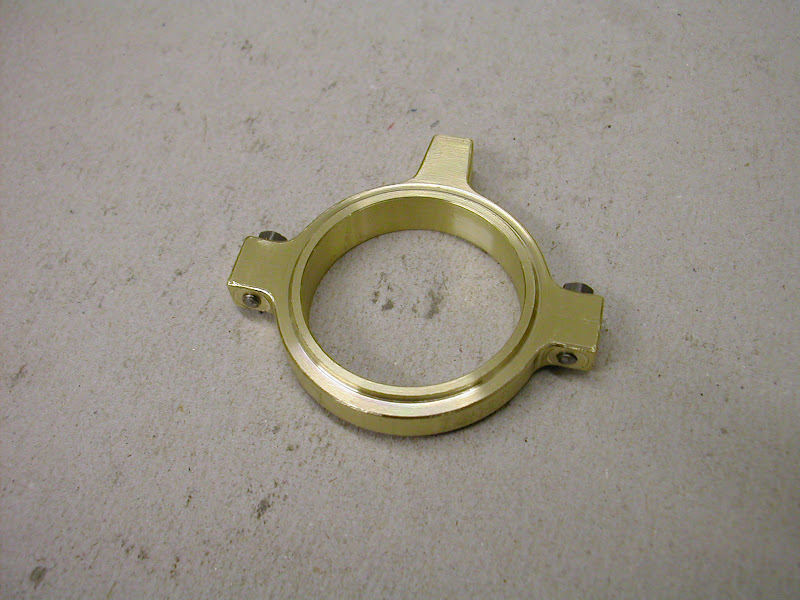
As taken off the lathe ready for the next stages.
DSCN3877.JPG


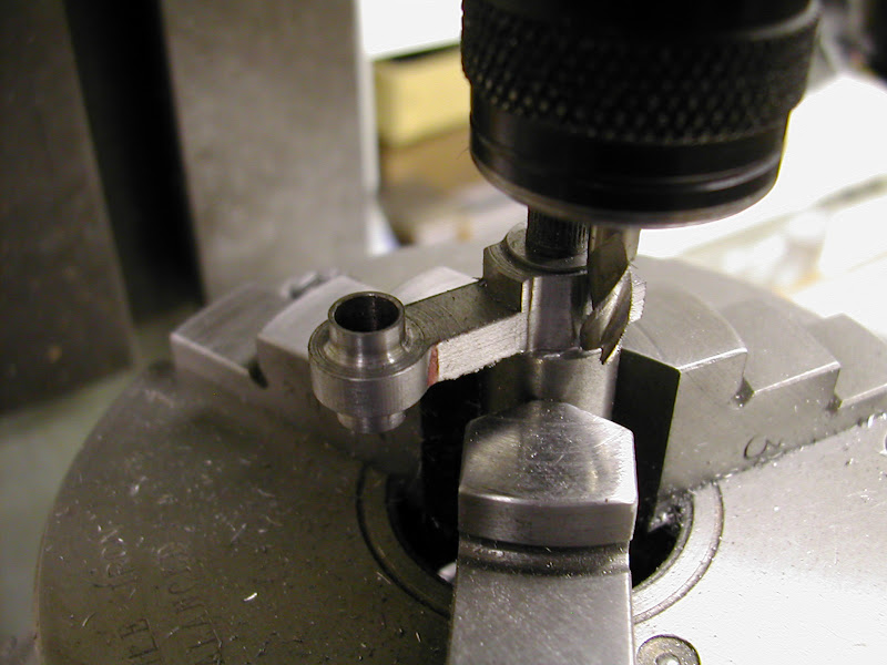
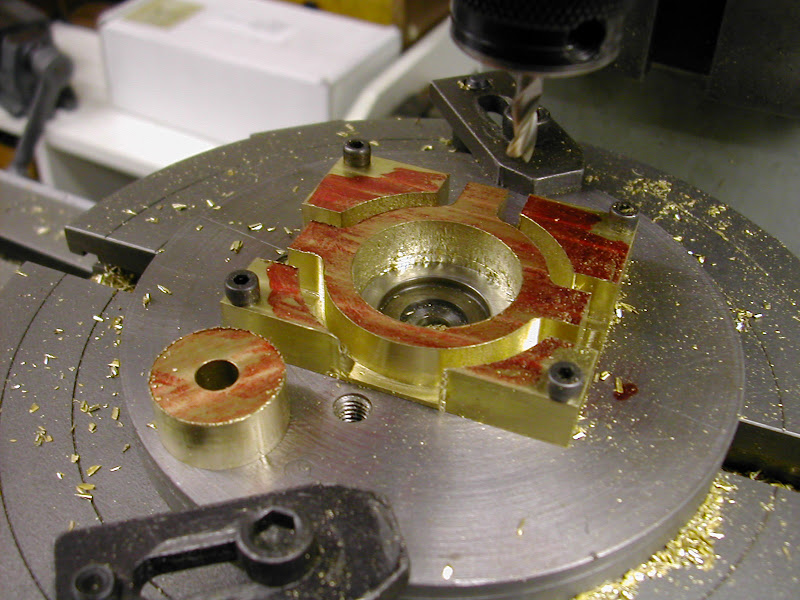
First up was to cut away the top waste and trim the lower face with a file. This was then stood in the vice and the holes for the bolts and rod drilled and tapped before the lower waste was removed
DSCN3879.JPG


DSCN3882.JPG


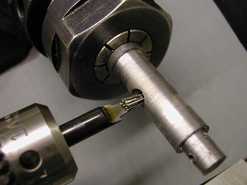
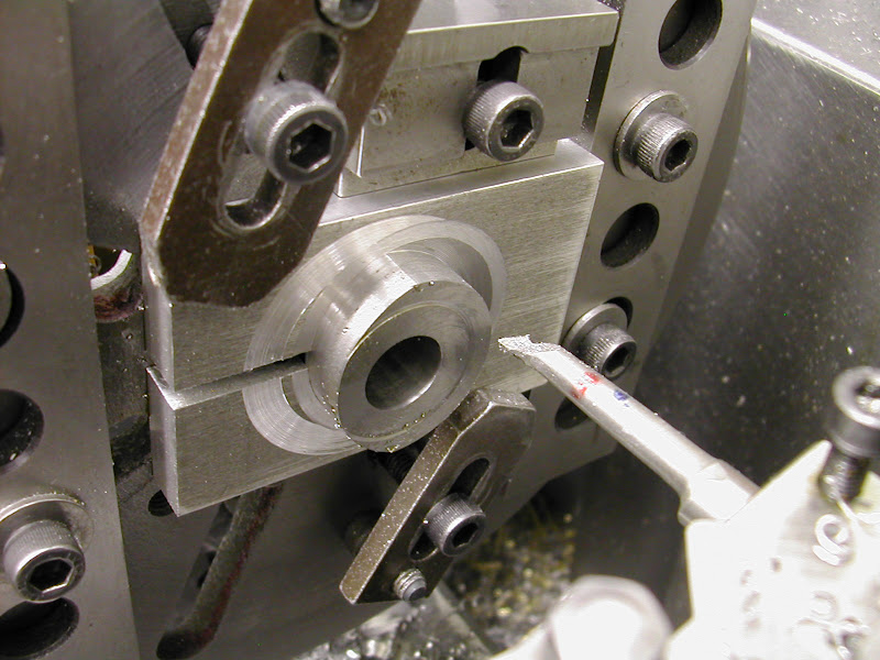
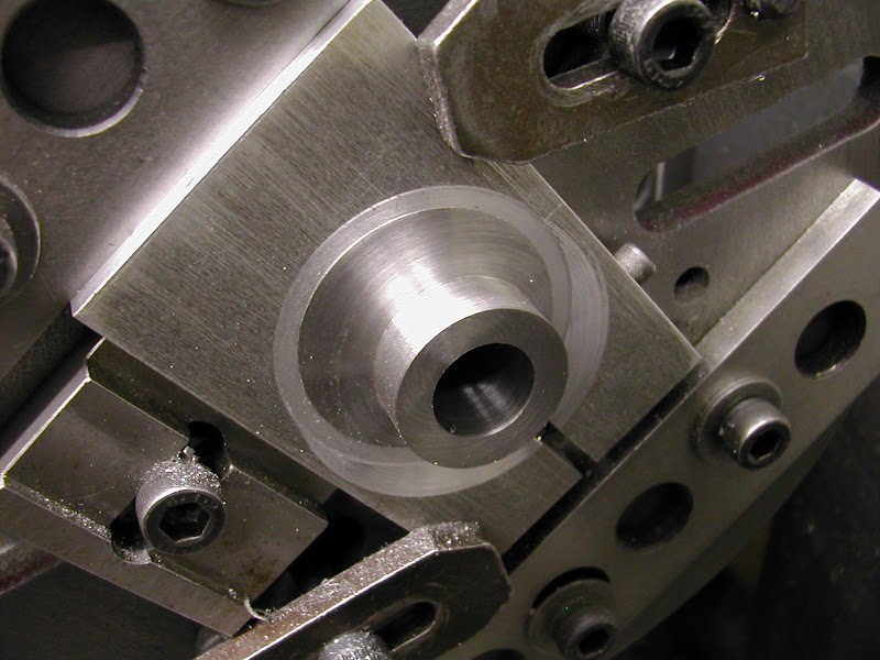
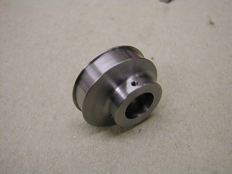
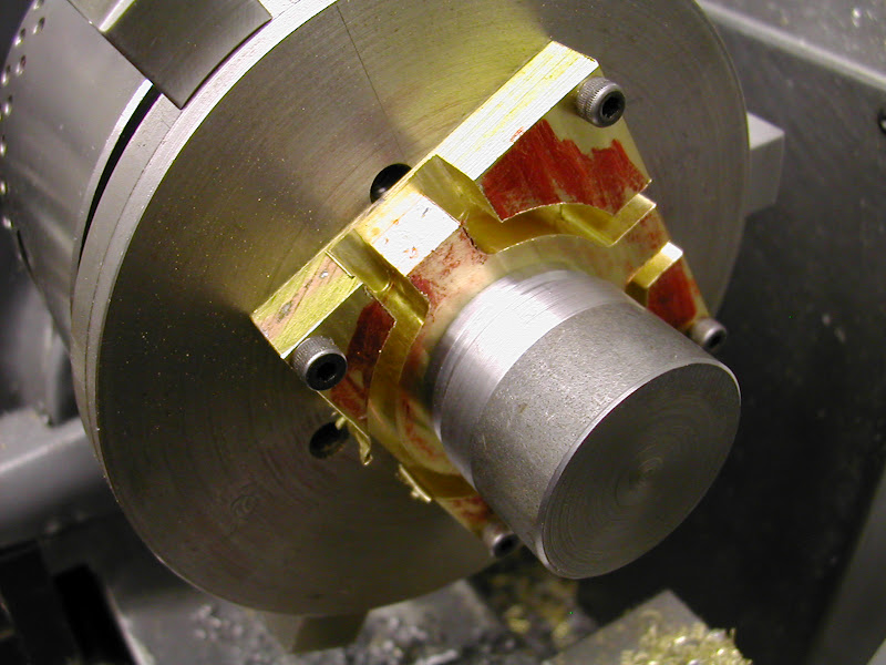
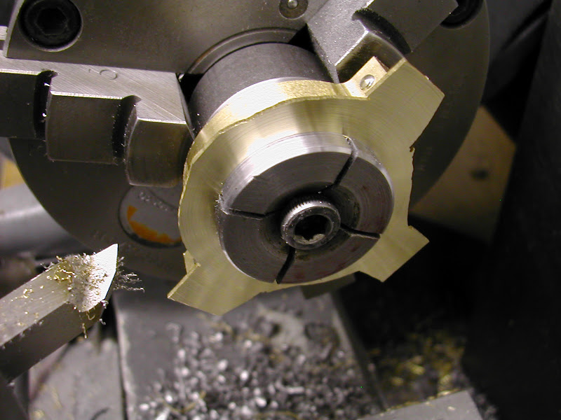
That plug gauge was converted into yet another exp. mandrel so that the surplus could be machined away
DSCN3884.JPG


DSCN3885.JPG


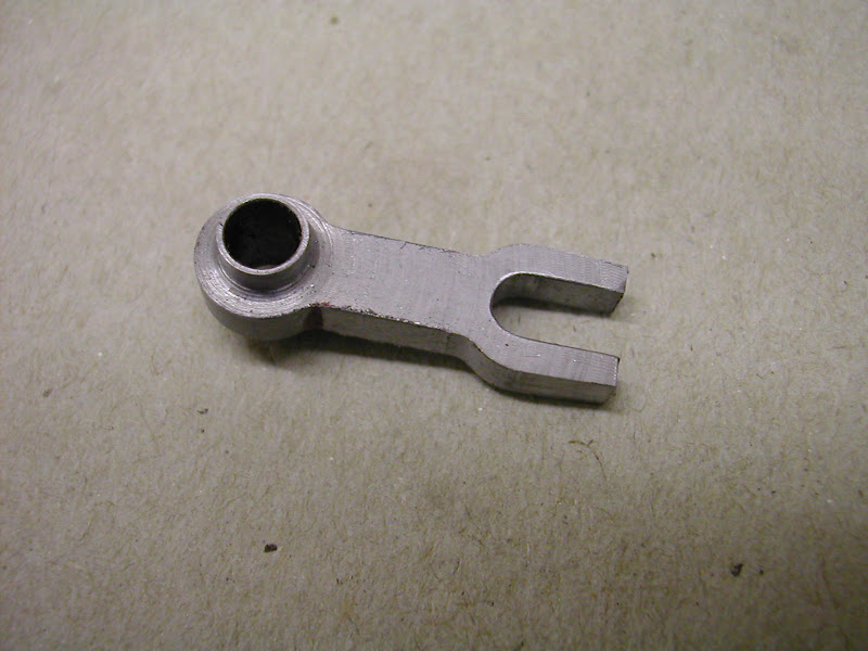
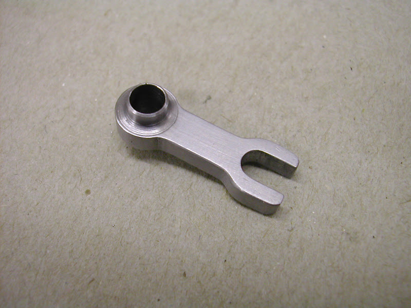
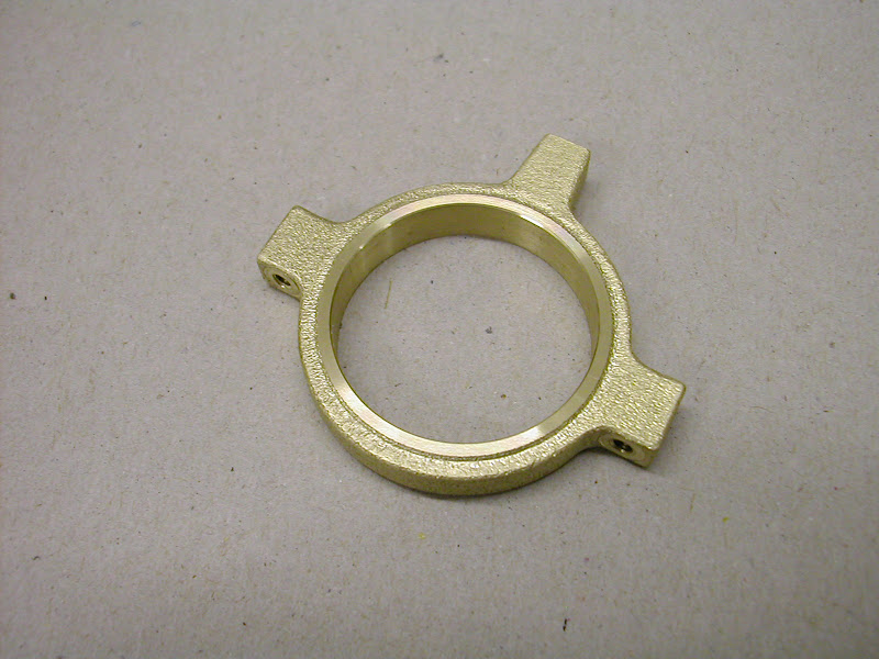
And finally an eccentric - but it's not finished yet ::)
DSCN3886.JPG


In order to simulate a cast finish first the corners are all well fettled
DSCN3890.JPG


Then comes the worry bit - after all those ops will I bugger it up ???.
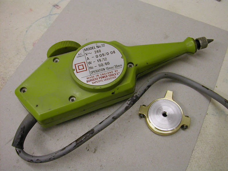
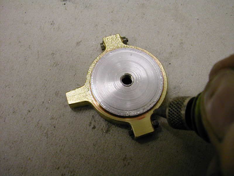
Using one of these engravers the surface is attacked - gently but with the engraver working on a 'heavy' setting at first.
DSCN3892.JPG


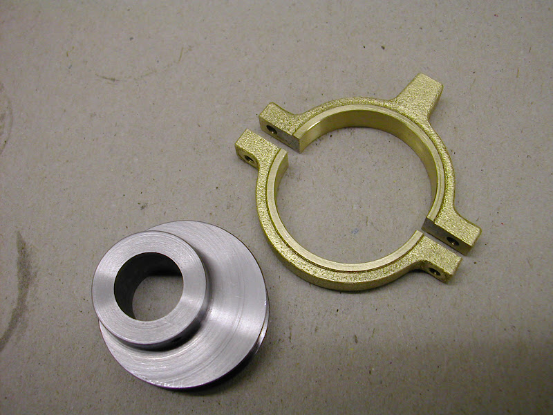
The entire part is abraded at this setting before reducing the power of the 'hit' slightly and going all over it again, doing it all for a third time at a lower setting still. This produces a degree of varying surface. It's time consuming as the surface has to be constantly gone over to ensure even coverage but it does give a reasonable rendition. This is a posed shot - it's much better to hold the part in the hand as it's being engraved. Obviously the ali part is just a protector for the bore and running faces.
DSCN3893.JPG


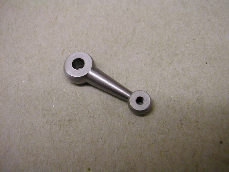
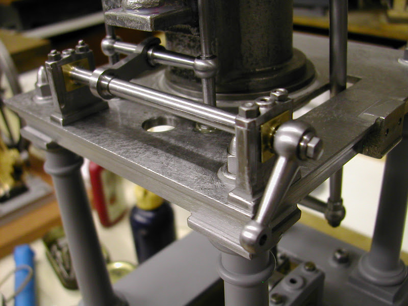
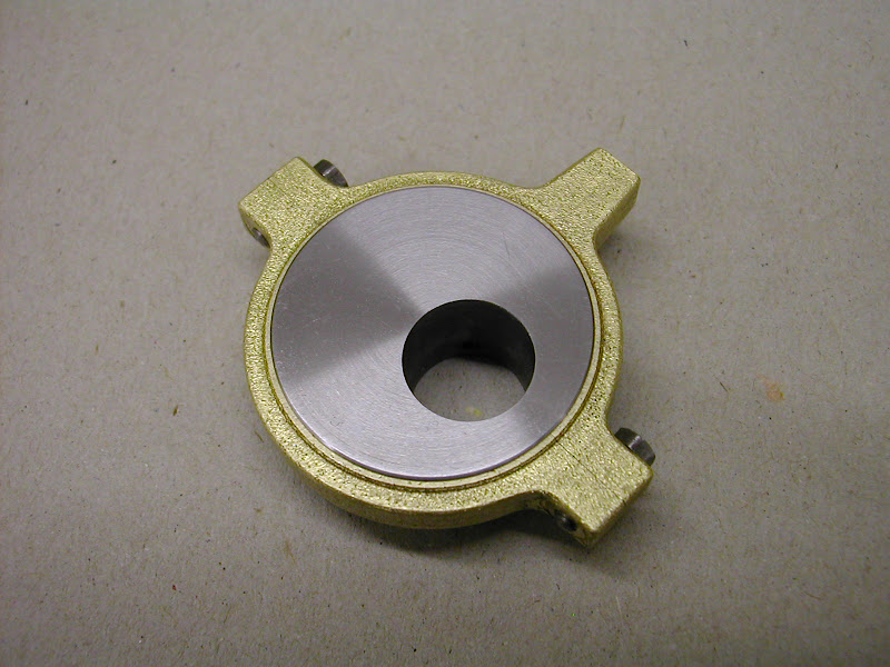
And finally, after mounting on the mandrel and facing both running faces to finished width it's there
DSCN3898.JPG


DSCN3900.JPG


DSCN3901.JPG


I don't know who it was who said you all like piccy's on here but that should keep him happy if nothing else ::)

I've had a very enjoyable time making this today - I hope the coverage of doing so will be as enjoyable for you too

One bit to make now before it can run ;D

See you later
Regards - Ramon


Wow - that really looks like it was cast!
This whole thing is fantastic. And I, for one, love the pictures.
 
I don't know who it was who said you all like piccy's on here but that should keep him happy if nothing else ..."


I know who that was...it was this person called....EVERYBODY!

;D

Dave
 
I've used pipe plugs as expander bolts for expanding mandrels before...they work well because their tapered...

Dave

 
Morning Dave, the old glims are a bit bleary after staring at this screen for so long last night :eek:

Anything tapered is ideal so can see a pipe plug working fine. I've got a few capheads pre turned with a 60 degree taper to match that of a centre drill from 2mm, through 8,4,2BA and 6mm. It's amazing how much pressure can be exerted with so little torque on the screw.

Weathers good today so it's more in the garden first but maybe this afternoon.........

Glad you liked the pics Jeremy ;)

Regards - Ramon
 
Hi Ramon
Wow what a great Post :bow:
love it !!
Pete
 
It's always good to see lots of pictures to help visualize the process being used and steps taken. I for one have never seen a post with too many pics. ;D

Ray
 
Hi guys its 15.47 here - just thought you might like to know it's now running ;D ;D ;D ;D ;D ;D albeit on a temporary eccentric rod (to ascertain the length)

More later - Ramon
 
Wow, what an inspiration! Love it. :bow:

Simon
 

Latest posts

Back
Top