A Table Engine Tale

Home Model Engine Machinist Forum

Help Support Home Model Engine Machinist Forum:

This site may earn a commission from merchant affiliate links, including eBay, Amazon, and others.
"I don't think we need to go shopping this week dear" - No?, really? well... faster than a speeding bullet I was in there, lathe on and ready to go :big: :big:

Had a good day playing and finished off the globe valve and inlet - heres some pics of the sequence........

The top and the threaded boss to be. The thin rod is 1/16 brazing rod.
DSCN4221.JPG


First bend. This is the second attempt - on the first the thin bar got too hot and distorted and then I went and bent it the wrong way :Doh:
DSCN4228.JPG


Much better and looking promising
DSCN4229.JPG


The small circular wrench was pressed into service again but proved insufficient leverage for the 6BA (used) tap in the brass
DSCN4233.JPG


A short spigot was turned up to keep the parts in line. Though not close to the area to be soldered it was blacked up by heating and dipping in oil several times to prevent possible accidental soldering.
DSCN4235.JPG


DSCN4236.JPG


Fluxed up ready for soldering
DSCN4241.JPG


Parted off from the parent rod it was still held on the steel spigot and this used for cleaning up the back face
DSCN4244.JPG


Ready for final cleaning up and having the casting effect applied - actual size is 14.4mm major dia with 6BA thread
DSCN4245.JPG


Ready for assembly. The spindle is turned from an electric arc stainless welding rod (Flux removed first of course ;)). This turned reasonably well without distorting unlike the material used for the throttle rod
DSCN4248.JPG


Trial assembly to the pipework
DSCN4252.JPG


DSCN4254.JPG


And a trial fit to the engine. Try as I might and despite two separate goes I could not get one pic of the valve to come out in focus - too much background to deal with I guess. I'm not sure about the hand wheel - it seems a mite over scale but it may look better once the pipes are lagged. This is as far as the inlet side of things can go now until the engine is mounted on it's proper base.
DSCN4261.JPG


Well, to coin a phrase 'it's now on the last knockings' - just those governor/throttle linkage parts to do.

Back a bit later then

Regards for now - Ramon
 
Ramon,
Your whole engine build is some of the best work of this type I've seen on any forum.

Pete
 
Amazing work and attention to detail throughout the whole build!!! ;D

This is a great journey to follow!
Lots has been learnt along the way!!!

Thanks Ramon!!! :bow:

Andrew
 
I've pondered how to make that kind of valve in miniature....brilliant!

Dave

 
Your attention to detail is incredible. You are sure an inspiration to me and I believe many others on this board. I am in awe of your work!

Harold
 
Excellent work as usual Ramon.
gbritnell
 
Very nice Ramon, good to see I'm not the only one with a couple of rusty toolmakers clamps for soldering.

J
 
Great work - I just love the tips and tricks that enter my head from threads like this one - great stuff.

Ken
 
Ramon:

The valve looks great. The hand wheel looks OK, but it might not look so massive if it had spokes instead of being solid.

Just something to think about,
Don
 
:bow: :bow: :bow: That valve looks right at home on the steam ship I volunteer one !! WONDERFUL !!!
 
Hi guys, once again my thanks to all for your kind and appreciative comments.

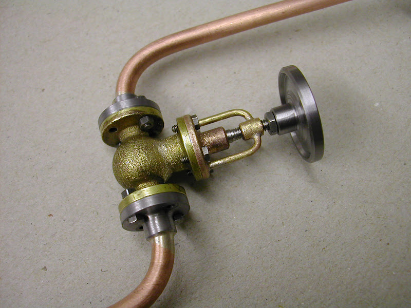
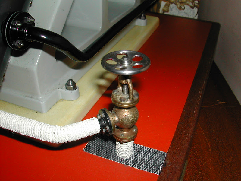
Don, The handwheel was finished late in the evening but that was my thinking too - just a bit late in the day to get it done. This pic is of another valve I made for a double diagonal engine - which I think, definitely looks more in keeping so I shall make another and spoke it.
DSCN4300.JPG

Now, having made a 'mistake' several years ago having put 6 bolts in a flange when I was duly informed it should only be 4 or eight - what would be correct - three, four or more spokes?


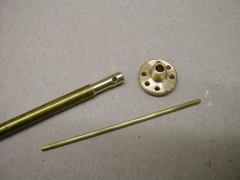
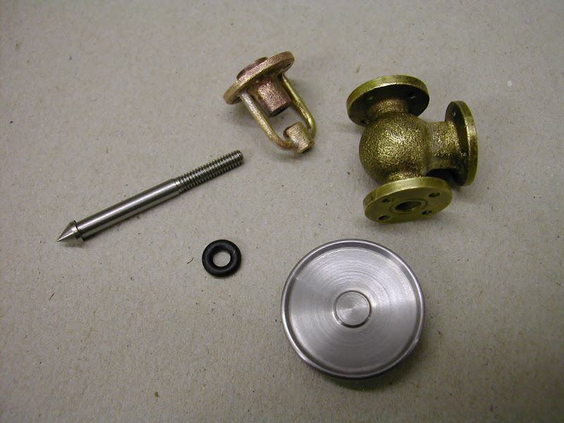
I have little to report save for one small part but I was pleased with the result.

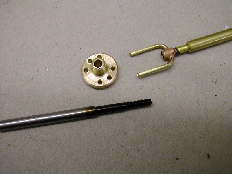
The throttle arm support bearing on the original AM design is just a small slab of 1/8 bar stood vertically with the bearing hole drilled through. It was felt that this would have been a small casting on the fullsize so this is what transpired......

After considering a composite - three parts, silver soldering, JB Weld etc it was decided to mill and turn it from solid
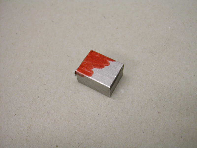
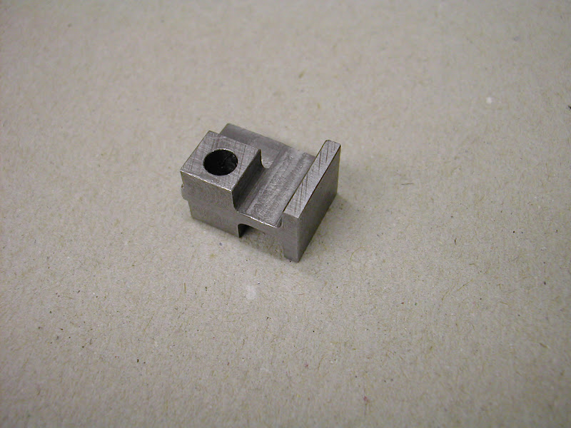
Began with a small block 15 x 12 x 10mm
DSCN4267.JPG


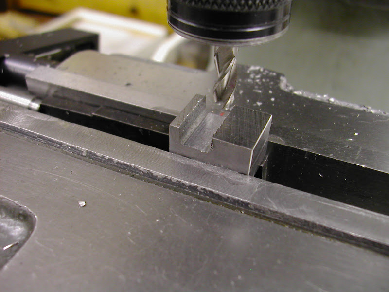
After squaring up it was set at a 2 degree angle to mill the feet with a 'draft angle' . The 5mm FC3 cutter has had the corners 'radiused' by hand on the offhand grinder
DSCN4271.JPG


DSCN4274.JPG


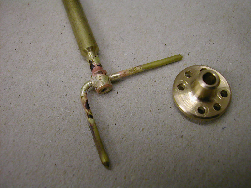
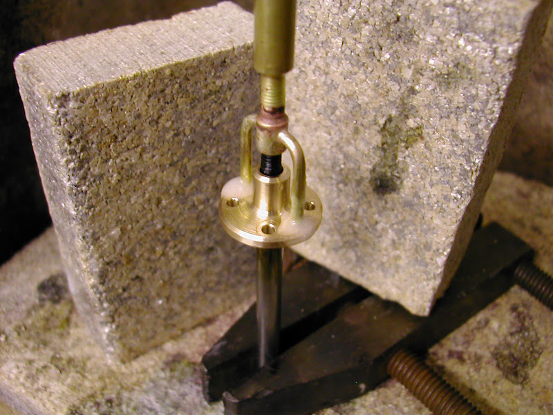
The cross hole was drilled after carefully measuring the distance from the entablature to the centreline of the throttle rod but less carefully adding the two dimensions together and missing a whole mil off :Doh:
DSCN4275.JPG


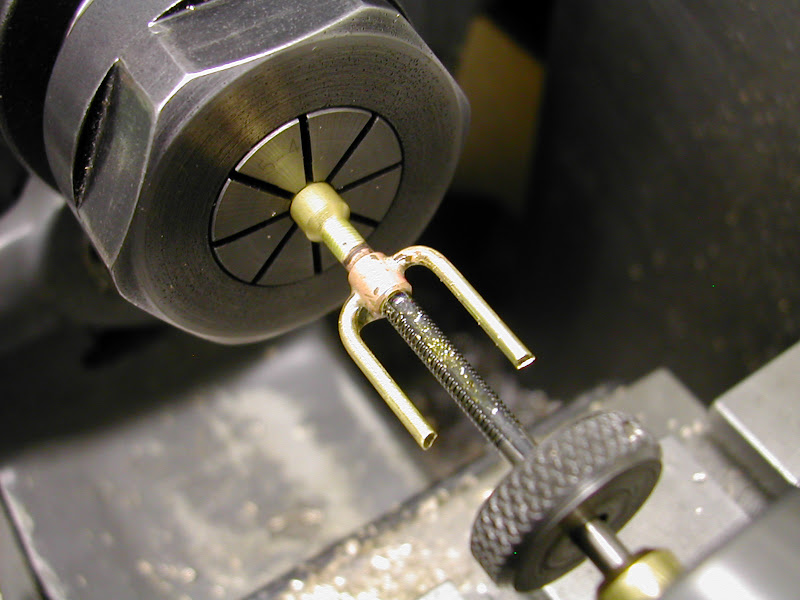
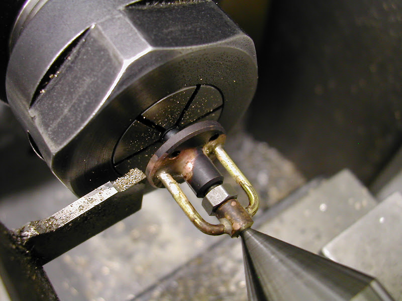
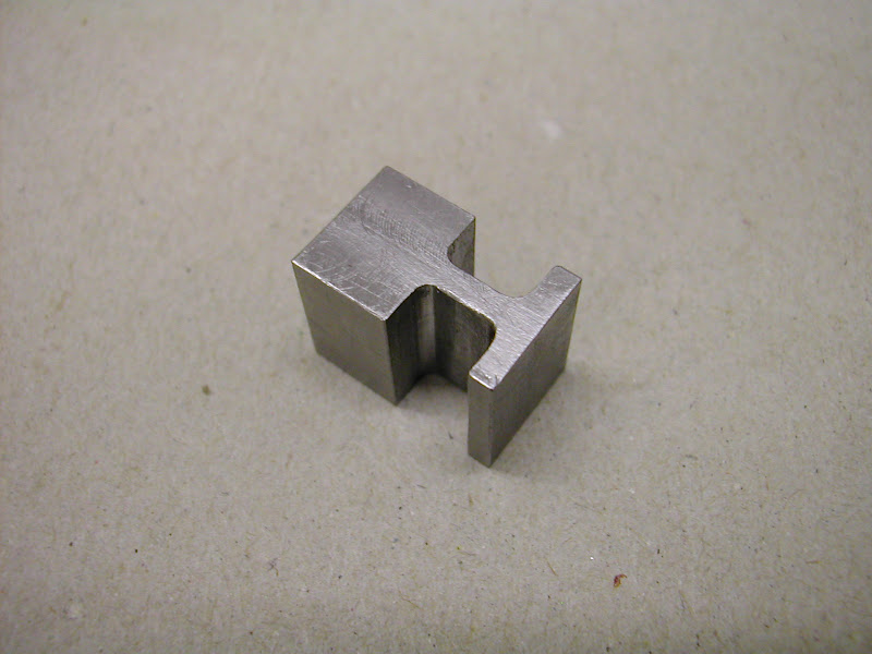
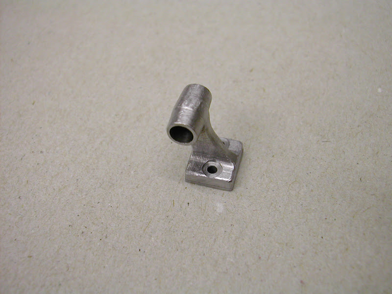
It was held on a small 4.0mm expanding mandrel and the housing each side turned, again at a 2 degree draft angle
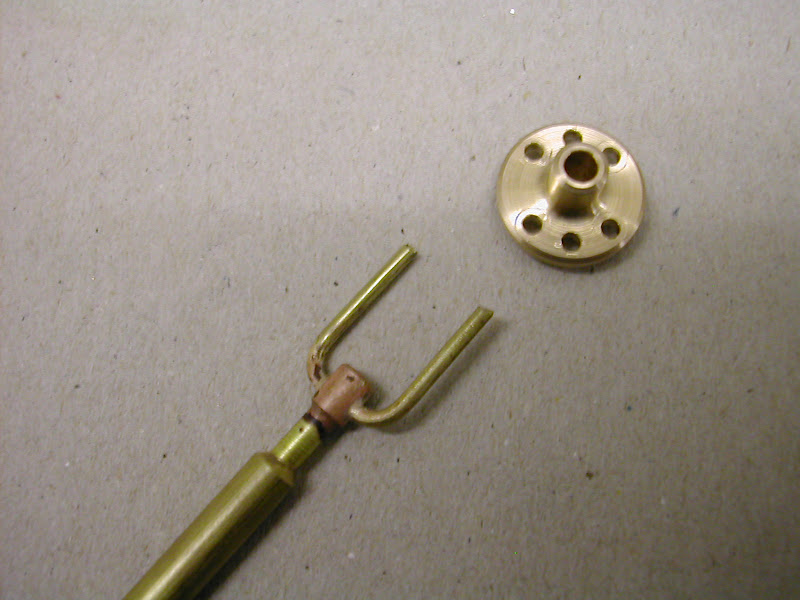
then the surplus material was cut off on the bandsaw and the profile shaped by linishing and finally filing.
DSCN4279.JPG


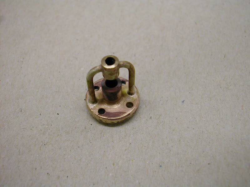
A 1.0mm shim was milled from the same material and bonded on with JB Weld then filed to flare in.
DSCN4283.JPG


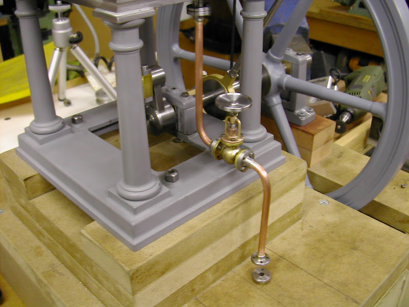
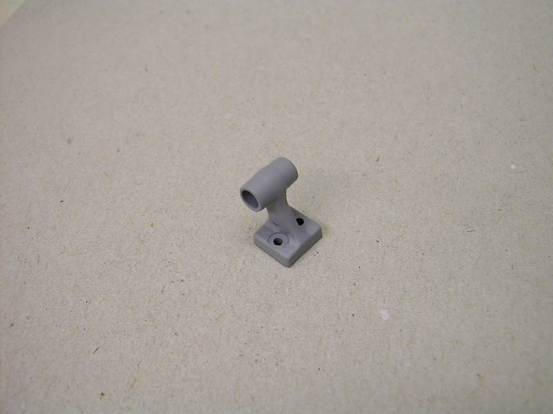
And a coat of primer brought it to life
DSCN4288.JPG


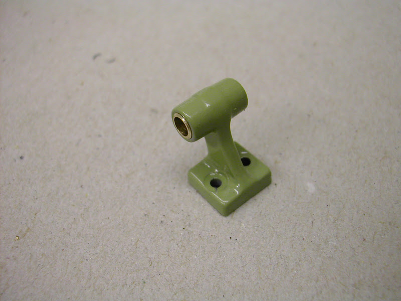
Finally fitted with a bush there's a hint of shades to come. This looks much 'greener' than it actually is. It's 'Vauxhall Reed Green' and which is quite a pale shade. (Must be down to the lighting) Wife likes it though Thm:
DSCN4289.JPG


It's going to take some very careful measuring - very careful given the last time :-[ - for drilling the bolt holes to position it correctly as theres very little room for opening the bolt holes to allow a degree of lateral movement.

It's a simple part and certainly easy to machine but one which has given a fair degree of satisfaction.

As usual hope thats of interest for someone.


Regards - Ramon
 
Ramon said:
As usual hope thats of interest for someone.

Hell yes ! - that's engineering artistry !

From a "block with a hole in it" - to that !

Your attention to detail continues to fascinate me and encourages me to do better.

Ken
 
I looked at this thread when it was first posted and to be frank the early references to "JB weld" put me off, thinking that it was going to be spread around liberally like modeling clay. How wrong can first impressions be? I now know what I've been missing, I'm sure we are all learning something through this thread.

Note to self - get some JB Weld...............

Pete
 
That blocks almost a model in itself!
such attention to detail. I wouldn't have even thought of rounding the corners of a cutter or maching in the draft angles.
I guess like a lot of people here, can't wait to see the finished engine.

was the expanding mandrel shop made? love to see a photo

peter
 
There hasn't been a post yet where I didn't learn something. I'm really looking forward to seeing the completed model.

Ray
 
Well I do want to see the completed model, But I'll also not be all that happy to see the end of this build, I've picked up a huge amount and have thoroughly enjoyed it.

Pete
 
Real nice job ... looking for MORE! :big:


Pat H.
 
Like Pete, I am enjoying the journey. I am not sure that I am actually learning things that I could do but I am certainly learning what can be done. For me it is a regular dose of humility and wonderment.

Thanks a million

Jim
 

Latest posts

Back
Top