A Table Engine Tale

Home Model Engine Machinist Forum

Help Support Home Model Engine Machinist Forum:

This site may earn a commission from merchant affiliate links, including eBay, Amazon, and others.
Well done Indeed! I think one of the most satisfying things I've ever done in my workshop was make my first gears.
 
I wonder if making a FDH from aluminum would give you more feel, since it has less mass? You've given me some nice ideas for improving my bare-bones tailstock die holder!

Wow, that governor is beautiful! :big:
 
Hi guys,thanks for the response

Dan - glad that's of use and thanks for the pointer too- isn't it great when you know what you are doing ;) - and thanks to John too for downloading the pages. (I confess it still took me some time to find exactly where but got there in the end ::))

'GWR' For many years the buzz I get from making something that fits something else well is one thing but for some reason that is always superceeded by making a cutter which then performs how you hoped it would and seeing the result. For me that never fails to bring on a big grin and as you say - immensely satisfying.

Thanks again - Ramon

Your post has just come up as I was previewing this Simon - Yes I'm sure it would, infact I was thinking the very same thing this morning as I was using the steel one. I need to do something for small taps too - what I have is simple but needs 'growing' a little - perhaps a bit later.
 
Hi Ramon,

Stunning, just stunning!

I am lost for more words!

Er...I see the Y axis movement for cutting the first gear but don't quite see the X axis movement for the second. Do you mean that you climb cut it? What was the difference in speed and finish?

Andy
 
Andy as its a 2:1 bevel the angles of the bevel are not the same, the small wheel will be say 60deg and the large wheel 30deg.

The dividing head is set at 30deg to the X axis which puts it at 60deg to the Y axis so by feeding it one way you get a 30deg bevel and the other way gives a 60deg bevel.

J
 
Tel, good to see you are still keeping an eye on things - that's a nice set you have there and an impressive looking bracket - cast or fabricated?

Fabricated matey, turn a ring, cut it in arf, and go from there!
 
Love the filing rest Ramon! Great job on the parts!

It's coming along great!

Dave

 
Hi guy's It's a bit late to post the latest progress tonight but I would just like to say thanks to all those who have responded since I began on here - you have made me feel very welcome :).

The comments recieved so far as well as all those silent ones who obviously just enjoy looking make contributing an enjoyable extension of the time spent in the workshop. On that note then I'd like to wish you all a very Happy and most productive New Year for 2012.

The engine is now at the 'home run stage' - exhaust done and inlet well underway so will see you in the new year with last years news (Tomorrow that is :D )

All the Very Best

Ramon
 
Happy New Year everyone -

Tel, I can see you are a man of few words but much wisdom ;) 'Cheers mate'

Andy - Jason has summed it up exactly though in this case the gears were 1.5 to 1 but the principle is the same

Dave that little filing rest is a boon at times - strange thing is those hardened rollers simply will not roll at all as a file touches them but will roll instantly if theres some emery or wet and dry under the file ???

After some prep work on the base for the new extension to the workshop and a couple of hours or so of leaf collecting duties I managed to get into the workshop this afternoon very keen to get on - too keen as you will see ::)

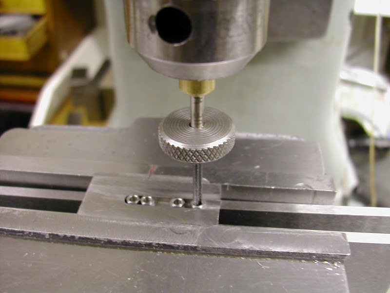
First though as mentioned previously I have long felt the need to improve the 'tapping facilities' and particularly so for the very small taps. For years, and more by luck than judgement, I have got away with using a very small flat bar type wrench that locates a small flat ground on the side of the tap toward the bottom of the shank. After drilling on the mill this is then held lightly in the drill chuck and the hole tapped by hand using the drill chuck as a (loose) guide to keep the tap vertical.

With the exhaust flanges done it was time to make some nuts (8BA thread 9BA outer) and another perennial problem. In the past nuts were always tackled by drilling a deepish hole into some hex bar, tapping as deep as possible then parting off. Parting off is always affected by the helix of the thread and there then follows an awkward second op to debur the back of the nut.

It was time to improve matters on both counts ... and this worked really well ;D

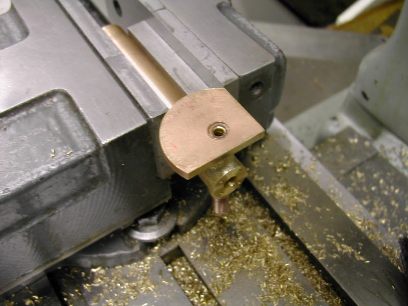
A brass bush about 25mm long was drilled to suit the tap shank - in this case #35 2.8mm (why is it taps never seem to have a consistent standard in shank sizes) and gripped firmly in the chuck. The tap shank was just a nice slide fit in this bush. The small piece of steel had a groove milled in to just take the hex blanks which had been pre-drilled, parted off and chamferred on each face. The tap wrench is just a slice of MS 16mm diameter about 5mm thick and gives more than sufficient torque for the task as well as giving far greater sensitivity. I found I could do four nuts at a time letting each one ride up the tap then sliding the next one along. In short a real big improvement from the previous method. Another bonus with this 'circular wrench' is that tapping is carried out using one hand. Also, in the smaller sizes theres probably no need for a flat on the tap the grub screw grip being more than adequate - any slippage possibly even providing a 'safety' factor. I can now see a series of such wrenches on the cards

DSCN4156.JPG


The exhaust has been kept simple - the engine will probably only run once a year so it can be extended then if required
DSCN4195.JPG


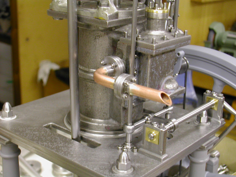
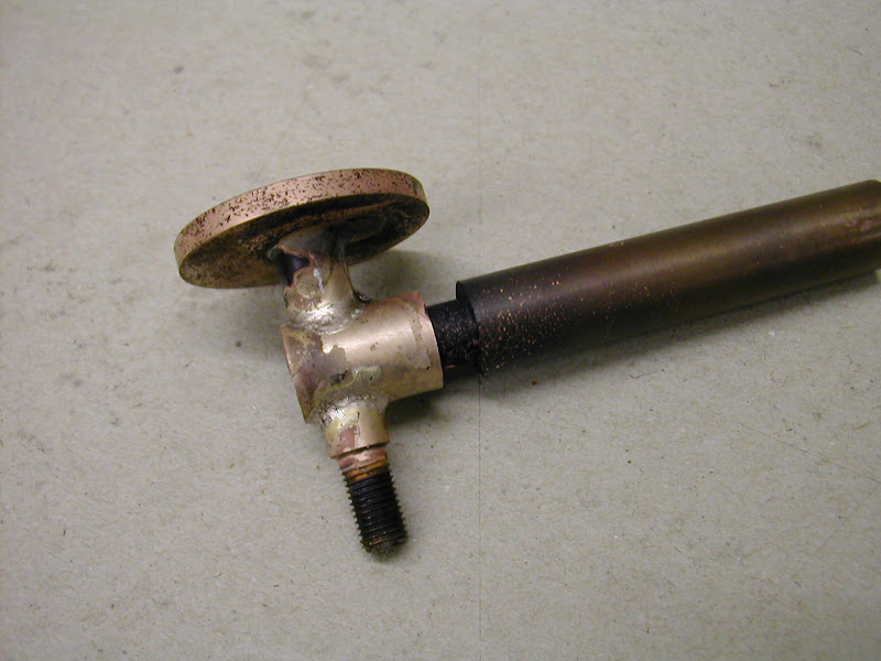
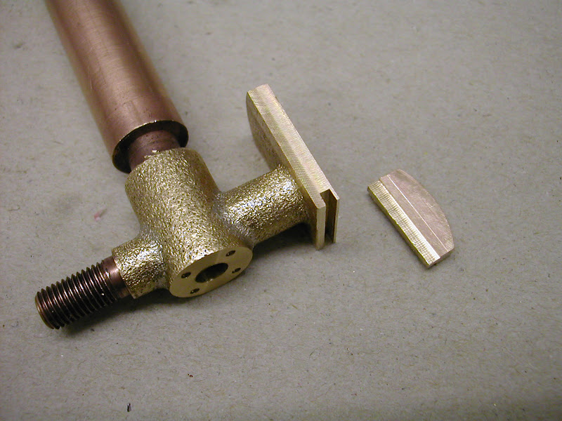
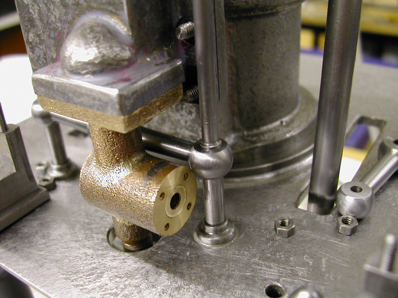
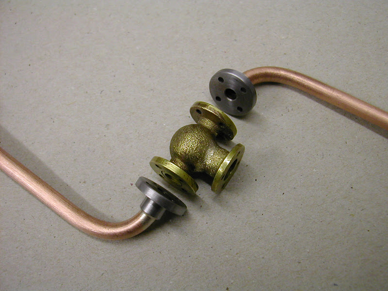
With that finished it was time to get on with the inlet. The original engine as designed by Anthony Mount had the inlet steam coming up through the centre of one of the columns through a cavity in the table top and up into the steam chest, the exhaust exiting by a similar route down another column. Whether this was true to prototype I have no idea but it does seem a rather good way to condense the steam before it gets to the steam chest ???
It was decided to fit a more conventional one that would hopefully look in keeping.

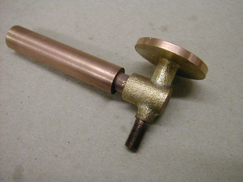
Heres some pics of the progress...

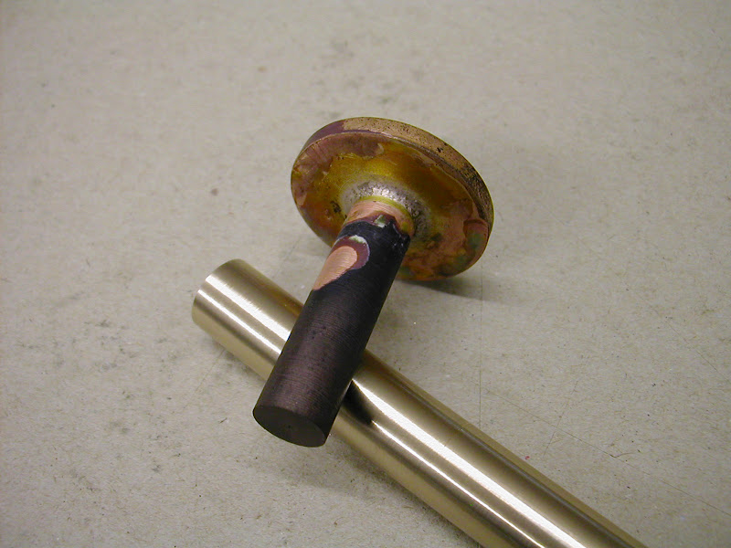
The upright was soldered up to save material
DSCN4159.JPG


DSCN4160.JPG


DSCN4163.JPG


DSCN4165.JPG


DSCN4171.JPG


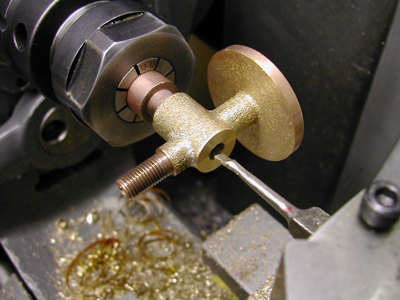
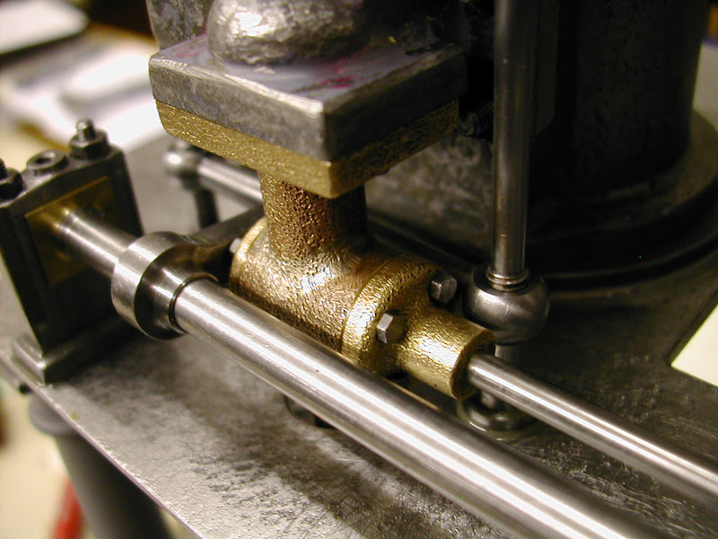
The hole for the throttle bar was bored to ensure a good fit and concentricity. I've had the crude looking boring bar for the best part of forty years - its done countless bores over that period but gets thinner each time - a real favourite tool ;)
DSCN4172.JPG


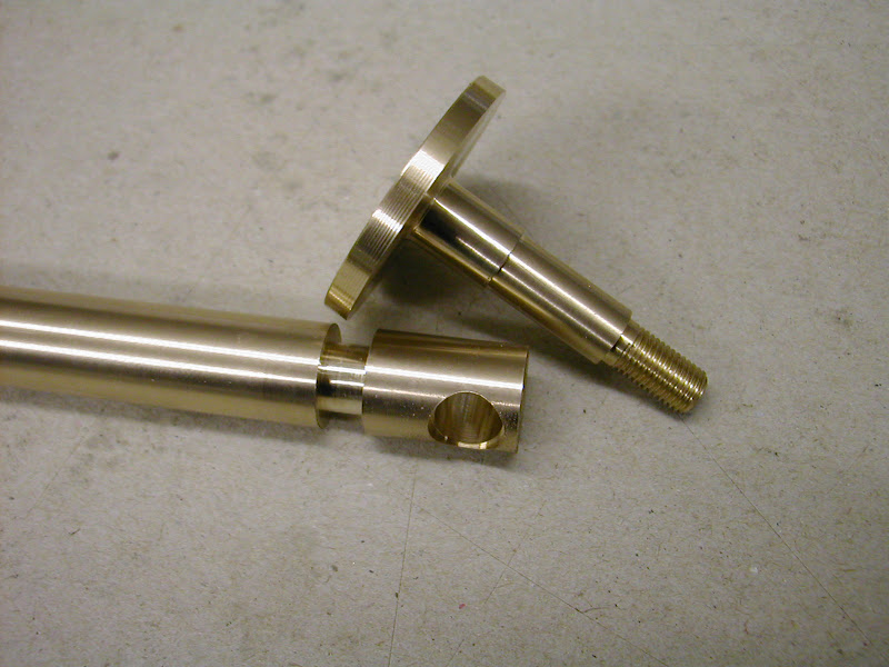
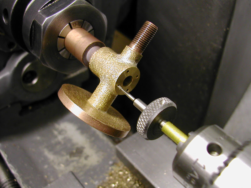
Tapping again - this time 12BA using a small piece of 1/8 brass tube - much better than relying on loosely nipped chuck jaws
DSCN4175.JPG


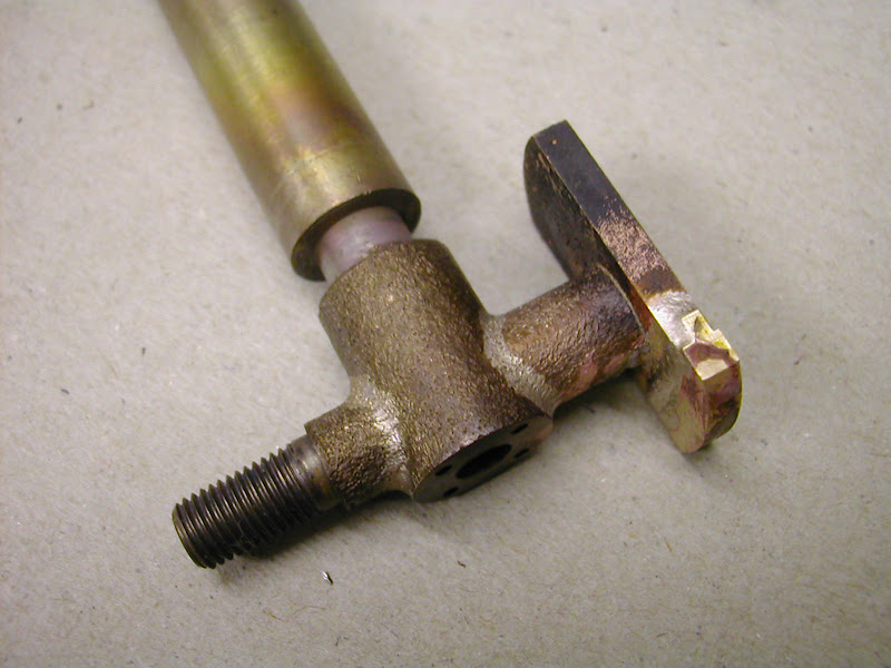
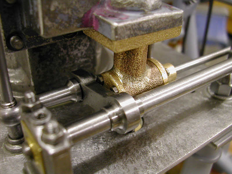
'Less haste more speed' however...... These two sides are 90degrees out of phase :eek: :Doh:
DSCN4176.JPG


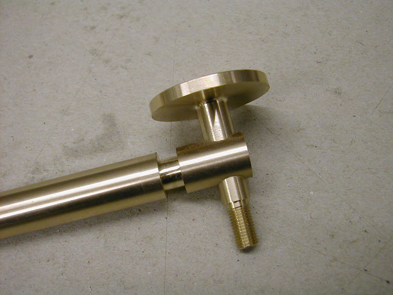
Fortunately there was enough left to come off the remaining sides to elicit a repair
DSCN4179.JPG


DSCN4184.JPG


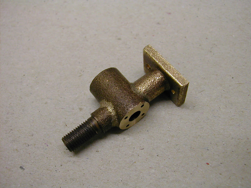
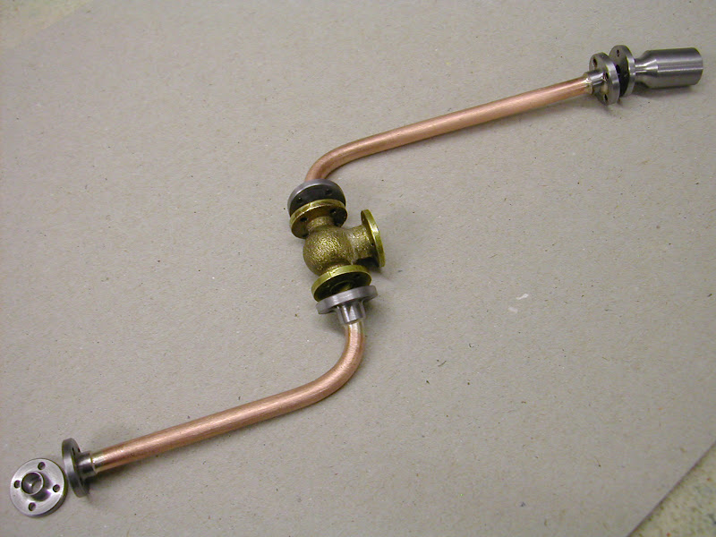
Cleaned up and parted off it's ready for the next stage so more on that later
DSCN4189.JPG


As usual hope theres something there for someone to make use of.


Regards for now - Ramon


That's odd Ramon...my rollers turn just fine!
Odd
try using less oil on the rollers.......?

Your work is awesome as usual!

Dave
 
Thank you Ramon, the useful information just keeps pouring in - now all I have to do is remember it. Your method of tapping nuts is just superb; I have never seen anything like it before but it is one of those things that make me say "that's obvious" - high praise. And the use of brass tube as a bearing for tapping is equally ingenious.

I have now arrived at the point, having read the thread from the beginning, that I will have to go back and do it all again with a pen in my hand. I think that is one of the important things I have learned from your thread.

That said, I hope you have a happy and productive 2012 and I look forward to more inspiring posts to keep me sane.

Jim
 
More and more stunning! :bow:

Jason, a belated thank you for the explanation. :bow: I see it all now... :big:

Andy
 
Holy Cow!!!!!!!!!! ;D

I looked in at the beginning and must have missed a few pages!!
Just finished catching up and everything you have done just blows me away!! :bow:

All the pictures and explanations and set ups are great!!!

Do you have a thread here for the machines you are using??
Looks like your mill is CNC?
Would love to have a look around your shop! Pictures of course!! :big:

Andrew
 
Ramon, can I ask how you got the surface finish to look like it was cast? Sandblast ?
Great work here, very nice.

John
 
Still enjoying the ride and soaking up all the great tips. Your mistakes look better than my successes. ;D

Ray
 
Hi guy's, just come in to post some details for 'Firebird' on another thread and caught up with this.

Jason has beat me to it John but yes it's no more than using a Burgess engraver. Cor! those things make a racket.
The idea of using this to create this effect came from a conversation with that late, great, model maker Ron Jervis at a model exhibition. When I comented on how he had produced such a lovely casting effect he revealed all.

Andrew, I have no CNC - I wish, well perhaps not, I don't think I could give the time to learning how to do it all - again (I came to CNC in my last four years of working) I have just a smalll Linley mill and a Super Seven lathe plus a drill press and 5"and 8" off hand grinders. Theres a little Kennedy power hacksaw and a small burgess bandsaw. The Kenedy is rarely used but the burgess I couldn't live without.

Most of the accessories have been made or gradually purchased over the years but nothing special

It all lives in a 14 x 14 ft wood workshop. It's warm and dry and I spend most of my time in there that I can ;) and where I'm now off to :D. Once the last parts of the Waller are completed I'll have a tidy up and post some pics of it.

The steam inlet didn't quite work out as sketched out as it fouled the valve gear but that has been solved and the part is still being worked on. I have been able to couple it up to air properly though and am pleased to say it will tick over steadily at less than 50 RPM without hunting. That big flywheel helping there I guess.

Thanks as usual for all your kind comments and the PMs, I'll be back later with a few more pics of these final stages

Regards - Ramon


Thanks for the info!!
Looking forward to the pics!!

This is the picture that prompted the question.
Now i understand the careful setting up of a rotary table can get these results!
It just looked too perfect! ;D

Andrew

DSCN3860.JPG
 
Hi Guys, just a short update on the current state of play. Seems like a lot of time spent the last few days but little to show however it's getting close now just a few small parts to make but I'm beginning to feel the effects of that 'last 5% fatigue syndrome' not tempered by thoughts of future projects ::)


As mentioned previously the OD steam inlet valve was a might too tight
DSCN4202.JPG


But by reducing it's length and fettling a shade off the rear face plus a tad off the valve rod arm it just scrapes in. (This is at the bottom of the stroke)
DSCN4214.JPG


It's even tighter here - haven't measured the gap but it's close. Wide enough however :D
DSCN4216.JPG


The throttle rod, made from stainless was a devil to turn. Not particularly tough but bent all over the place as the stresses were relieved. Never considered it at the time but can stainless be stress relieved? Easily, at home, that is. It's not a material I am very familiar with in that quarter. With some judicious tweaking in the vice and a little applied science ;) it straightened enough to be acceptable and usable. It turns freely enough and there's an O ring behind the end cover to help seal things.

The rest of the time has been spent sorting out the inlet pipework.
DSCN4219.JPG


The globe valve body was one made several years ago but not used. Finishing it off and finalising the coupling through to the governor are all that's left constructionally - just the oilers, paintwork and a proper base are left after that.
DSCN4211.JPG


The workshop extension arrived today and is up and erected to the back of the current one. Destined for a shot blast cabinet and honing machine it'll be a while before things can get established in that quarter however. It is all happening though - even if it is 'slowly' Thm:

Regards for now - Ramon
 
Back
Top