A Table Engine Tale

Home Model Engine Machinist Forum

Help Support Home Model Engine Machinist Forum:

This site may earn a commission from merchant affiliate links, including eBay, Amazon, and others.
Hi guy's , Once again thank you for your kind and encouraging comments. I'm not so sure I can live up to some expectations (Andy) but I do take on board what you are all saying.

Let me say though - I'm no 'expert' and certainly no academic but I do have a lot of years under the belt making various kinds of models but have no vast 'mine of information' ready to relate, just how I've gone about something. Seems like that can be of use to some so am quite happy, infact more than happy, to share it with anyone interested. I don't belong to any model engineering club (please don't read anything 'political' or sinister in that - just choice) so this and the Model Engineer site is my only form of social contact with those of similar bent outside of a few close ME friends.

On that note then Peter - pinning

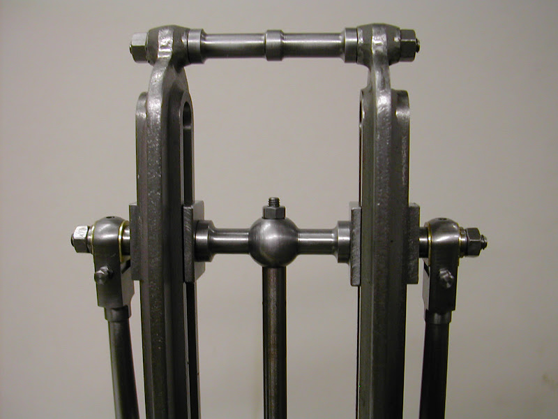
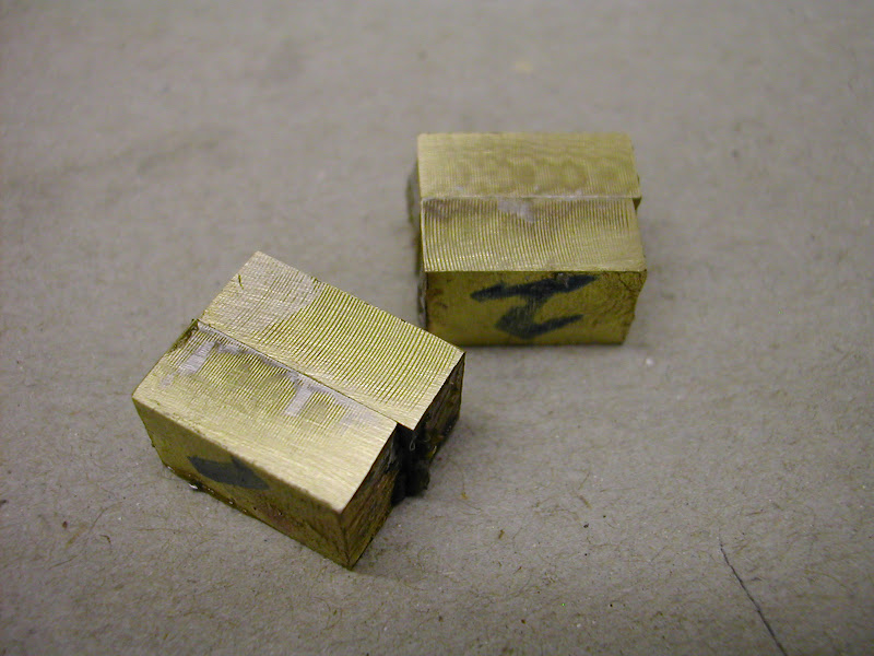
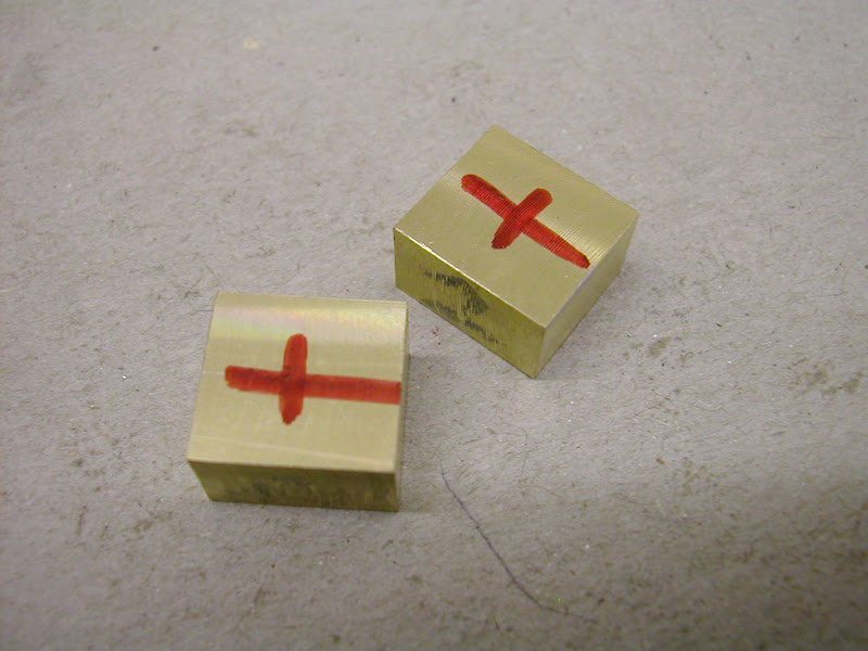
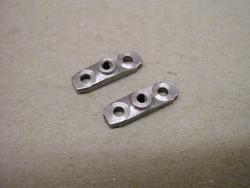
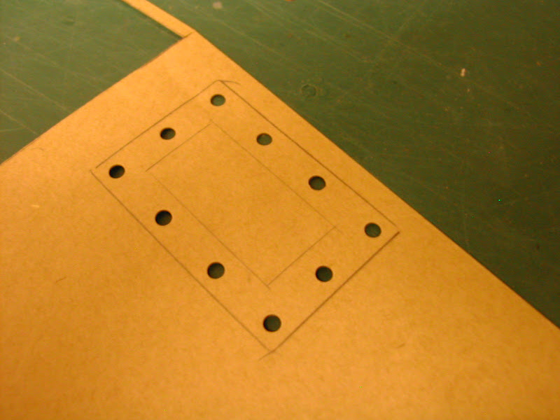
Using these rods as an example but it applies just as well on flat surfaces ....

DSCN3654.JPG

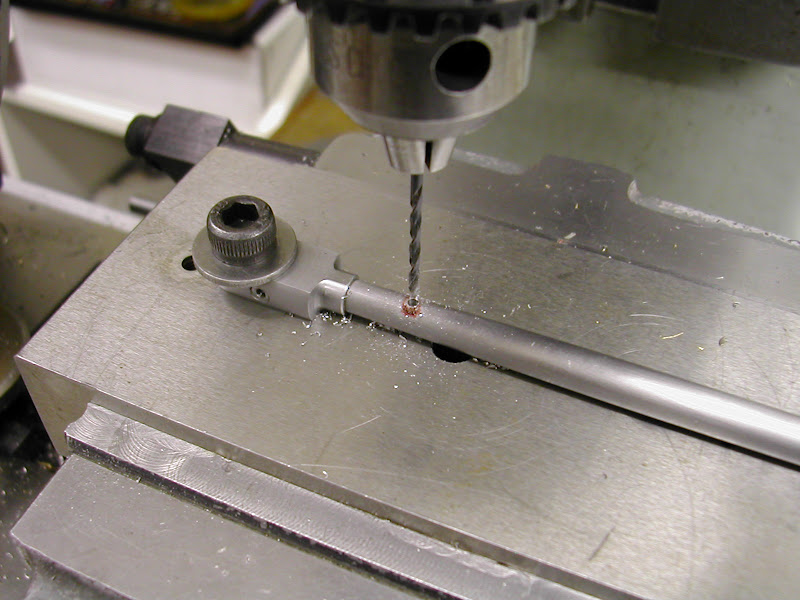
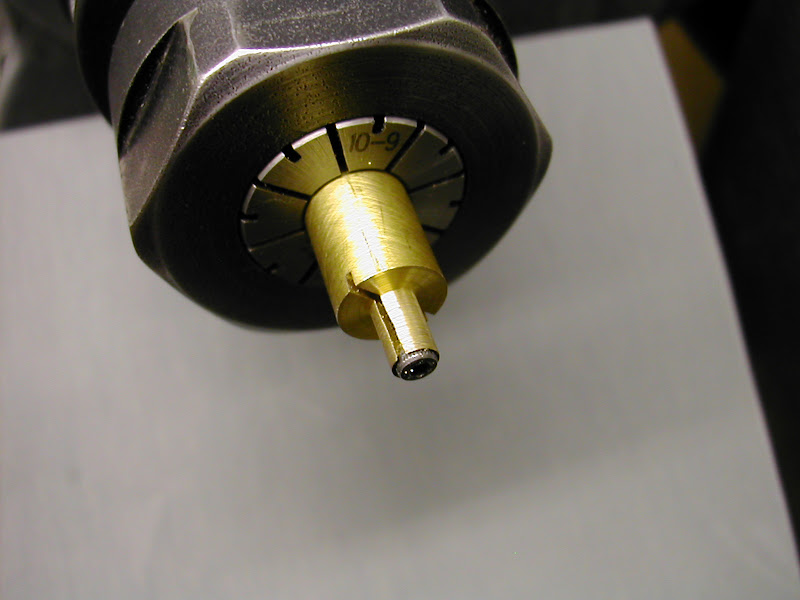
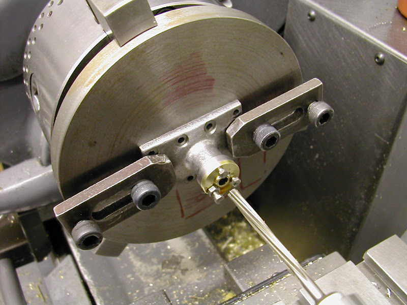
First drill a hole for the pin. Do this with two/three differing sizes the last drill taking out only a few thou. here it was .040 - .055 - .0625 for a 1/16 silver steel pin. To be as invisible as possible turn the pin from similar steel to the part as silver steel will show as a very slightly shinier area on mild steel parts after a while. The important thing is not to deburr the hole - not even slightly. If you do so it will leave a witness.

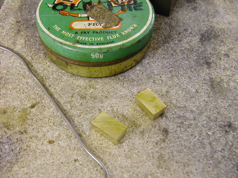
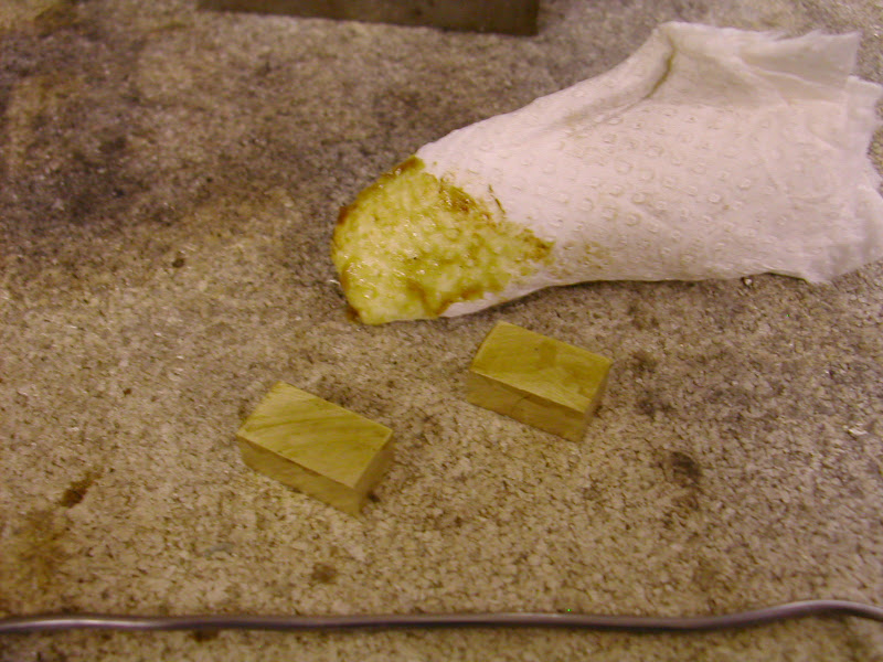
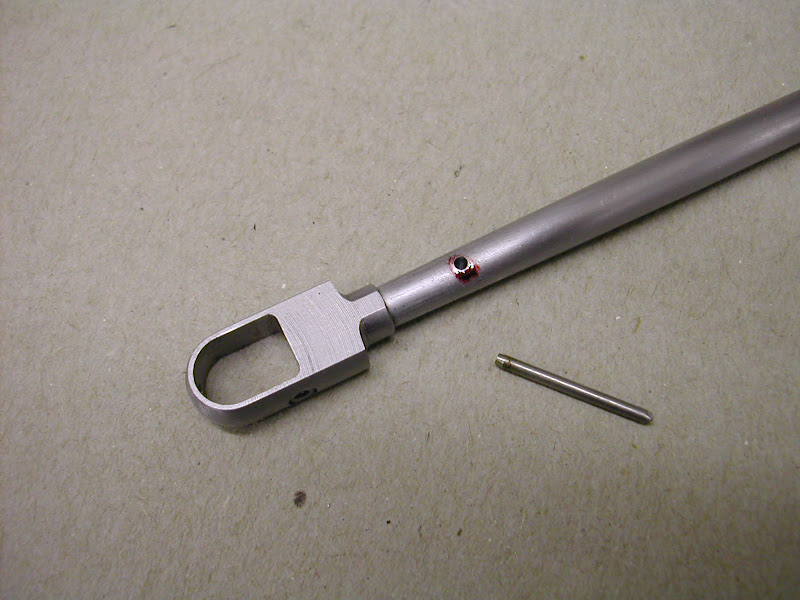
Make the pin long enough to hold and Loctite both the hole and the pin (603 or 638 high strength retainer)
DSCN3656.JPG


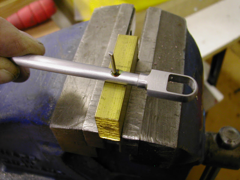
Tap the pin in until it bottoms out supporting it on softer material
DSCN3660.JPG


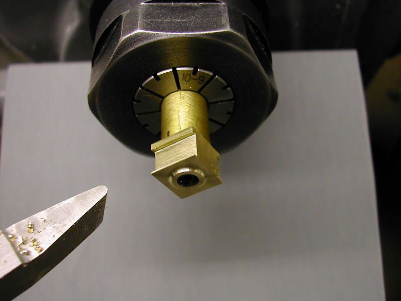
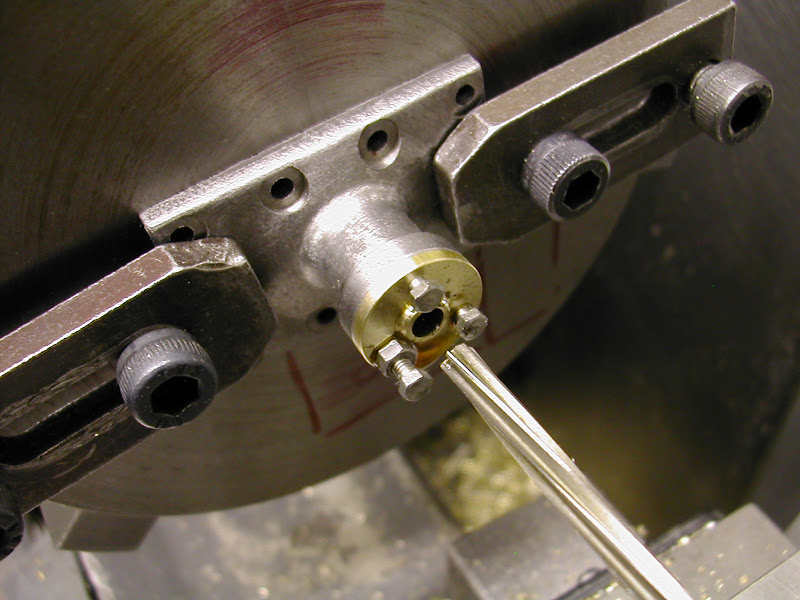
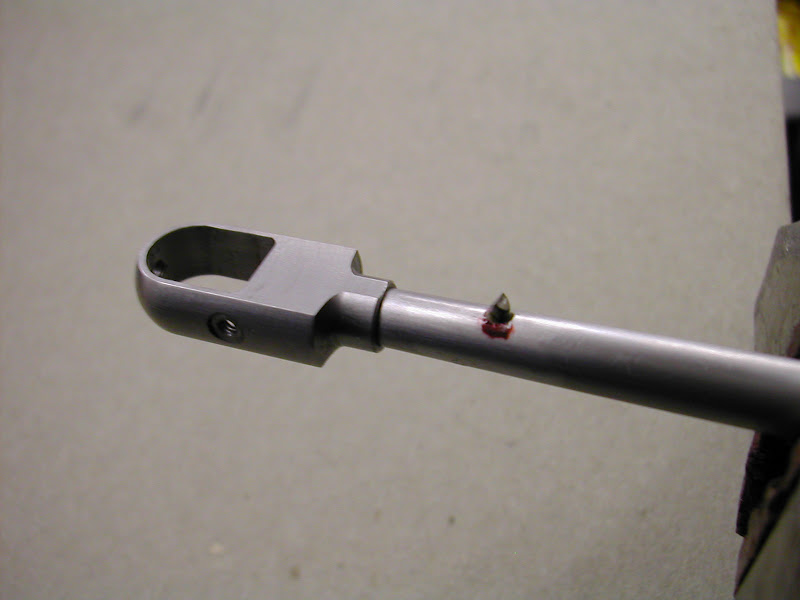
Clip the pin close to the workpiece and gently peen the pin to swell it in the hole. Note 'gently' - don't peen this over like a rivet as there is no need to and you may dent the work piece. (I should point out that I forgot to peen this particular one and it still worked out okay but I would always give it a few taps to ensure the pin fits the top of the hole as tightly as possible.
DSCN3662.JPG


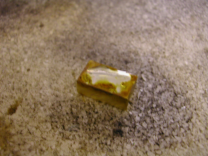
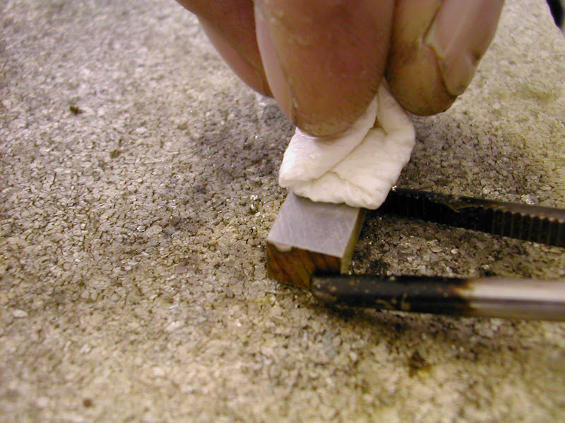
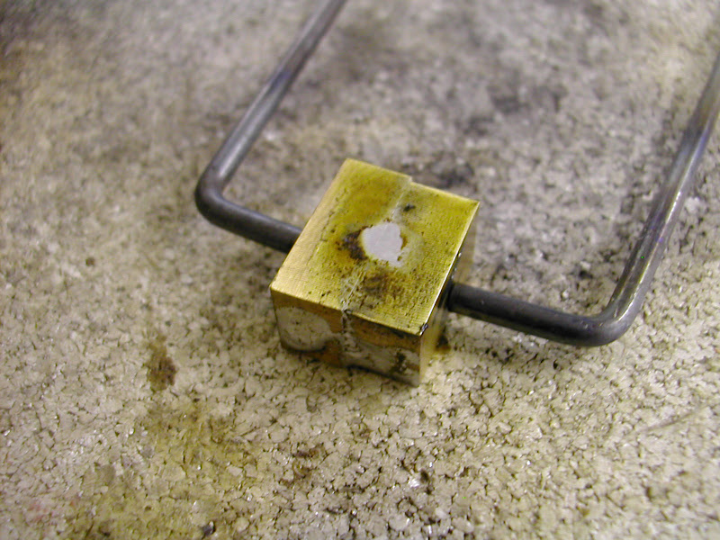
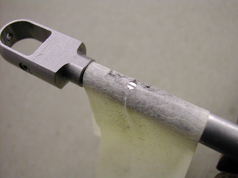
Next pull a layer of masking tape over the protruding pin
DSCN3665.JPG


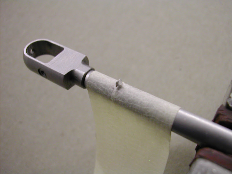
Then using a fine file, file the pin until the file just rubs the masking tape
DSCN3667.JPG


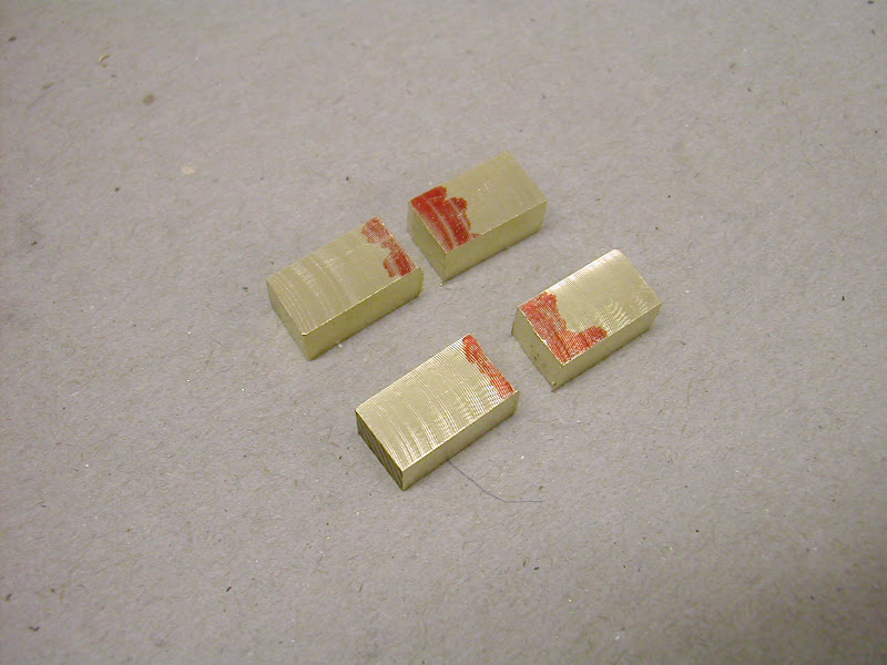
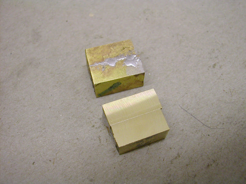
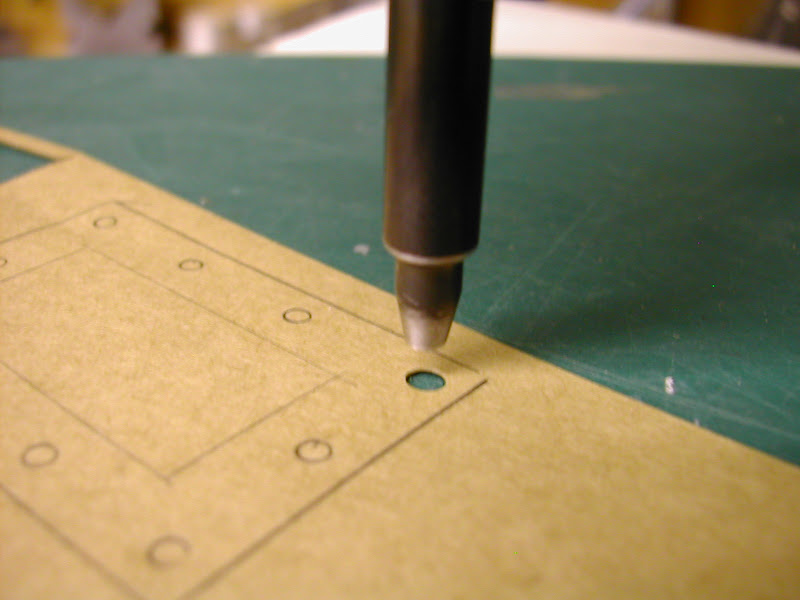
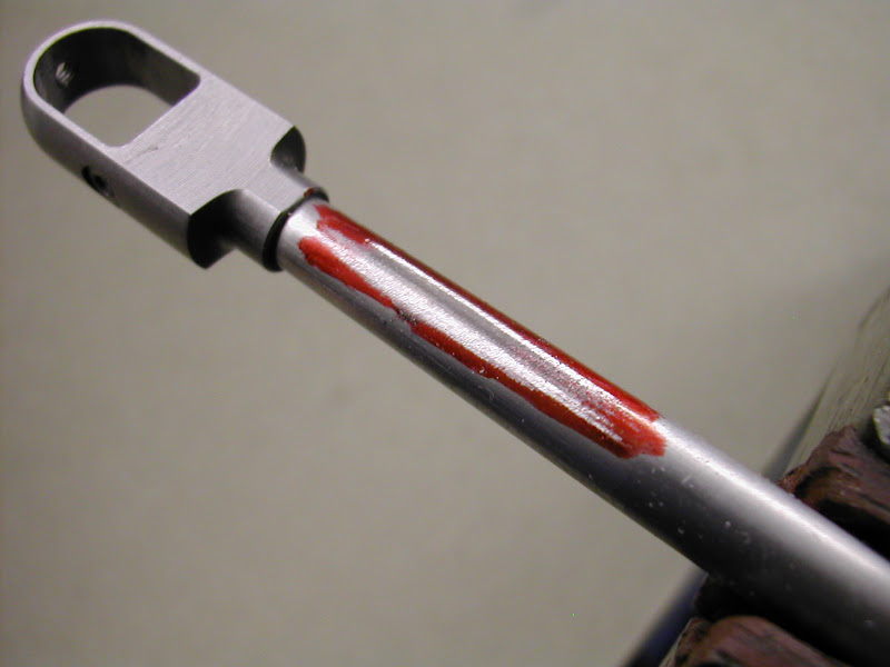
Remove the tape and apply felt tip pen / marking blue
DSCN3669.JPG


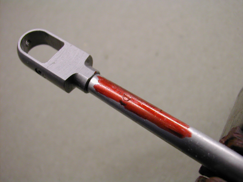
Gently file the pin keeping a wary eye out for marking the ink as here
DSCN3670.JPG


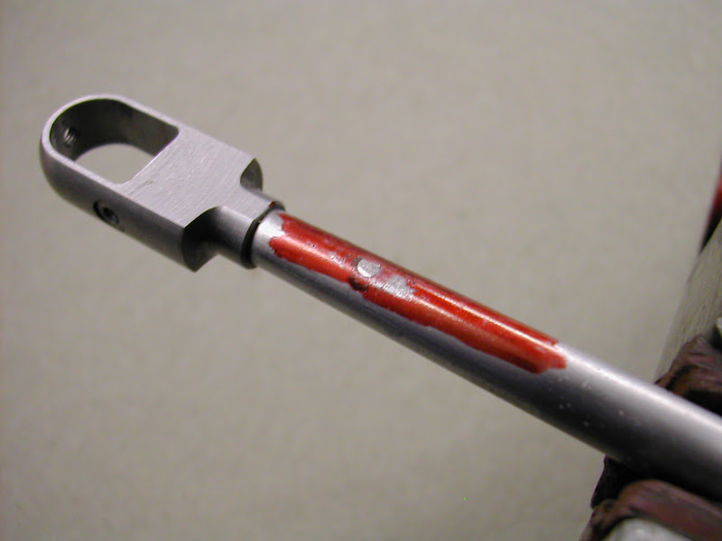
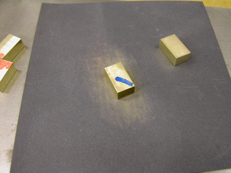
Then file to flair in with the surrounding surface
DSCN3672.JPG


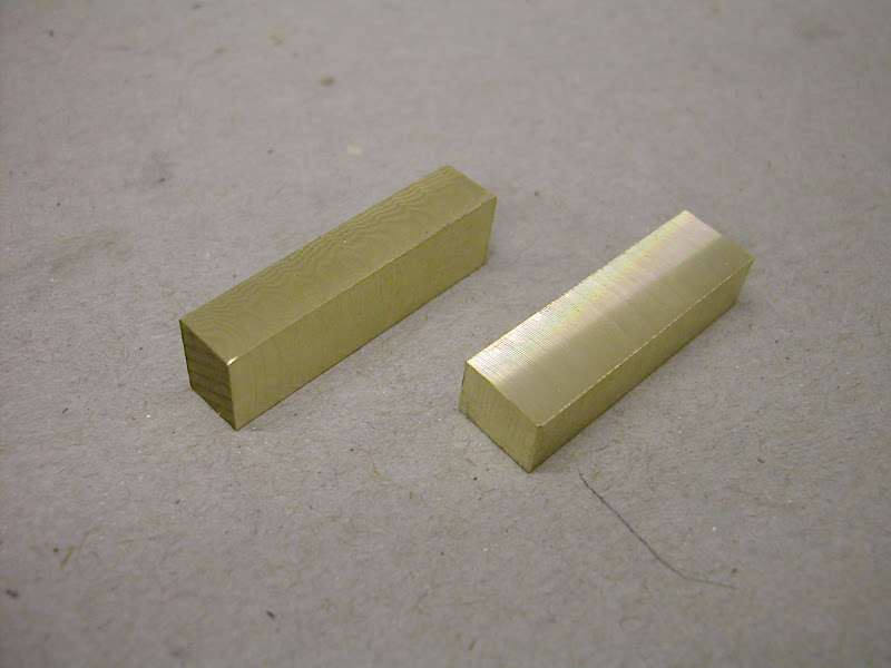
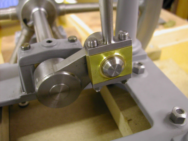
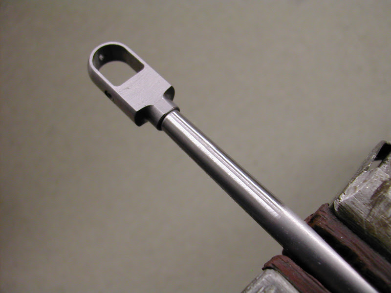
Finally finish with some worn emery. The duller surface on the rest of the rod is the result of using wet and dry and Garryflex abrasive blocks which produes a very smooth finish
DSCN3674.JPG


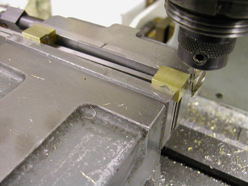
This method works just as well on flat surfaces though the final filing has to be done very carefully to avoid scratching the surrounding area - I prefer to use a flat needle file for that with the very tip rounded off with a stone to prevent corner 'dig ins'. By pushing the end of the file flat down on top of the pin with the thumb of one hand while bending the file up slightly - a needle file will flex sufficiently - and apply filing motion with the other in very short strokes it is surprising just how much control you have in taking the pin down to the surface.

As said - can't stress it enough - if you debur the hole - no matter how carefully - you will get a witness. A little black circle or part of a circle that will constantly yell at you that you really shouldn't have deburred the hole :(

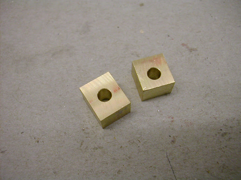
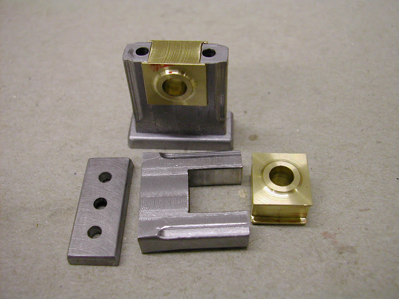
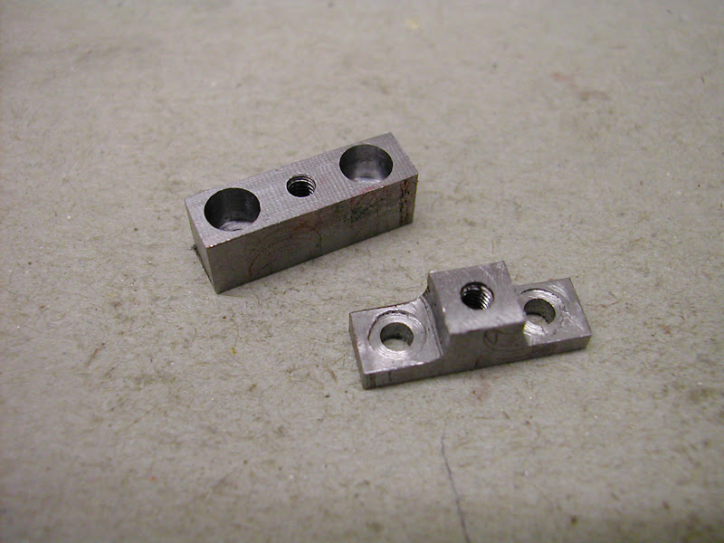
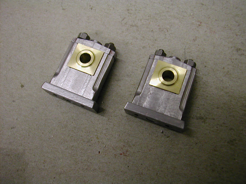
If it's a threaded hole that needs to be reclaimed or disguised it will not work if the thread comes to the top of the hole. No matter how much you peen it there will always be the start of the helix. The only way to totally disguse it is to open it up and plug it as above.

If its done right the only evidence should be a slight discolouration if the materials are different.

Hope that will help improve your pinning Peter

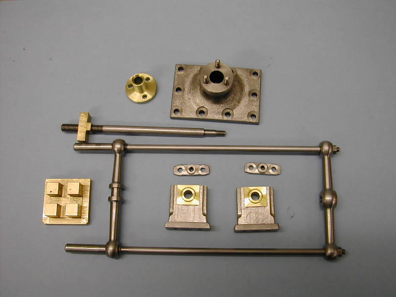
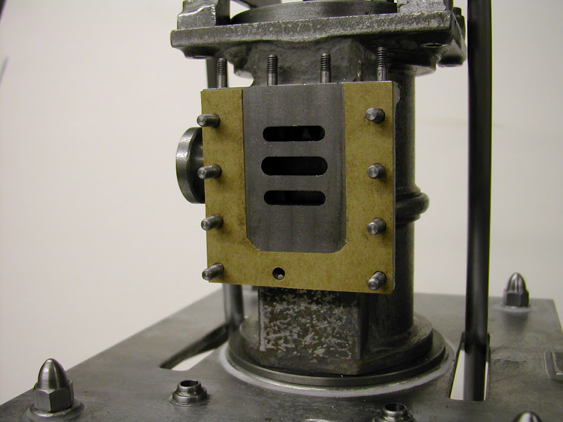
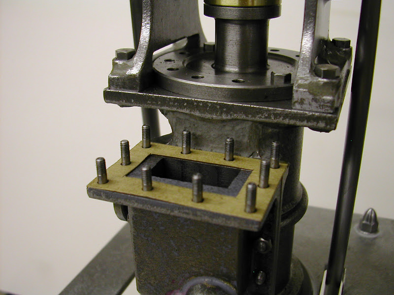
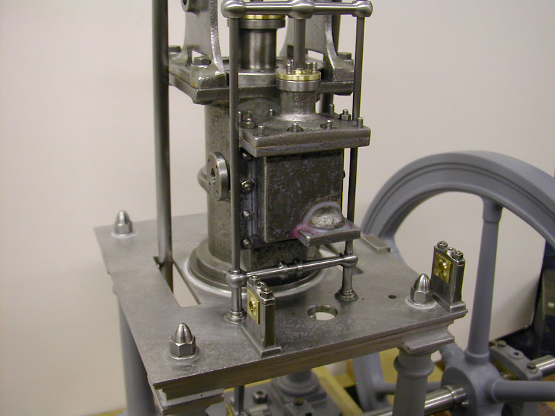
The compressor was plumbed in without half the hassle envisaged so I was able to make a good start on the valve parts - more later

Hope this is useful to others too

Regards - Ramon
 
Ramon,

If anyone says your overdueing this...send them to me...

You just keep doing what you have been doing!...it's awesome!

:bow:

Dave
 
Thanks for the tutorial. Much appreciated. I can see where i've been going wrong. As a matter of habit I always de-burr holes, even if everso slightly.
So I now know what not to do in future.
liked the use of masking tape as a quick way of homing in on the two surfaces when filing.
strangely enough I do use marker pen when filing, but only when I'm filinging two or more flat surfaces to the same size. Never gave it a thought to use it when filing pins down. as you point out, it gives a good indication of when to change files.
thanks again
peter
 
Very nice work. You can never give too long a description of such interesting ways of doing things. The way you did your little end bearings is of particular interest, with the wedge holding them in. I've never seen that before and found it an interesting alternative.

Ray
 

Wow, that sure is some nice work!

Thanks for the detailed descriptions. That wedge sure is a nice touch.
 
Glad it was of use Peter it certainly gives a good result with a bit of care.

The bearing design came from a book I have - one of those lucky but 'rare' finds that sometimes happens when you least expect it. 'Machine Design, Construction and Drawing' has many examples of various parts of engines both steam and early IC. The original A. Mount design appears to have no means of holding the bushes in but I rather liked the idea of the double flanged top portion and the single flange on the lower. The tapered wedge is as shown in the book too but the inner hole to allow the pin to prevent loss is a guess as to how its done. It certainly works though, the bearings are nice and tightly held in place. BTW the actual width across the outer little end frame is 11.0mm (.433) the cavity is 8.0mm (.312) and the bearing hole size is 4.0mm (.157).

Heres a better shot of them fitted, the inner faces have the full flanges ie the lower bearing is inserted from the inner side of the rod.
DSCN3697.JPG


The valve parts are progressing well :) - a few more pics in a day or so if all goes well.

Once again thanks for the kind comments

Regards - Ramon
 
Work continues albeit a bit slower than hoped for but the valve gear is in and moving smoothly and freely. The bearings for the layshaft that operates the valve rod were made today and I took a few pics of the sequence of ops. Now I hope I'm not insulting anyone by showing this basic procedure but I do know that many struggle with soldering so hope this may be of use to someone - if I'm teaching granny to suck eggs here I guess you'll have to look away now :)
The actual bearings are reasonably small - 10 x 9 x 7 mm with a 4mm hole and the sides slotted to locate on the pedestals. I find it much easier to machine the outside to a hole than to put the hole in after the part is finished. That way if there is a slight error creeping in, by making small cuts there is plenty of time to make allowances.

They began by cutting off a short length of bronze from a short slab acquired from somewhere at some stage in years past. It was nice to machine and I would guess it's closer to gunmetal than bronze by the way it machined -it's certainly not 'brass'. It was machined nearly to size in one length then cut in half for finishing to keep any slight discrepancies to a minimum. The thickness (above and below the faces to be soldered were made a uniform but well over size dimension - in this case 6.0mm
DSCN3712.JPG


Each piece was cut in half for each bearing and marked with it's other half
DSCN3715.JPG


The inner faces to be soldered were given a light rub on some 600 grit wet and dry paper laid on something flat. This is a small slab of cast iron ground flat but anything will do as long as it's smooth and flat.
DSCN3717.JPG


These faces - try not to touch them with your fingers after the last op - are then fluxed in this case using traditional 'Fluxite'
DSCN3718.JPG


At the same time fold up a wad of kitchen roll paper or similar and coat with flux
DSCN3720.JPG


The next couple of pics bear testiment to 'Sods Law' - take three pics of each op and you can use 'em all, take one and it's bound to be blurred/out of focus etc ::)

Heat one block at a time until the flux starts to go brown and blob on some solder - this is ordinary multicore -it doesn't have to cover it completely just enough to be able to spread it around.
DSCN3721.JPG


Then while it is still hot hold it with some pliers or similar and using that flux coated paper wipe the solder smooth across the entire face. Flick the surplus solder off with the paper the surface needs to be very thinly coated.
(This pic is an 'after shot' the two done at the time were unusable)
DSCN3728.JPG


Clean off any solder blobs from the sides using a file and a rub on the wet and dry until the faces are smooth again. Lightly rub the soldered face on the W&D to get smooth faces and reflux these and smear together. (They are not soldered at this point merely 'wrung' together with the faces aligned. Note at this point the ends are still as sawn and well over length
DSCN3724.JPG


Using a spring clamp and making sure the pieces are in alignment heat slowly until the melting solder starts to emerge from the join as the clamp pushes the two parts together. Put a very small dot of solder on the top face - this serves two purposes, it makes sure theres sufficient and, as there is a considerable amount of latent heat in the blocks it takes a while for them to cool and the solder to set. By gently pushing this blob (but not, of course, with your finger!) you can tell when that point is reached. If the blocks are moved before the solder sets you can guarrantee they'll move out of alignment ::)
DSCN3727.JPG


Once cooled the fun bit begins to turn them into bearings. The last faces to be machined and only after the hole is put in are the top and lower faces. First cuts are to face the sides
DSCN3734.JPG


Then the ends. Note the use of the second block to ensure uniform clamping pressure
DSCN3742.JPG


The blocks squared up but still with the original top and lower faces unmachined. Marked ready for drilling.
DSCN3744.JPG


After the holes are drilled and reamed those faces can gradually be brought down to block size relative to the hole
DSCN3745.JPG


After the rebates have been milled it just remains to gently file the last .03 or so off of faces to ensure a good fit
DSCN3749.JPG


That's as far as I got today with these, hopefully they will be finished off tomorrow.

Like I said I hope this is of use to someone - I'm not unaware there are some pretty skilled people on here so please - this is very definitely not intended for them ;)

Regards for now Ramon


Great looking engine and the descriptive posts are really informative.

Ray
 
Thanks for all the detail on that last operation. I am definitley here to learn.
 
Thanks for a great description.

Can you add a bit on how you got the hole in the center of the blocks? I have found it hard to pick the exact line of the solder

 
Hi again Guy's,
(in fact it's hi again twice - I've just been adding some more only to click the wrong spot and dumped the whole lot down the swanny Aaaaggghhhhhhh ::)) Oh golly gosh I said or was it something rather similar.

Well it's good to hear that some feel this is worth while - I know what you've said but I'm always at a loss to know whether it's enough, too much or what and indeed suitable but I guess with your input I'll soon get the hang of it :)

Re the hole position Ron and any one else wondering - apologies - that got over looked.
That's the reason the 'top and 'lower' dimensions are a definite and uniform size before soldering and why they are not milled before the hole is put in. By centering the drill on the centreline of the block you are directly over the join line. If you mill these faces before hand there is the possibilty of losing the exact centre line. Once the hole is in the sides can be milled all round keeping an eye on dimensions relative to the hole as milling proceeds.

I've had another good day in the old shed so a few more pics of progress.....

First off was to fit those bearings to the standards using a sharp needle file on the bronze and a used one on the steel
DSCN3760.JPG


Then they were removed and transfered to an expanding mandrel in the lathe. This is one carried over from IC projects. The head is expanded by the 8BA screw which has a 60 degree taper cut on it to match the internal centre drilled taper. These are very efficient workholding devices - infact great care has to be taken in tightening them on this specific operation as it can split the solder join - yes you would be right - but not on this occasion ;D
DSCN3756.JPG


The sides were thinned and bosses turned to improve their appearance
DSCN3755.JPG


Small pads were made for the standards and some rebates milled in to help give a cast look. (The pads will eventually be JB welded to the standards)
DSCN3762.JPG


Bearing caps were made from the same stock as the standards
DSCN3763.JPG


They were then bolted to a mandrel for turning the taper and the oiler boss.
DSCN3776.JPG


Nearly ready to fit - the bolts are dummys - studs as yet to be turned
DSCN3766.JPG


And finally theres a few more parts to fit - doesn't seem much for a several days worth but theres a lot of 'fiddling' in there
DSCN3767.JPG


Well it's getting late and I've got a good book so a bit more on the fitting later

Regards for now - Ramon


Ramon said:
...doesn't seem much for a several days worth but theres a lot of 'fiddling' in there

Looks like several weeks worth of work for me.

Enjoying the write-up, keep it coming.
 
Heres a few more pics covering the few stages to get to current state of play.

The big end was made in a similar fashion to the previous bearings. It is split apart - can't get it on the crank pin otherwise - so you can see the kind of join line acheivable
DSCN3694.JPG

I'm not sure what kind of oiler would be fitted to this kind of big end - I'm considering an oilbox attached to the rod with a thin pipe leading into the top of the bearing - Anyone any thoughts on this?

This has to be one of the most used lathe 'accessories' I have. Just a disc with some 6mm tapped holes in that acts as a quick faceplate for smaller items. The clamps are about 40mm long and are from my very first lathe - a Unimat bought in the early seventies. By setting the top cover to run true and boring the gland in situ ensures perfect alignment of gland to top. The gland must be a good fit in the top though.
DSCN3707.JPG


DSCN3709.JPG


The gaskets were cut from a good stiff brown paper. The pics makes them look as if it's card and rather thick but infact its just under 4 thou and was salvaged from some packing material. They will be soaked in light oil before final assembly.
DSCN3772.JPG


DSCN3779.JPG


After marking off from the part I always cut the holes before the gasket as it's much easier to handle
DSCN3703.JPG


Making a small tubular cutter is easy enough and I used to use it as a wad punch but very often the holes would be misplaced or mis-cut. By running it at low speed in a drill and bringing it down onto one of those self healing cutting mats perfect holes are cut every time.
DSCN3701.JPG


The dimensions on the original drawings are very good - basically I scaled them by 1.333 and made direct conversion to metric. I had to strip it down and re position the holes for the valve rod guides because of that gasket. Anthony Mount certainly did a good job on this engine.

So with all those bits it was time to get it together again and this is what it looks like today. I finally too, after some fourteen years after I made it, got round to fettling the flywheel spokes and primed it.
DSCN3783.JPG


DSCN3785.JPG


I have to take a break from the shed for a couple of days but hopefully next week will see the remaining valve gear parts - rocking shaft and the eccentric drive - finished when it should be able to tick over on air for the first time.

Hope this is still of interest
More later then.

Regards - Ramon

 
Hope this is still of interest
More later then.

Regards - Ramon

Very much of interest, i've been quetly following allong and learnt a lot along the way, some very intersting tecniques show.

Thanks for sharing, looking forward to the next part.

Stew
 
Ramon said:
This has to be one of the most used lathe 'accessories' I have. Just a disc with some 6mm tapped holes in that acts as a quick faceplate for smaller items. The clamps are about 40mm long and are from my very first lathe - a Unimat bought in the early seventies. By setting the top cover to run true and boring the gland in situ ensures perfect alignment of gland to top. The gland must be a good fit in the top though.
DSCN3707.JPG

I really like that idea, should work well with my large chuck. thank you

archer3d
 

That is some beautiful work. The quality really shows through in the close up shots.

Thanks for sharing all of your tips and techniques.
 
I'm really starting to look forward to the video that I hope you plan on posting of it running on air for the first time.

Ray
 
Thank you for showing your techniques. It's always good to have ideas like these, if I can remember them when needed!

Lee


Latest posts

Back
Top