A portable engine

Home Model Engine Machinist Forum

Help Support Home Model Engine Machinist Forum:

This site may earn a commission from merchant affiliate links, including eBay, Amazon, and others.
Hi Jason

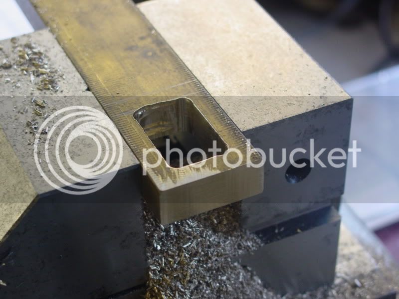
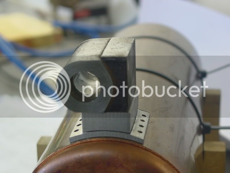
I think I will silver solder the steel block to the saddle and then try screwing that to the cylinder. It should be stong enough. The valve chest and cover will be fitted with studs. There is still quite a bit of work needed to the cylinder that will be easier without the saddle in the way.

Cheers

Rich
 
Hi

A little more progress with fabricating the cylinder today. I decided to silver solder the spacer to the saddle but screw the cylinder on. The cylinder has a nicely honed bore already and I didn't want to spoil it with heat. The steel tube was mounted in the mill and had 3 holes drilled for the fixing screws. I have used 5mm stainless steel countersunk cap head screws for this.

DSC02313.jpg


Followed by 8 holes, 4 each side of 1/8 for mounting the cylinder to the boiler.

DSC02315.jpg


DSC02318.jpg


The spacer has a few centre punch marks to leave a gap between spacer and saddle for the silver solder.

DSC02320.jpg


After cutting out the section from the steel tube it was silver soldered to the spacer. Here it is set up in the brazing hearth fluxed and held together with copper wire

DSC02322.jpg


After a clean up the sides are squared up in the mill

DSC02324.jpg


Then the 3 mounting holes are drilled through 5mm

DSC02325.jpg


And countersunk

DSC02326.jpg


The cylinder has 3 corresponding holes drilled and tapped 5mm

DSC02328.jpg


I had to make a mandrel to hold the countersunk screws to skim a bit off the face and sides so that they would sit below the surface of the saddle

DSC02330.jpg


The parts screwed together

DSC02333.jpg


And sat on top of the boiler

DSC02332.jpg


DSC02331.jpg


Finally today I had a search through my stock and found a bit of 1/2 inch brass that will do to make the valve chest

DSC02339.jpg


Cheers

Rich
 
Oh nicely done, Rich. Terrific fabrication work, it looks like the real deal. Youza!


BC1
Jim
 
Rich is there enough solder in that joint? looking at the last pic there is a gap at the front and you can even see light on the Righthand corner. Probably bot critical as its not under pressure and the screws add support but if it were structural I'd be looking for a bit more solder. Was the wired up photo posed as I can't see any flux.

Also are the holes in the saddle drilled vertically or radially, drill marks suggest vertically in which case your fixings won't sit well but it may just be my eyes.


J
 
Hi

Thanks Jim.

Jason, yes there is plenty of solder in there, It flowed in quite well. Like you say the screws give all the support thats needed. It did occur to me afterwards that it probably doesn't need silver soldering as the 3 screws hold it pretty tight. The wired up photo wasn't posed, there is plenty of flux in there. I fluxed the spacer then sat it on the saddle.

If this trial one turns out ok and is the one I use I may add some fillets in the corners with some JB weld or similar before painting.

The 8 holes in the saddle are drilled radially. I turned the rotary table 19° in each direction.

Cheers

Rich
 
At the end of the day Rich, it doesn't matter how it is made or what it is made out of, as long as it runs and looks the part, and you are perfectly happy with it, what more could you want.

Coming along great there, solving problems as they occur. :bow: :bow:


John
 
Hi John

Thanks. I absolutely love this hobby of ours and couldn't be happier than when I'm in the shop (shame I can't swing a few more hours each week but the senior management has different ideas ::) ::))

The challenge of creating parts from my own design is my favourite part I think, especially when they work :big: :big: :big:.

Julian and I are off to the Harrogate model engineering exhibition this weekend to buy some much needed supplies to keep things going, a good day out.

Cheers

Rich
 
I wish I could be with you there Rich, but I just can't travel that far any more, it is not fair on whoever takes me to stop every 20 to 30 minutes for my sake, so I have now decided to give them all a miss.

We seem destined never to meet in person.


John
 
Hello Rich,

Another great project that you have going again. I have been intently following along.

Not a criticism, just an observation... when you were machining the radius on the saddle with your boring head, the finish that you ended up with would have been much improved if you would have rotated your tool 90 degrees clockwise (looking at the part in the vise with the photo captioned "After cutting.") and ran the mill in reverse so that the top of the tool would have contacted the material first. It looks like it was ploughing the material off the way the tool was oriented. In the end, I understand that it was a soldered surface and finish doesn't matter, but just for future reference.

Excellent work as always.

Kind regards,
Mike
 
Mike, as I pointed out earlier that boring head screws onto the shank so running in reverse is very dangerous as its likely to unscrew, I know I have the same head!!

Would have been best to regrind a tool as the one shown is ground for use in the end of the holder but not really critical in this case as the surface will allow the silver solder to flow into the gap nicely.

J
 
love the fabrication mate

another way with the boring head could have had the tool pointing upright and used normal cutting direction and started cut from the bottom and work up
 
Hello Rich,

I checked to make sure that no one had mentioned this (tool orientation) before I posted, but forgot about the other thread where you were looking for ideas on machining the radius. It appeared to me as if the tool wasn't re-ground for clockwise (normal) rotation and if so, would have presented a blunt edge to the material. Sorry about the duplicity. You had already received great advice from Jason and had it sorted.

Regards,
Mike
 
Hadn't thought of using a old brake cylinder as a "casting".....nice bit a thinking there Rich

I really like the fab job! :bow:

Dave
 
Hi Dave,

the cast iron that the cylinders are made of machines beautifully and the bores are finished to a standard that I would find hard to achieve. Its a fair bit of work to fabricate the engine but the brake cylinders come free so I don't mind.

Hi Mike

I figured something was wrong with the finish I was getting but in this case it doesn't matter so much. I'm not that happy with the boring tools, they were cheap but you get what you pay for I suppose. when I was boring out the holes for the bearings in my high speed head stock for the Myford lathe I made my own tool which greatly improved the finish.

Thanks Browny

John, never say never.

Cheers

Rich

 
Hi

A little progress.

I cut the hole in the valve chest. After machining the end square I drilled 4 x 1/4 inch holes.

DSC02343.jpg


Then joined them up with a 1/4 inch cutter.

DSC02346.jpg


DSC02348.jpg


DSC02351.jpg


The hole doesn't have to be too accurate.

The cylinder and valve chest.

DSC02352.jpg


Cheers

Rich
 
Rich

I think you are making a super job of this build and have followed it from the start.

I would like to have a look at the drawing of this model. Would you mind telling me where you got the drawings for this Portable engine from.

Keep up the good work

Mike
 
Mike, read the first post in the thread details of the drawings that this engine are loosely based on are in there but its being made to suit available materials so is a one off.

J
 
Thanks Jason

Found the construction notes and castings on the Brunell website for the Sissons Portable Engine. Ordered the construction notes

Sorry for the interuption in the thread
 
Hi Mike

No problem, I have sent you a PM.

Cheers

Rich
 
Hi

Drilled the stud holes in the valve chest tonight as per the drawing.

valvechestandregulator.jpg


DSC02353.jpg


Cheers

Rich
 

Latest posts

Back
Top