A portable engine

Home Model Engine Machinist Forum

Help Support Home Model Engine Machinist Forum:

This site may earn a commission from merchant affiliate links, including eBay, Amazon, and others.
Hi

Jason, Thats an interesting technique I'll bear it in mind, thanks.

Dave, if you can find it I would like to take a look.

Jim, I just love messing about with new ideas.

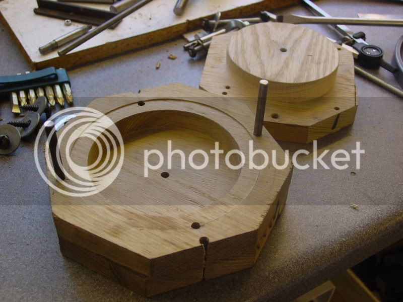
Sneaked a couple of hours today so had a go at another crankshaft. I have used the same jig with a few more holes drilled and tapped so I only had to juggle about with the existing bits.

DSC01812.jpg


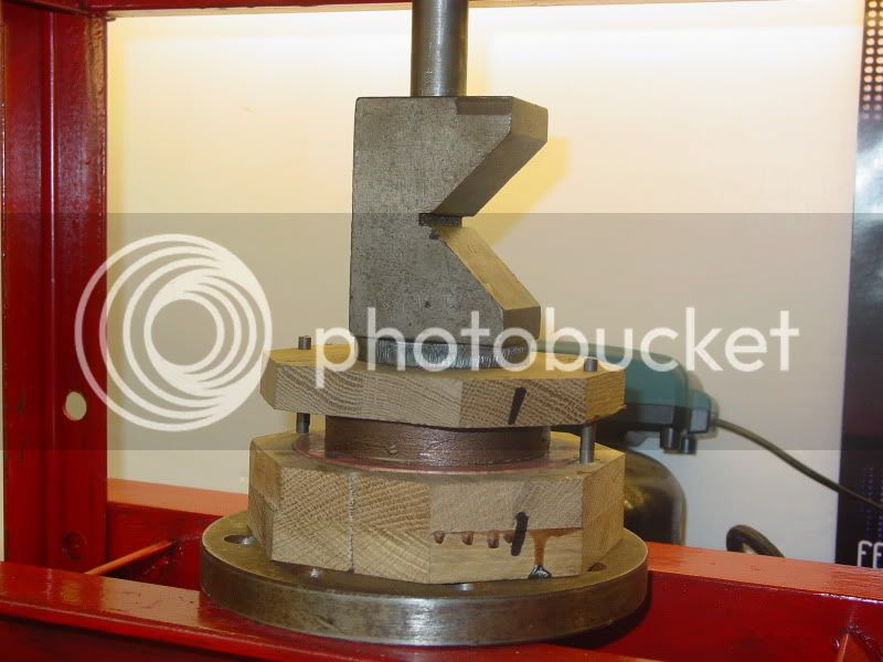
I've used a bit of 3/8 steel bar this time. The first bend I did cold in the press using the 90° point and a matching block.

DSC01814.jpg


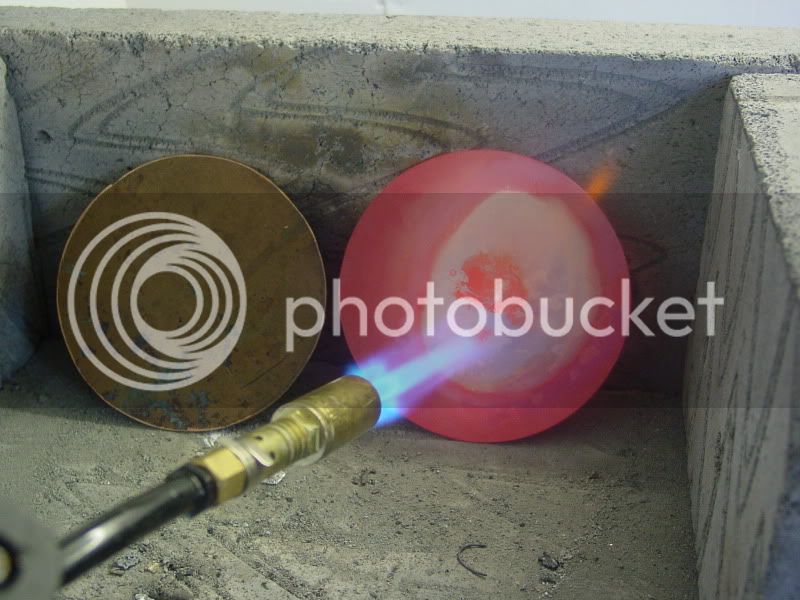
The second bend I did with heat.

DSC01815.jpg


The 3rd bend.

DSC01822.jpg


And the 4th.

DSC01823.jpg


Pretty good but not quite good enough yet. The first and second bends are not equal, they look odd. I have either got to do them both cold or hot.

DSC01826.jpg


Cheers

Rich


Rich if you cold press 1&2 into a flat bottomed "U" shape former with a bit of say 1/2" flat bar thats had the corners taken off that should give you an even tight bend.

Also worth heating the bar and letting it cool first as the annealing will let it bend a bit easier

J
 
Hi Jason

I know about annealing copper, does steel anneal similarly??

Cheers

Rich
 
Yep but don't quench, just let it cool by itself.
 
Ye old type crank shaft manufacture, I love it. It will be a very authentic looking crankshaft.

Brock
 
Hi

Thanks Jason and Brock.

At about the 2 min 50 sec mark in this vid there is JJ seekings portable, very nice.

[ame]http://youtu.be/7urKnVTsujk[/ame]

Cheers

Rich
 
Shame its such a short clip but you should be able to get some details from it.

I know its not teh same style of portable but have you seen this rebuild thread on TT
http://www.tractiontalkforum.com/showthread.php?t=16665
It will only work for members so sign up if anyone else wants to see it.

J
 
Hi Jason

Yes it is a shame but I have found a programme that allows you to down load youtubbe videos onto your own hard drive, from there I should be able to pull off some still shots.

Nice thread on TT but thats not a shed its heaven on earth :big: :big: :big:


Cheers

Rich
 
Hi

I haven't been in the shop for a while but have had the last couple of days in there. I'm keen to pursue the idea of the forged crank so decided to give it another serious go. Crankshafts are one of the main parts of any engine so I figured if I could master it now it would make life easier in the future. heating the metal to red hot then trying to bend round a jig worked to some extent but i wasn't happy with it. I opted for annealing the steel bar first, thanks to Jason for that tip :bow: then cold pressing into shape. We have a pot bellied stove at work so I cut up a handful of 3/8 steel bar and dropped them in until they were nicely red all the way through then took them outand left them to cool slowly at the side of the fire.

DSC01828.jpg


For the jig I used a bit of 50mm x 25mm steel bar, its got to be heavy enough to stand the pressing force. First mill a slot along the top with a 3/8 ball nose cutter to a depth of 3/16.

DSC01833.jpg


DSC01834.jpg


Then mill a slot 1.25 wide

DSC01836.jpg


Make a couple of caps by first drilling some 25mm x 25mm square

DSC01852.jpg


Then chop in half on the band saw

DSC01855.jpg


Drill and tap the jig 5mm

DSC01860.jpg


Drill the caps 5mm and attach with 5mm cap head bolts

In practice it didn't work too well, the crank did'nt form properly.

DSC01867.jpg


However it was straight which was encouraging. The next mod was to machine the slot in the jig deeper and profile the corners with a rotary tool to give a smoother action.

DSC01882.jpg


A piece of the 25mm x 25mm had a slot milled with a 3/8 ball nose cutter almost but not quite 3/8 deep and then drilled and tapped 6mm

DSC01878.jpg


A piece of 1/2 inch square steel bar has two corresponding 6mm holes drilled. When bolted across it will hold the 3/8 steel bar solidly

DSC01887.jpg


I used some copper grease in the slides to ease things.

DSC01886.jpg


This time I just pressed the first two bends.

DSC01890.jpg


Then started the third and fourth bends with a piece of tube.

DSC01891.jpg


One side was then pressed down and held in place with a cap then the final bend made

DSC01892.jpg


After some light tapping with a mallet across two v blocks the crank was put in the lathe and checked and some final adjustments made.

DSC01895.jpg


A bit of video. Note how quiet the new lathe motor is and how slow I can run it.

http://youtu.be/YWh0Hrb-2Ec

Pretty good, I think iv'e got it cracked now.

Cheers

Rich
 
Hi

Thanks Brock

Today I made two little jigs to hold the shaft for turning the journal. I started by facing a bit of 50mm x 15mm

DSC01899.jpg


Then centre drilled the 4 positions

DSC01904.jpg


Followed by a 3/8 drill through the two outer positions

DSC01905.jpg


Cut in half on the bandsaw

DSC01910.jpg


Which gave me 2 jigs

DSC01911.jpg


DSC01912.jpg


DSC01913.jpg


I haven't decided yet whether to soft solder them to the crank or drill and tap each jig twice and fit a couple of grub screws to each

Cheers

Rich
 
Hi Jason

Yeah thats it, thanks I'll save the pictures.

Cheers

Rich
 
Hi

A quick question if I may. I hope to get a couple of hours in the shop tomorrow, what type of tool is best for machining the journal.

Cheers

Rich
 
You can either grind up something like a parting tool with slightly radiused outer corners and relieve the mibble to stop chatter or go at it with alternate left and right hand turning tools blending where the two meet.


J
 
Hi

Got a couple of hours in the shop today so I started by drilling and tapping the jigs for grub screws, 5/16 whit.

DSC01915.jpg


DSC01917.jpg


DSC01918.jpg


One of the jigs will have a long grub screw to make it possible to attach it to the face plate.

DSC01920.jpg


DSC01922.jpg


The jigs are set between centres and the journal checked with a DTI

DSC01921.jpg


The journal ran out slightly, about .020, but that was due to the bends being not quite right. I machined the journal with a rear mounted parting tool which worked ok. The finished journal ended up at .291 which is not too bad.

DSC01930.jpg


DSC01932.jpg


Overall not too bad for a first attempt. I'll give it another go as and when time permits and try to refine it a little more.

Cheers

Rich
 
Hi

Well its been a while since I posted any progress (domestic duties :( :( :() but I did manage the afternoon yesterday. First thing I did was to mount the boiler tube in its holding jig and trim the ends square in the band saw.

DSC01970.jpg


DSC01973.jpg


DSC01975.jpg


As I am not following the plans to the letter but allowing myself to run freelance I was going to increase the boiler length to around 9 inches or so. Looking at the tube I decided to leave it at its length of 11 7/8. Chopping off a piece @ 2 7/8 would be a waste and would result in a useless length of 4 1/4 dia copper tube so why not leave it on and make a bigger boiler and more substantial model. So for the time being it can stay uncut.

A Drawing

DSC01978.jpg


Cut out a couple of pieces of .083 copper plate on the band saw and file to size.

DSC01991.jpg


I decided to make a punch and die to form the end plates, a method I used very successfully on my other boiler. They can be made quite quickly. If you use the method of beating it over a former you still have to make a former. The previous nigt I glued together some 20mm thick hardwood off cuts, oak I think, into pairs. They were held under pressure in the press.

DSC01963.jpg


Drill the centre 6mm

DSC01981.jpg


Mark out

DSC01982.jpg


Cut the corners off to clear the lathe bed

DSC01984.jpg


Mount on the face plate with 2 6mm studs using the tail stock centre to align it centrally on the face plate

DSC01985.jpg


An old wood chisel ground up as a tool.

DSC01990.jpg


Having cut the hole to size about 20mm deep I had to screw the die onto the face plate from the rear and remove the studs.

DSC01992.jpg


Which allowed me to cut the recess for the copper disc to sit in for alignment

DSC01994.jpg


DSC01995.jpg


The punch is turned in a similar fashion

DSC01997.jpg


The punch and die are bolted together through the 2 central 6mm holes then have 2 6mm holes drilled on the edges for alignment pins and the two sides marked to aid alignment.

DSC01998.jpg


DSC02000.jpg


DSC02002.jpg


DSC02001.jpg


Anneal the two copper plates

DSC02005.jpg


DSC02006.jpg


DSC02007.jpg


The punch and die have a generous coating of copper grease

DSC02008.jpg


DSC02010.jpg


DSC02011.jpg


Then with the plate sitting in the recess and the punch and die assembled its over to the press.

DSC02014.jpg


Thats the first one done

DSC02016.jpg


The second one was pressed similarly then into the pickle bath for a clean up.

DSC02022.jpg


Back in the lathe held on the punch with tail stock pressure on a scrap of hard wood

DSC02023.jpg


Trimmed to size (7/16) with a parting tool

DSC02024.jpg


DSC02026.jpg


A very light skim and they fit perfectly

DSC02028.jpg


DSC02033.jpg


A very satisfying afternoons work

Cheers

Rich


You've really got the hang of this boiler making now Rich, there's no stopping you.

Did you ever get to use that bit of tube I sent to you a few moons ago? I always wondered what you managed to make with it.


John
 
Hi John

No Iv'e not used that yet. Its too good/not needed for something like this project. My eventual plan is to build a traction engine which it will be perfect for with its thicker wall. A few more skills to be learned first but don't worry John its sitting there in line waiting its turn.

Cheers

Rich
 
Hi

Well its been a while since I had any shop time but the decorating is nearly done now so I'm getting back on track.
With a piece of 2 1/2 inch 10swg (1/8) copper tube now sourced for the firebox I decided to have a go at pressing the firebox tube plate, also 10swg (1/8) copper plate. I have used the same method as for the boiler end plates, I was keen to know whether or not the thicker plate could be pressed just as well.

The punch

DSC02059.jpg


And die

DSC02060.jpg


I made in a similar fashion to the boiler end plate punch and die out of hard wood.

A piece of 1/8 copper plate is cut out then filed to size

DSC02063.jpg


Until it is a nice fit in the machined guide recess in the die

DSC02069.jpg


The punch and die have guide pins fitted.

DSC02070.jpg


Plenty of copper grease to ease the pressing operation

DSC02072.jpg


Over to the press the copper plate, after annealing, is mounted in the punch and die

DSC02073.jpg


I stopped about half way through the pressing and re annealed the plate then pressed it in all the way

DSC02077.jpg


Not bad

DSC02079.jpg


It only needs light fettling now

DSC02084.jpg


I was pleasantly surprised how well and easily it pressed.

Cheers

Rich
 
Back
Top