90 degree V-twin engine

Home Model Engine Machinist Forum

Help Support Home Model Engine Machinist Forum:

This site may earn a commission from merchant affiliate links, including eBay, Amazon, and others.
Very nice, George. It's fun to watch you work.

Chuck
 
Will you be at Cabin Fever? If so will you be bringing that work in progress? I'd love to see it in person. Very nice!
 
George, Like others here I have been following your build. This is magnificent work. I seem to learn something with each new installment as you post.

Once I get moved I need to get a set of those 'Kant Twist' clamps.

Thank you.

 
Jadecy, I would like to go to Cabin Fever. The last time I went it was in a snow storm so I'll have to wait until next week to see what the weather looks like.
gbritnell
 
Great work George :bow: :bow:

I'm having problems visualising the scale of the engine would it be posible for you to post a pic with a rule in vew to give me some idea of size.

Thanks

Stew
 
Hi Stew, this picture is for you. I layed out some of the parts I have made till now and took a shot with a 6" scale.
gbritnell
GQ.jpg
 
Today I started on the camshafts. They are made from W-1 drill rod. (water hardening)
I turned both blanks on on piece of .50 dia. rod. The one with the threaded end will be the shaft that operates the ignition. The front bearing surface was turned to size .25 dia. and the lobes were roughed out (width). I indicated my dividing head to get everything true and clamped up the first blank. As is my normal procedure for making cams, I lay out the lobe in AutoCad and calculate the steps that will be needed to profile the shape. I then make a chart for each lobe, one step for rotation and one for depth of cut. I start at -O- with my dividing head and rotate around till I get back to the starting point. I then rotate the head to the next lobe centerline and start my cuts again from that angle, not -O-. Once I have my first chart it's just a matter of adding the dimensions to the lobe centerline angle. This is one of those jobs where you have to pay close attention to where you're at. If you have a brain fade you'll be starting over.
GR.jpg

GS.jpg

GT.jpg

GU.jpg


After stepping off both lobes I went to the split angle between them and put in a .062 diameter hole for a dowel pin. This will be my key for the slot in the gear. I am also going to drill and tap a 0-80 hole into the shoulder behind the gear to keep it in place.
GV.jpg


The next picture is the other shaft being cut.
GW.jpg
 
From the mill I went to my small lathe. I chucked the piece on the far end and supported the other with my live center. My chuck runs out about .001 so by the time I get out about 6.00 to the center the runout is negligible. I then cut the inboard bearing surface. I didn't want to cut it when I first did the shaft because I might have got some chatter when I was milling. The next picture is the cam blank machined.
GX.jpg

GY.jpg


At this point I leave the cam on the bar to use as a handle for finishing. I paint over the cam surface with a marker so that when I start filing I can see where I'm removing stock and that I'm staying parallel to the shaft axis.
GZ.jpg


The next couple of shots show the lobe after lightly filing it. I just rest a good sharp file on the lobe so that I keep everything parallel. As I'm filing I rotate the shaft so that there is a nice blend between the machine cusps.
HA.jpg

HB.jpg


The last picture in this set show all the tool marks removed by filing.
HC.jpg


The last two pictures in this set show the cams, polished and cut off from the bar and with the gears slipped onto them. By the middle of the coming week I should have the bottom half of the engine complete. I'll start on the cylinders after the lower end is finished. I usually do the cylinders and then the pistons. It's easier to remake a piston than a cylinder. I have a stock of piston rings from when I built the Holt. They were 1.00 diameter also. I probably won't post any more until I get to the heads, there's not much to see in cylinder turning.
George
HD.jpg

HE.jpg
 
George,
I know I've said this before, but...Wonderful job! Thank you for taking the time to show these fabulous posts.
Dennis
 
gbritnell said:
I then rotate the head to the next lobe centerline and start my cuts again from that angle, not -O-. Once I have my first chart it's just a matter of adding the dimensions to the lobe centerline angle. This is one of those jobs where you have to pay close attention to where you're at. If you have a brain fade you'll be starting over.

George, for the second lobe, (reading the quote above), you mean you add each number on your chart to what ever the starting angle of that second lobe was, is that correct?

Then keep adding or subtracting, according to the same chart you used for the first lobe, but always using the second lobe angle as your base number, right?

This definitely sounds like one of those setups where I would write down every step before starting, or I'd be doing the job more than once!

As an aside, I'm sure if you decided to take photos of the cylinder work, no one would mind. : )
(I know it takes time from the shop work, though.)

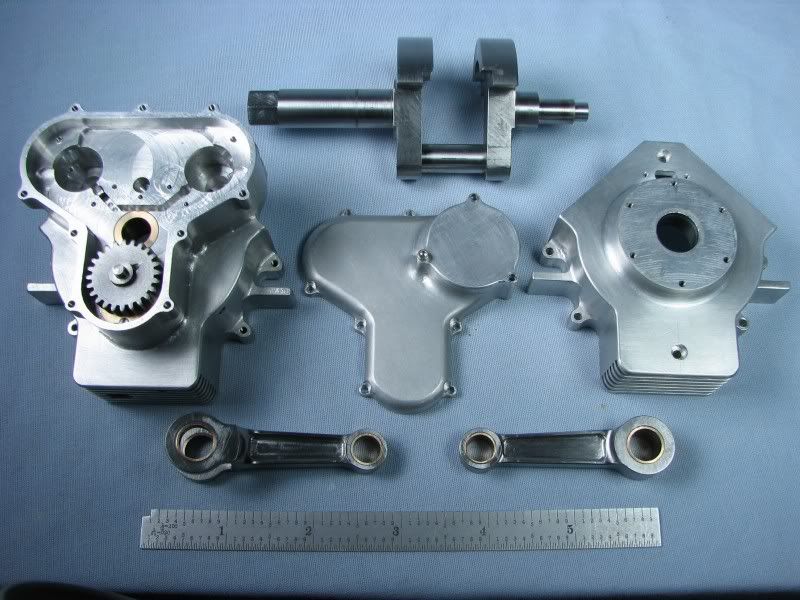
Thanks again for this write up, and for the pictures. The progress shot with the rule helps show the scope of the project.

Dean


Hi Dean, you're correct. I start at the centerline of the first lobe and step around until I get back to -0-. My next lobe centerline is 135 degrees apart from the first one so 135 is now my -0- and I just add all of the dimensions from the first lobe to 135.
I have the oil pump gears fitted so when I get the rest of the gears keyed and mounted in their bushings I'll take a picture of the gear set. It's not a problem to take pictures of the cylinder machining I just felt that there wasn't much to see. Most of the modelers on the forum have turned a cylinder at one time or another.
George
 
I think they just want to see how you "Skin this cat" George. I'm a foreman in a machine shop. I've found that you can give the same job to ten different guys and all ten will go about the same job in a different way. But they all "usually:eek:)" end up with the same part.

They just want your "take" on machining a cylinder:eek:)
 
George;

+1 on Powder Keg's comment!

I'm also curious about the toolbit shown in your photo of cutting the inboard bearing surface. It's got such a small included angle, smaller than I'm used to seeing. Is this a tool form you've used for specific jobs/materials? Any rake/clearance angles?

Also why W-1 rather than oil or air hardening? Or is this a case of "I had some!"

Great WIP, I'm all eyes and ears.

Cheers
Garry
 
Just to clear this in my head re the cams. Is it true that for each cut you are adjusting the tool height and moving the table in the x-direction?
 
The tool doesn't have any top angle. This was the only tool I had that was narrow enough to get into the space and cut up against the right hand shoulder. I have some tools ground up for cutting to the right with top rake on them but they were too wide and I didn't want to destroy them. I used water hardening drill rod because I find it easier to cut then the other two.
For each cut I adjust the Z depth and in this case I'm moving the table in Y, across the lobe.
George
 
Hi George

Thanks for posting the pic with the rule, I've got the size firmly fixed in my head now, its larger than I was thinking. (love the nibble out of the rule by the way :big:)

Some great posts and information on making the cams, I realy must have a go at a IC engine one day, its the ignition system that puts me off, I realy can't get my head round that part.

Watching with interest.

Stew
 

Latest posts

Back
Top