Wyvernish Build

Home Model Engine Machinist Forum

Help Support Home Model Engine Machinist Forum:

This site may earn a commission from merchant affiliate links, including eBay, Amazon, and others.
Hi Gus.

You are getting well on with the Wyvern I like the water cooling set up and the fuel tank, it's starting to look the part, looking foward to the running stage.

Although I have my Wyvern finished I look through your threads and get some good info on the way you went about some of the operations in the build, which makes me say "why didn't I do it that way"

Mike.
 
Phil, Thanks, it's getting there.
Sponge Bob pencils: made for kids, 13mm lead, hard to break, I have dozens of them. PRETTY GOOD FOR DRAWING STICK FIGURES:D The erasers aren't worth s...! Also not so good for finer work.

Hi Mike, It's almost done, pretty much right now it needs an ignition.

"why didn't I do it that way"
Almost every time I check out other people's posts.
 
It is build threads like this one that teach me how little I actually know about making things. Truly inspiring work :bow:
 
It is build threads like this one that teach me how little I actually know about making things. Truly inspiring work :bow:

I've been a TV aerial engineer for 13yrs (after 13yrs as a CNC turner) and if it's taught me one thing, it's that there are 2 dozen ways to get to the same result. It all depends on what you are taught, and the tips and tricks you pick up on the way.
 
HI
Have just posted a reply in Ignition circuit help thread about a cheap ignition system for my Wyvern for £7-69p which i obtained from ebay.

Hugh
 
Brian, thanks for the kind words.
I get real satisfaction out of utilizing things on the junk pile.
Like Woodster said, there's a lot of roads that go the same place.

Hugh, Thanks for the heads up. Sounds like a good idea. Might try it someday.
As for this engine, I made a magnet wheel for a Hall sensor, it will be mounted on the side shaft and will hide behind the flywheel.
I used the Hall type ignition (S&S) hidden in a scale model coil box to run both of my other engines. I just move it from one to the other, and now this one. Works for me, no physical contact.

DSCN1523_zpsad1aa815.jpg


DSCN1524_zps80662c76.jpg


DSCN1525_zps1f4eae9f.jpg


Batteries are NOS, a friend dropped them off at my place one day.

GUS
 
Plumbing the fuel tank.

After sketching things up I started out with the compression fitting for the fuel line.
Both ends of a cut to length piece of the ¼” SS tubing were reduced and threaded 10-32.
Then in the mill vise at 45 degrees the sawed in half at what I figured would be dead center (mostly a guess) to form the two halves of the miter.

DSCN2975_zpsddf395cc.jpg


Silver soldered and cleaned up a compression nut was made.

DSCN2978_zps73e306f2.jpg


The other threaded end is my version of a pipe thread. It'll do.

I made one of these fittings for my Lil’ Brother. it works well.
I use a small segment of Teflon as the ferrule.

Next in line was the check valve using the same SS tubing.

DSCN2976_zps2d945833.jpg


The tank “flanges” were also made. One each for the outlet, filler and vent.

DSCN2983_zps97383bb5.jpg


The filler wasn’t made yet in this picture, but it is of similar construction.
A basic tube with a loose collar curved to the radius of the tank.
The collars were Loctited in place, and after setting, the flanges then Loctited to the tank.
Theory being the collars more than double the contact surface for the glue.

I built the fuel thank for Lil’ Brother entirely as a glue up, including the tank ends, and it’s still holding perfectly some two years later.

DSCN0683_zps8e45443a.jpg


DSCN0682_zpseba1345d.jpg


All the Wyvern fuel tank pieces now complete, except the filler cap,
DSCN2982_zpsbb85eb1a.jpg
 
Great work Gus. Maybe I'll see it running at Cabin Fever, eh?

Phil
 
Then the fuel tank assembled.

DSCN2984_zps6cb6348b.jpg


DSCN2986_zpse944b3dd.jpg


The plastic fuel line is temporary (for start up purpose only) and will be replaced by a 1/8” SS tube after the engine is running good and assembled on it’s permanent base.

Next day I discovered this.:eek:

DSCN2987_zps6eb8d914.jpg


Too much torque on at least one of the nuts, I wasn’t counting turns, just tightening, big mistake.
The seal is formed by a 1/16” O-ring between the glass and the tank and padded with a paper gasket between the cap and the glass.
I think tightening carefully in sequence will prevent this from happening again.

Four new glass caps were made. Quite a bit rougher cut (old glass from a storm window), but I got all four pieces without any breakage.

DSCN2989_zpsa815acf2.jpg


Reassembled and torqued evenly the tank was filled with water for an overnite test, no leaks.

DSCN2990_zpsbe7f54c1.jpg


DSCN2992_zps2293ec0e.jpg


The grandkids pics behind the tank just for the fish(halibut/heluvit:rolleyes:).
They were having fun at an engine show riding around in the back of my buddy’s “Hoofty” wagon(Cushman type vehicle).

I couldn’t resist flipping the flywheel to see if it draws, yes, it does. Now I think I have to pump the water out of the cylinder.:p

I finally made the fill cap, same design as the vent, which was the result of an “oopsy” when I was free handing a light taper on the lathe, using a ball end mill for a cutter.

I had in mind something like a pipe cap, but salvaged this shape from the already threaded vent cap. Kind of different, I believe I’ve seen a similar shape used for a governor shield. Works for me.

DSCN2995_zps2080e83f.jpg


There's only a few things more to do before I go for "THE BIG START UP"
Which I'm very apprehensive about.:hDe:
 
Last edited:
Great progress Gus!

Thanks for the update.

Dave
 
Can't wait Gus. Keeping my finger crossed so that it does not give you any trouble.

Vince
 
Phil, you kind of snuck in between my back to back posts, I was surprised to see it there.
Yeah, I'm aiming at Cabin Fever.

Guys, thanks for the encouragement.

GUS
 
Almost going real time now, I’m getting caught up.

I filled the fuel tank with Coleman fuel, it’s been about three days now and holding perfectly, no leaks.

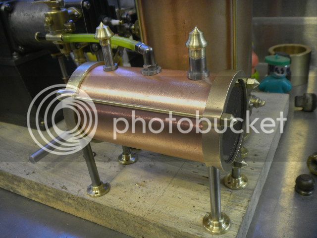
I sealed the cooling tank and tested it overnite, it had small leak which seemed to be from the bottom of the soldered seam. Not unusual, I’ve had that happen before. I put a coat of fuel tank sealer on the inside of the entire tank and it’s now holding water.

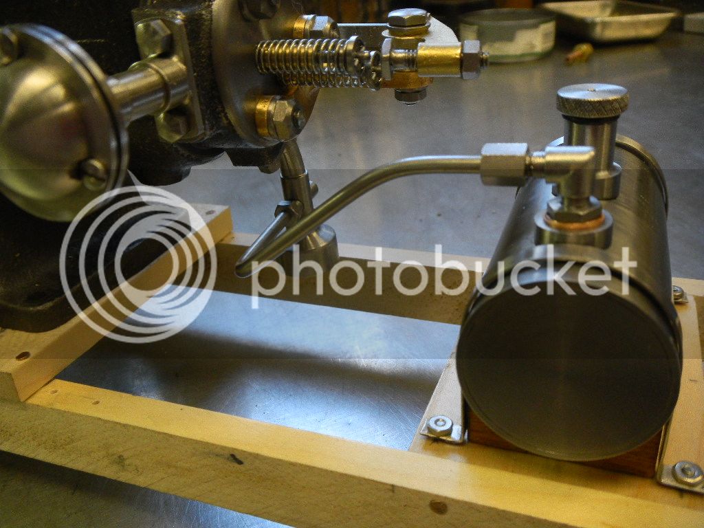
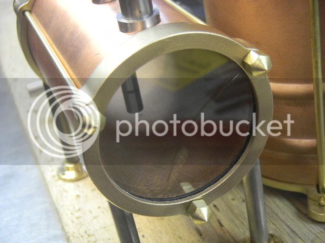
That first water test complete it was the time to test the rest of the piping and the cylinder to liner.
For this the cylinder head was removed so I could see that joint. With the cooling tank attached and filled, about an hour later no leaks. Good show.

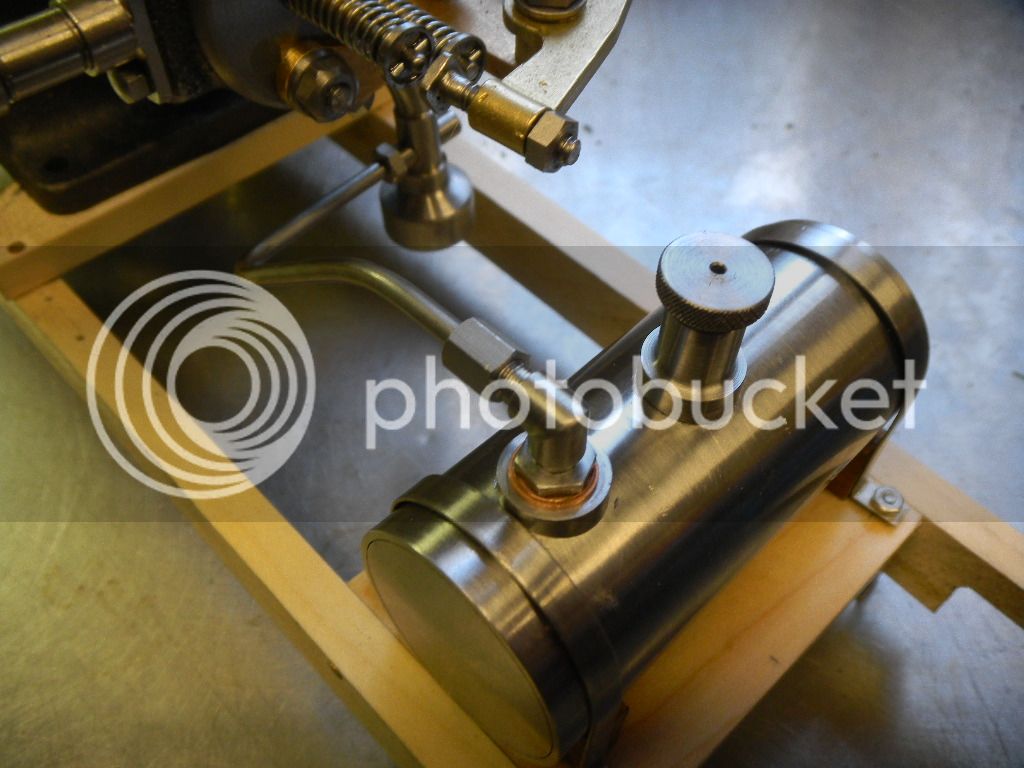
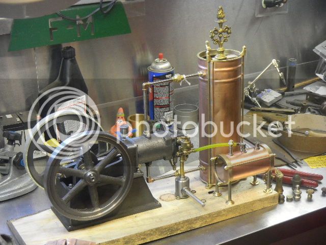
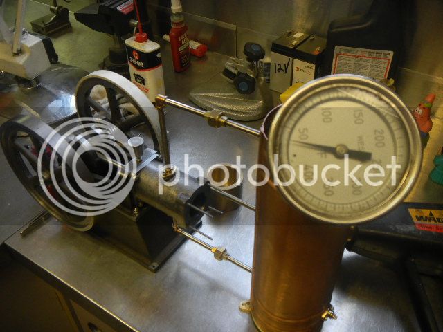
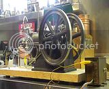
While it had water in it I figured I might try a preliminary test, to see if the water would thermosyphon when the cylinder was heated.
For this I used a heat gun set on low and propped it up to blow directly into the cylinder.

DSCN3023_zps832f9af1.jpg


I also dropped a thermometer into the tank to give me an idea of the rate of flow.
The gauge is bottomed out which is about right. This time of year the our well water is really cold about 45 deg.

DSCN3013_zps983fda6b.jpg


With the heat gun running about ten minutes, there was absolutely no flow although the cylinder was almost too hot to touch.
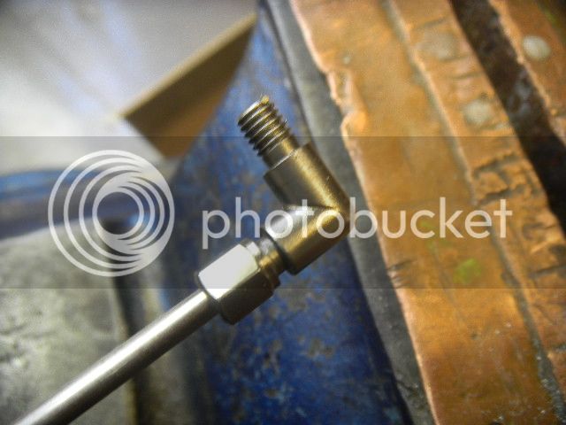
I noticed an air bubble in the end of the inlet pipe, telling me it might be air bound so I tipped the engine and tank back a bit and a string of bubbles came out, followed by some fairly warm water.
That made me smile a bit.:)

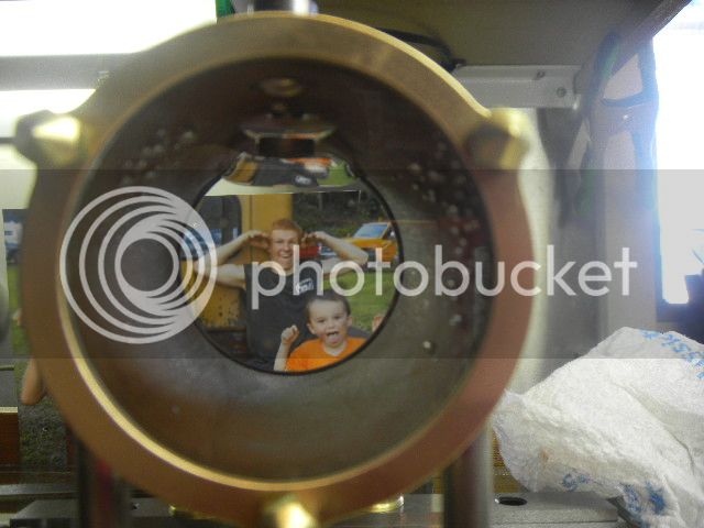
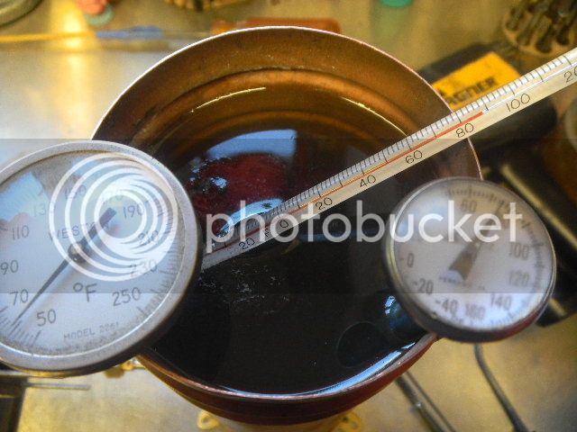
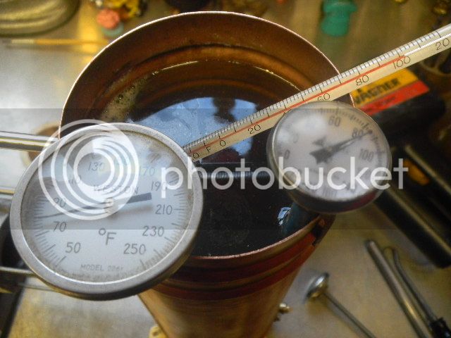
If one thermometer was good, three would be even better.
About an hour into the test, this was the result.

DSCN3019_zps267f2e25.jpg


The glass thermometer was right below the inlet reading almost ninety.
The probe on the little one was about halfway down and the probe on the big one almost at the bottom.
Water was flowing and the cylinder was cool enough touch, even though the heat gun was heating more than just the inside of the cylinder.
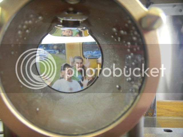
And about another hour things were a bit warmer but not alarmingly.

DSCN3025_zpsc3dc81eb.jpg


I’m thinking that I should to be able to run the engine some time and not overheat it. I’ll find that out for sure when it is running.
 
I ran the test for another twenty minutes or so with not much increase in temps, and decided there was nothing further to prove. I’m happy.
After another hour, all the thermometers were at right about eighty.

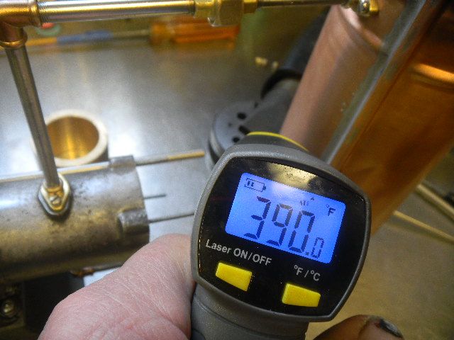
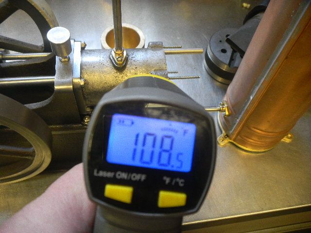
Next two pics show the temp at the nozzle of the heat gun and then the side of the cylinder just before I shut things down.

DSCN3027_zps1dc1b19d.jpg


DSCN3029_zps79fbe3fb.jpg


And yeah, I have a thing for thermometers.


While I had the two piece cylinder head off I decided to “casterize” it.
Casterize: (not a real word, I think) make machined parts look a little bit like castings. Simply put, this is brutalizing the part with a coarse wire wheel on the bench grinder.

DSCN3008_zpsbe413c4b.jpg


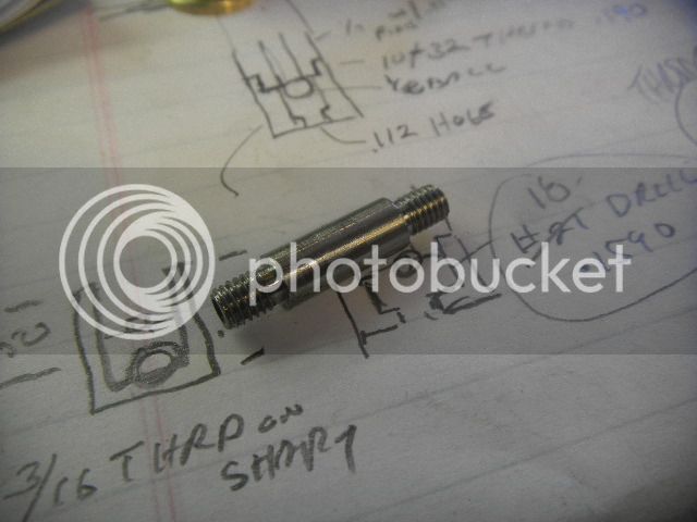
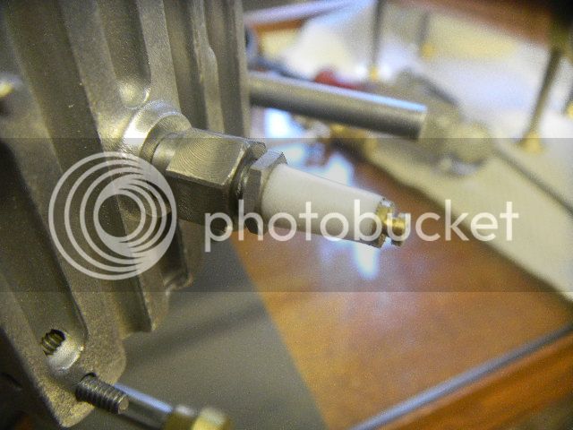
I also upgraded the spark plug from the ¼’-32 plug I had in there to a 1/16”NPT, two piece plug I made about six months ago.

DSCN3010_zpscac74c13.jpg


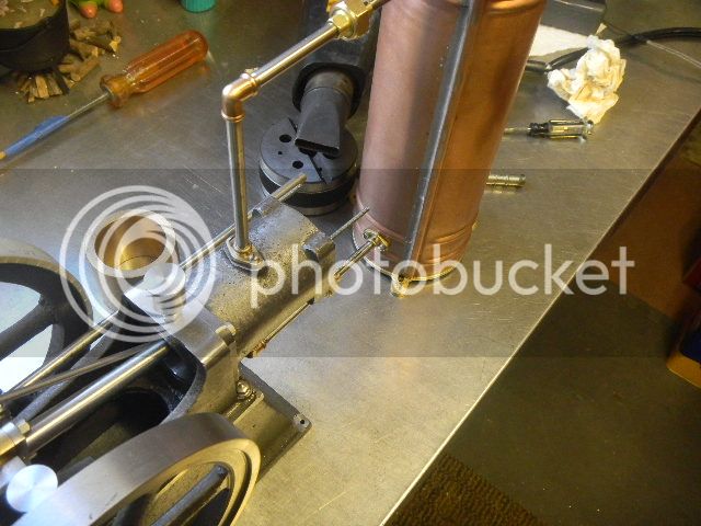
Now, with the cylinder head off and the side shaft cleared of cams, I can slide the magnet wheel on and get along with figuring out the placement of the hall sensor.

GUS

PS, Is it just me, or has the new version of Photobucket added a new layer of difficulty to adding pictures to our posts?
 
Good progress Gus. Can't wait to see it run.

Air bubbles will kill the thermosyphon effect for sure and if your tubing ID's are small it could be problematic. A drop or two of rubbing alcohol will help to eliminate the problem should it become irritating.

PS, Is it just me, or has the new version of Photobucket added a new layer of difficulty to adding pictures to our posts?
When PB ran out the beta tests of this upgrade I complained about that very same thing. Obviously they filed my suggestions in the circular file:rant:

Phil
 
Hi Gus

Great progress; the engine is coming along nicely.

I have the same complaints about Photobucket; instead of being able to get your (img) code all from one page you have open each picture:confused:.
I used Web Shots for years with out any problem; I switch to Photobucket and in less than 4 months they say I have exceeded my bandwidth and blocked the links to all my pictures. So I give them some money and only a few of my pictures will now load:mad:. They say that is is supposed to be automatic (as far as the links working properly again); I haven't had time to look into it.

Dave
 
If you listen careful and try not to laugh at the dumbass who got in the camera, YOU CAN HEAR IT.
I'M PROUD PAPA!!!!:D:D:D:eek::D:D:D


I got the solution for the hall sensor mount figured out. I put it back together this morning, set the valve timing, then the spark.

First forty spins, nothing!! It drew fuel up to the carb, but wouldn't fire, tried a lot of things.

Then pulled the spark plug and primed it.
Yeah, it started right up.

Did it again and, yeah, it runs but the carb doesn't want to work.

Couple more different fixes, no, won't even burp.:(

Removed carb and primed the intake port, yes, the engine RUNS, and pretty good until the prime goes away.

Am I happy??? Hell yeah!!!;D;Dwoohoo1woohoo1woohoo1*beer**beer**beer*
And starts easily when primed, the carb doesn't work.

Carb/fuel problems can be vexing, at best.
But, there is nothing more dissapointing than the deadly silence of an engine that doesn't run.
Been there, done that. Big time bummer!!

I'm elated and I think I'll have a couple more beers. *beer**beer*

It don't get much better than that!!!

GUS

Oh yeah, if you didn't understand the last sentence, "push rod for the intake valve".
I forgot to tighten the lock nut, when I set the timing.
 
Last edited:
Excellent job Gus...the details? You'll figure them out, but for now congratulationsThm:

Cheers,
Phil
 
Congrats Gus!!

Way to go; you will have the carby problems sorted out in no time.

Dave
 
Congrats Gus. I'm sure you will figure out the carb problem.

Vince
 

Latest posts

Back
Top