Hi Vince,
Making a second muffler was fun, having to make it was not.
Brain farts are way to common in my world.

Im about two weeks behind the actual build in my posts, catching up seems to be impossible so I wont even try. Ill just try to keep posting in the order I did things.
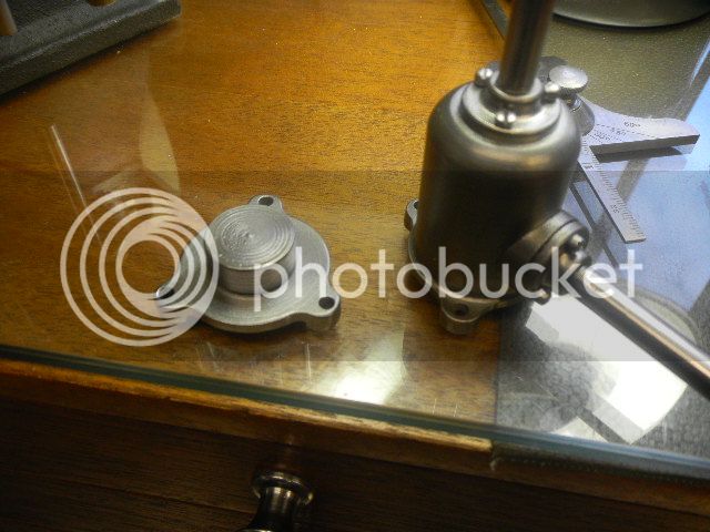
The lost metal order finally got here about then, meaning I could finally finish the carb.
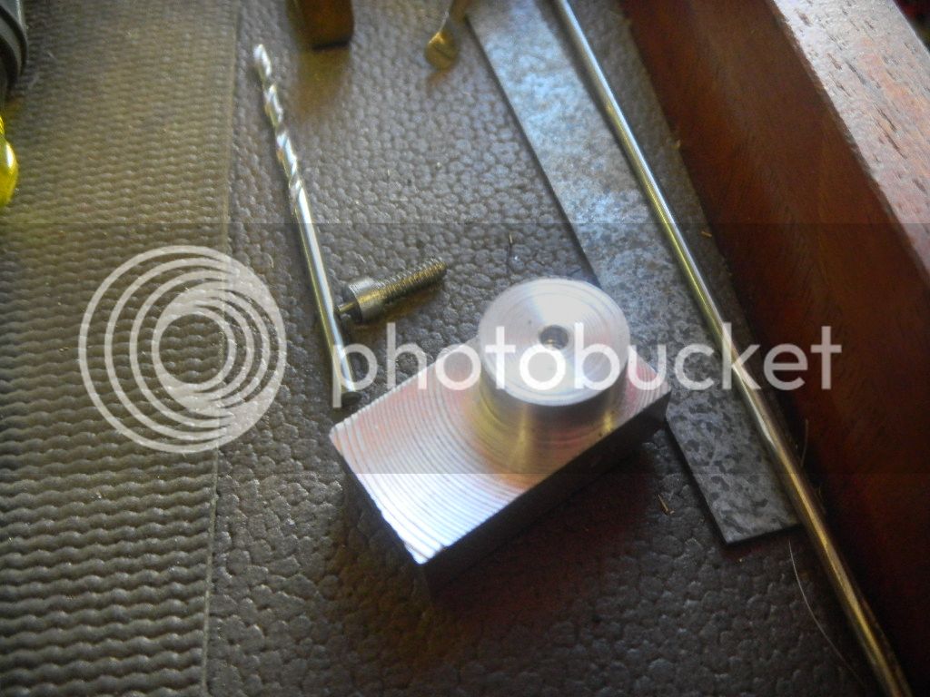
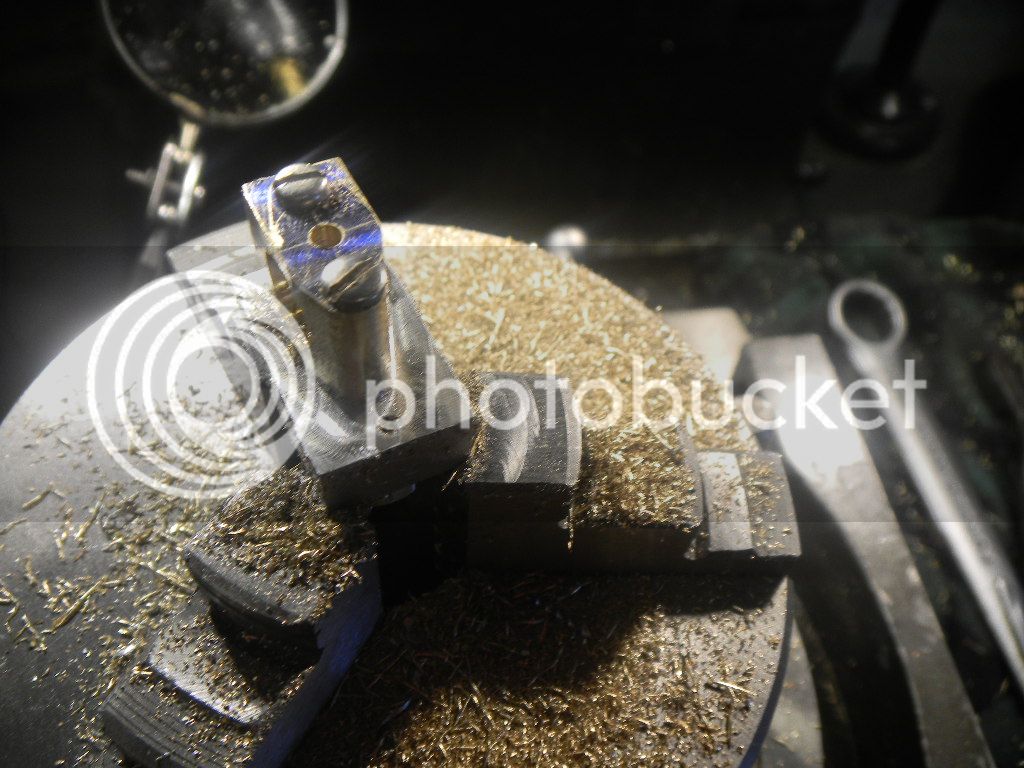
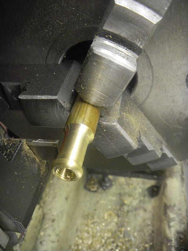
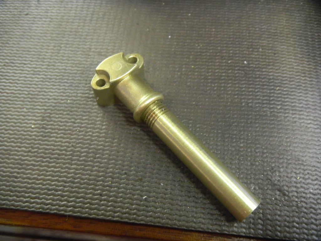
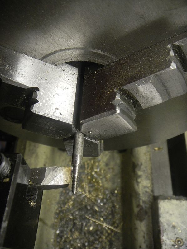
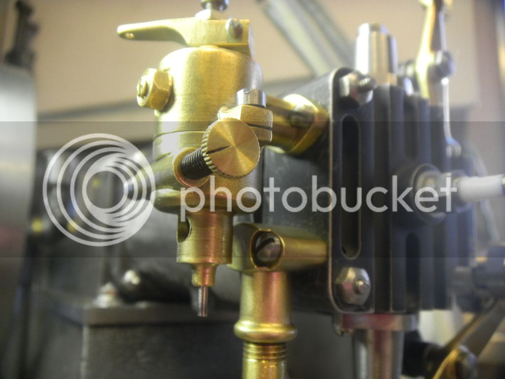
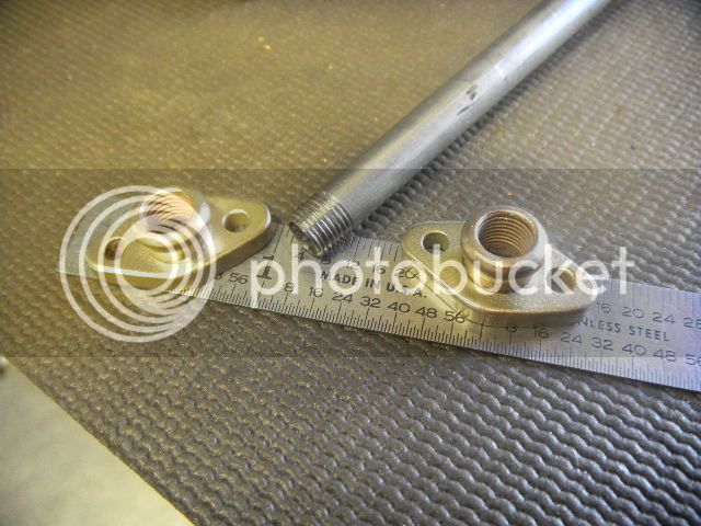
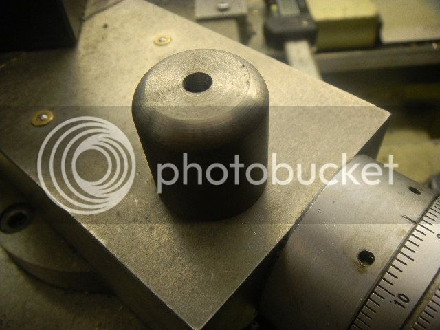
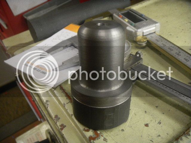
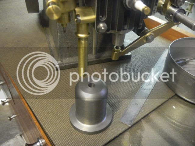
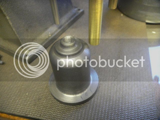
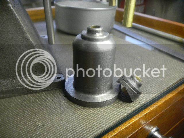
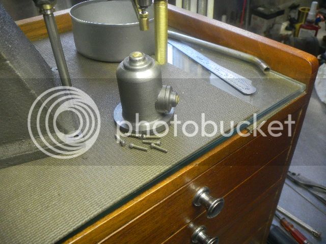
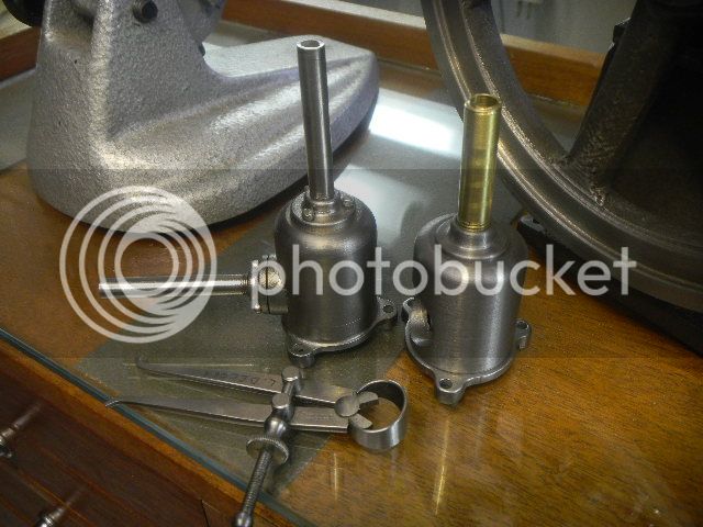
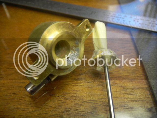
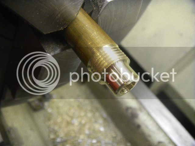
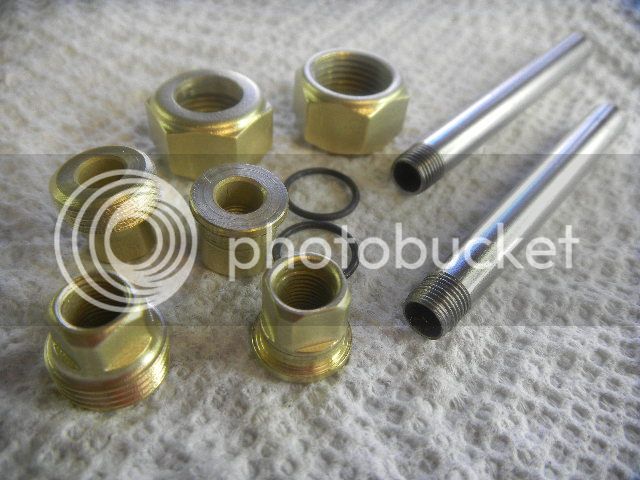
Not rocket science, the carb valve was made
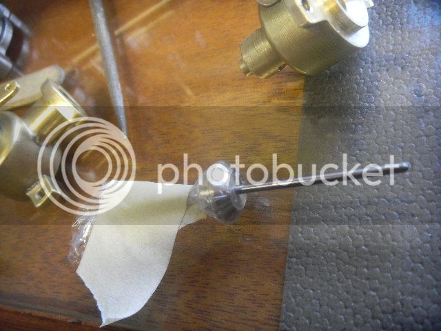
and the elusive 1/16 stem was Loctited in place, and cut to length.
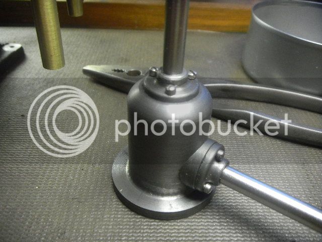
Valve finished, it took about a half hour after waiting weeks for the 1/16 rod for the stem.
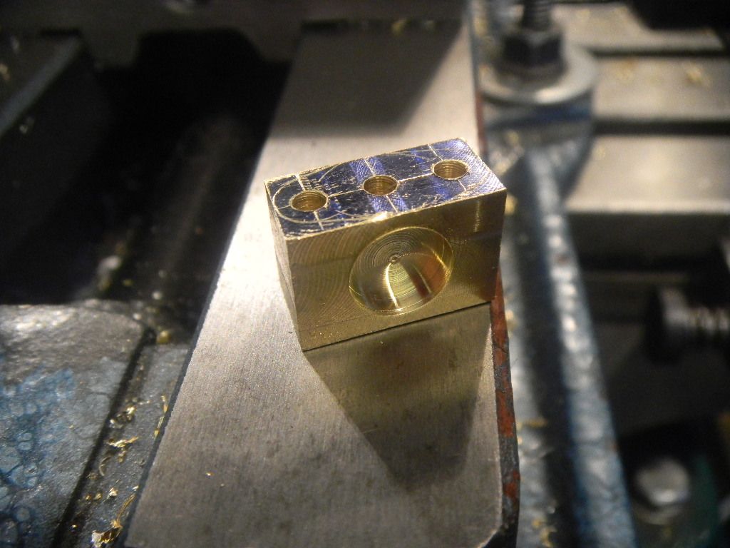
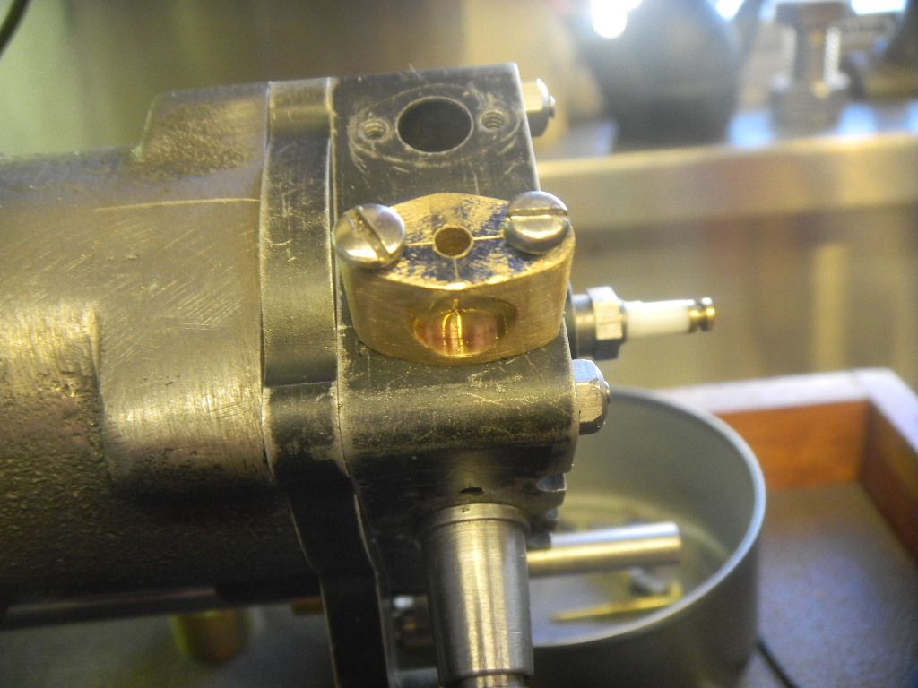
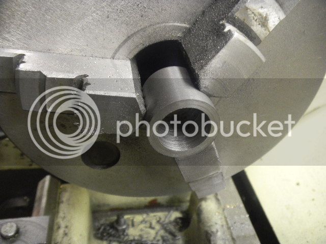
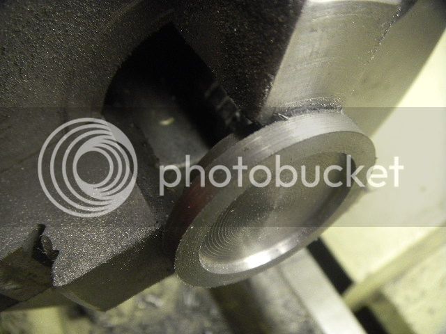
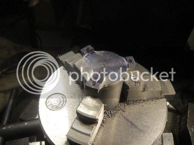
Now to repair the buggered up fuel inlet hole in the middle of the valve seat.
I chose to copy Mikes repair and try the JB weld method.
Not wanting to plug the fuel inlet hole or leave a big gob of JB to have to tediously lap flush, I decided to try to limit the amount I had to remove.
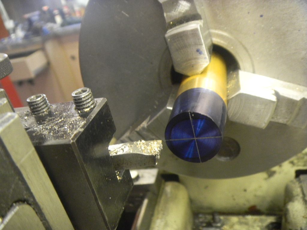
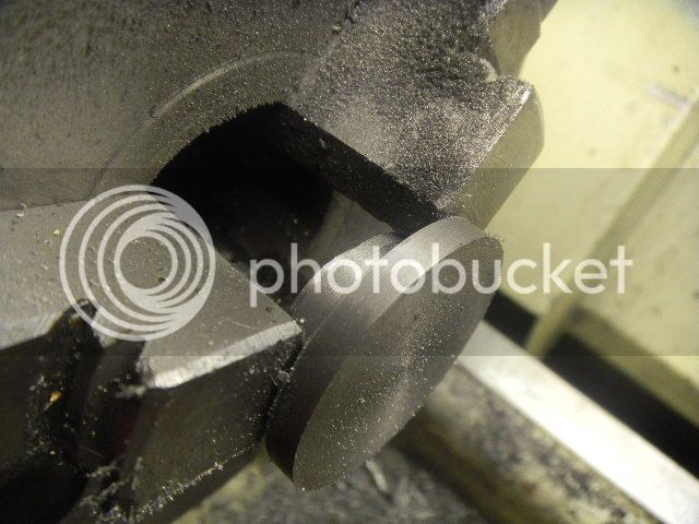
First was to wrap the valve face with plastic food wrap and stretch tight enough to remove as many wrinkles as possible.
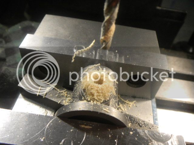
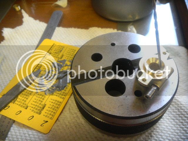
Then with a drill shank inserted in the hole the JB sparingly applied and the bit removed. This would help eliminate the possibility of stuffing the hole.
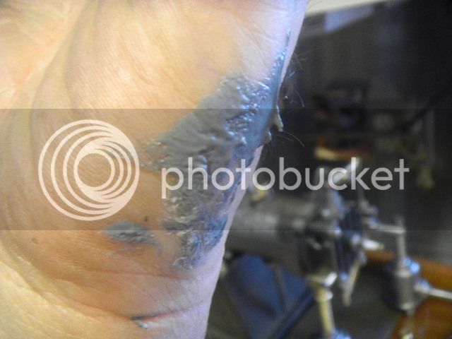
At this point I realized that the leftover JB mix should have been removed from the immediate work area.
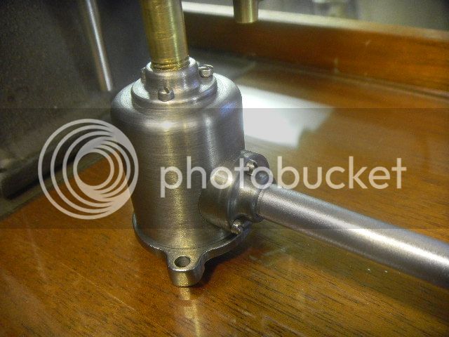
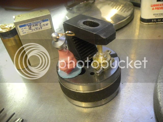
JB cleaned from hand, the valve was inserted in the carb body, weighted down to and left to set overnite.
It worked pretty well, but I probably could have gotten a the same or result by sooting the valve face to prevent sticking.
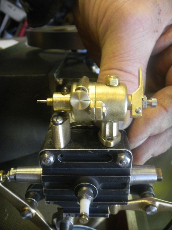
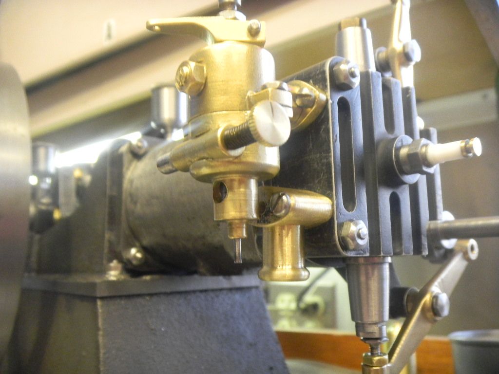
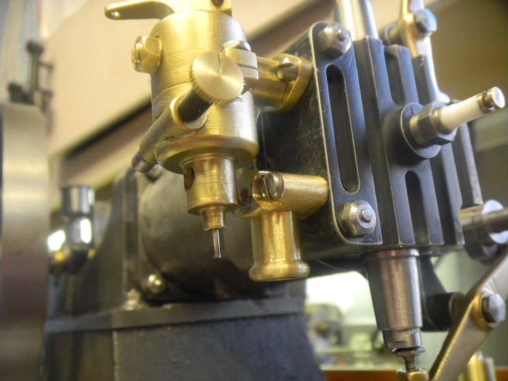
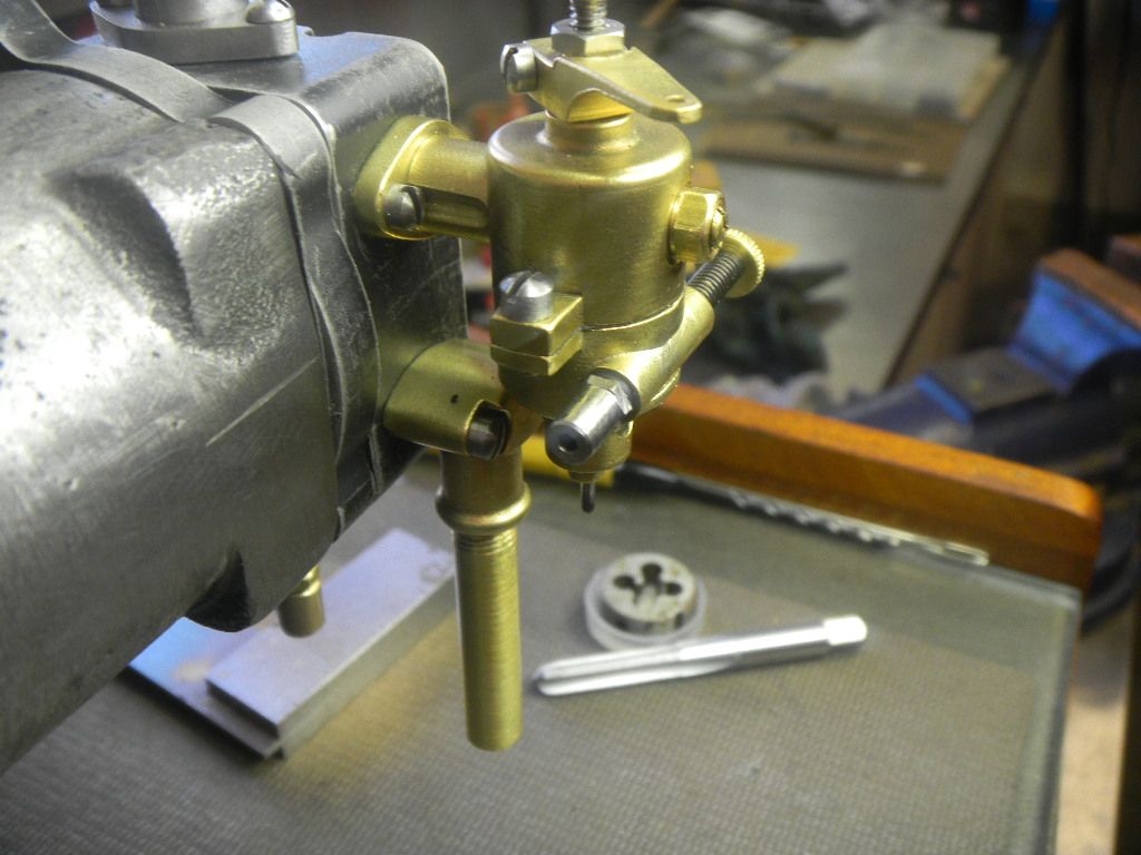
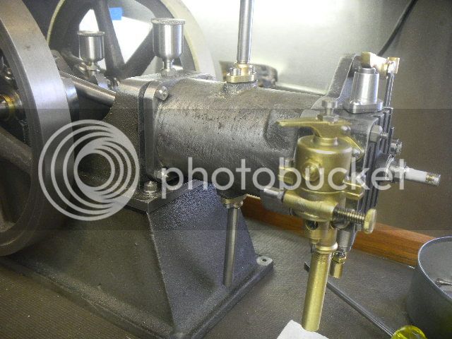
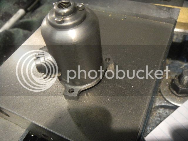
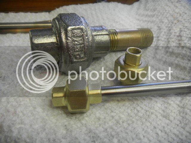
The seat lapped in really nice, the pic was blurry, but the carb got reassembled and installed on the engine.
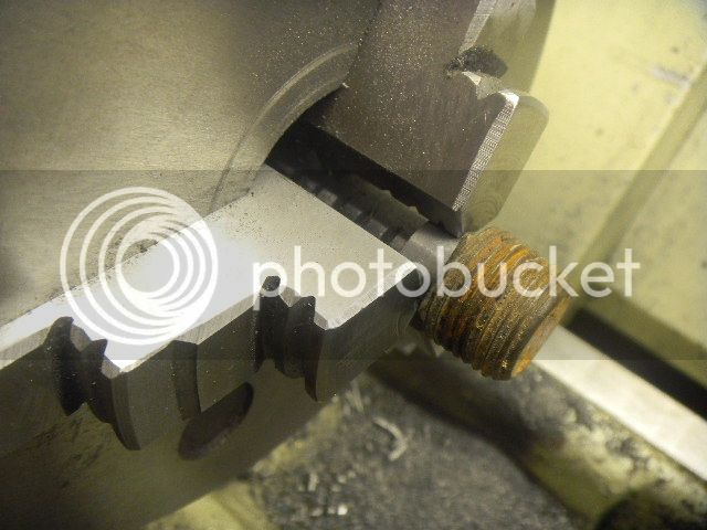
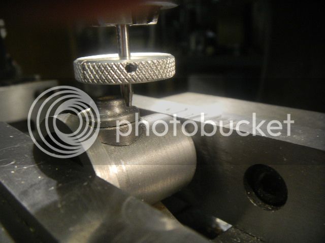
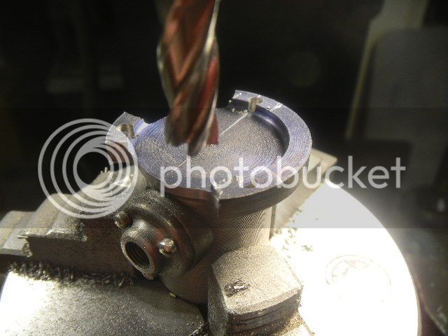
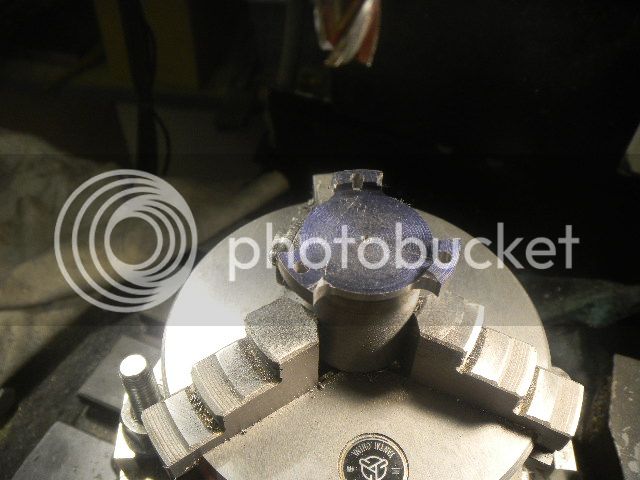
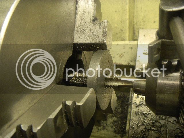
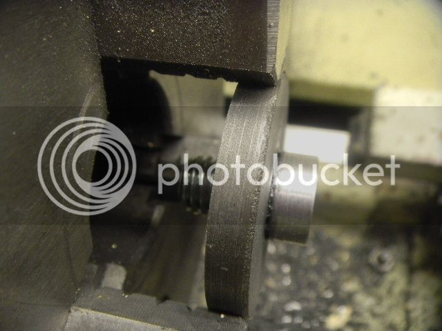
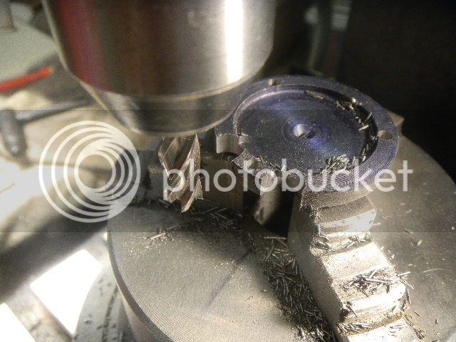
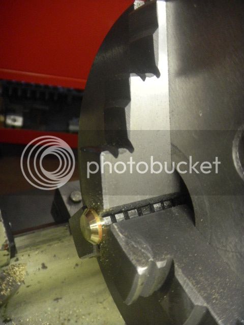
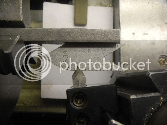
I guess I skipped ahead a little. I forgot the part about making A George Britnell valve seat cutter, not nearly as pretty as Georges but it did the trick.
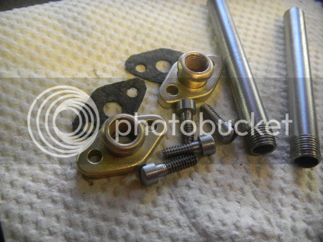
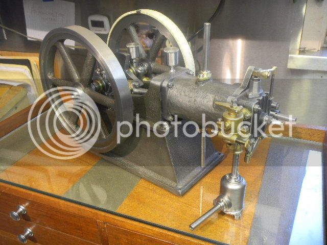
Valves lapped into the housings and installed in the head, head gaskets made (there are two) and installed, I wrapped the flyweel with masking tape and marked off and set the valve timing.
Ive finally got COMPRESSION.
Not just a little, the engine turns freely and bounces off the compression quite nicely. I think in that respect and if the carby works, Ill have no problems getting it running. I hope!
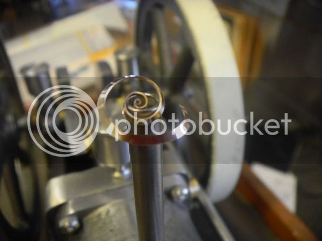
At any rate I can see the end of the carb valve stem lift on intake so that part is apparently working.
I'm not in a real hurry to get into the usually frustrating chore of getting the engine running and there are a few more accessories such as the cooling system and fuel tank to build.
A temporary fuel tank I have, but the cooling system will be important as I feel that this engine, not being hit and miss, will heat very quickly.
I might as well make a permanent solution, which will be a cooling tank.