Wyvernish Build

Home Model Engine Machinist Forum

Help Support Home Model Engine Machinist Forum:

This site may earn a commission from merchant affiliate links, including eBay, Amazon, and others.
Gus,

In the nicest possible meaning.

You are mad but bl**dy brilliant!!
Just "watch" it with your wife!! (Come on now Gus, she will miss it. Do you really believe not)?

Such a great build, write up and soo funny but also entertaining and a good way of learning, thank you mate!!

(By the way, this is my third look through from the beginning of your build to get some ideas and oh boy, have I learnt a lot. Again thank's).


Many kind regards,

Ron.
 
Last edited:
Awesome, I think you will need to add a plaque on completion dedicated to the Mad Hatter from Wyvernish!
 
Wow, I knew was treading in some uncharted territory when I started making the ignition tower and I wasn't sure what to expect when I added the watch face and then the dummy terminal in the top.

Thought maybe I'd get booed off of the stage.

You guys have me blushing, Thanks.

I like to mess with people's minds a little, it stirs the imagination.
The story will me that it is a magneto and the numbered dial adjusts the timing, the numbers indicating degrees BTC.
Almost believable, almost. Not sure I can say that and keep a staight face.:D

Too bad I have to unhook the jumper in order to run it.
I was going to experiment a bit, I didn't know if energizing the tower would monkey up the Hall sensor, but my idea was dashed when I realized that the spark would just arc to the sideshaft. Not enough room inside for the plug wire.

GUS
 
Last edited:
Back to the issue at hand, get the Wyvern running right.

Somehow I figured it would spring to life and settle in to a smooth running engine.
Far from the truth.
I had to choke it to get it to start, and got it too smooth out at a reasonably slow RPM, but, inevitably, it would stall.
Looking for a solution, I came up with a few fixes.
Number one on the list, and easiest, add a grounding electrode on the spark plug.
My little H. Ford ran like a champ after I went that direction.
Some engines don’t seem to need one.
Disassembled, I drilled the rim .046 and added a bent SS wire. No problem, it went smooth as silk.


DSCN3126_zpsfe97f284.jpg


I ran the 1/16” NPT die back over the treads to make sure I got any excess solder cleaned up.
Life is good, clear sailing, I thought!!

As I reinstalled the plug, near the end of it’s travel, I felt a little resistance. Thinking there was a little solder on the threads, I continued tightening to the final turn where there was another little resistance.

Hind sight is 20/20, I should have backed up and removed the plug, instead, I primed the engine, flipped the ignition switch and gave the flywheel a spin.
I felt what I thought was an early timing bump and spun the flywheel again. No compression.:(

Quick investigation, the exhaust valve was stuck open.
On removal of the spark plug, the valve closed and with my finger on the plug hole there “seemed” to be good compression. Close call. I thought I had ample clearance for the added electrode. The .025 gap on the plug was now 0.

DSCN3129_zps36aaa54a.jpg


Now to figure out what to do about the spark plug, it was becoming apparent that switching to a pipe thread plug wasn’t such a good idea.
I could have cut the electrode off and continued spinning the flywheel with the same result, but I was still thinking that adding the electrode would be a good idea, and it would be the easiest of the fixes to try.
 
I could pull the cylinder head plug up the old hole and re-tap it for the ¼” plug I had in it.
But I wanted to get the engine running. Maybe if I shortened up the thread on the plug and put another electrode on. There was a mark on the old electrode where it hit the valve, so I decided to shorten it up a little more than that. The tapered thread wouldn’t miss a thread or two.
I milled the end of the plug down and started drilling the new hole for the electrode and broke the drill bit. Now stuck in in the hole I had to try to get the piece out.

About then I started to feel like nothing at all I did that day (Saturday) was working out.
Maybe the gnomes were messing with me or maybe the nightshift thing was stealing my mind. I just spent about a week of shop time messing around with a nonsense fantasy. (but it was a lot of fun:D)

At any rate, I managed to get the broken bit out of the hole. Fortunately I have spares for most of my number bits so I finished drilling and soldered another electrode to the plug.
Unfortunately the last little bit of turn in and it was just bumping the valve again.
I backed it out a bit and tried to start the engine but the compression was just not there.

Maybe the valve is bent.:eek:
I have to tear it down and see what’s going on. RATS!!!!:mad::wall::wall:

GUS:(
 
Gus--I know where your heads at. I go there just about every time I build an i.c. engine. In fact I'm sure most of the i.c. guys will tell you----building i.c. engines is fun---But it makes ya Crazy!!!!
 
It always seems to be the last few details that drive you nuts :(

Stick with it though, Gus!
 
Brian, well put.
Maybe we can start a support group.


Sunday(St Patti’s Day)
I removed the engine from it’s temp. base, so I could work on it.
First I pulled the exhaust valve cage and took a looksee.
Aside from the normal black WD40 residue, the outward appearance was OK.
Same for the intake, but cleaner.

I pulled the valves from the housings and wiped them down a bit.
I was a little surprised that the exhaust valve was now black from the head up to the port.
Almost like I blued it.

DSCN3139_zpsd3c08abc.jpg


Not seeing any sign of damage to either, I decided that lapping both valves again couldn’t hurt.

DSCN3140_zps64c532e3.jpg


What next?
Pull the cylinder head and take a look inside was my choice.
Right off, this was blatantly apparent.

DSCN3141_zpsa3fecf76.jpg


Blown head gasket, or I should say eroded, maybe.

DSCN3154_zpsfcb7bdb1.jpg


I can’t say this was the problem earlier on, but it is now.
I went to see what the outer head gasket looked like and found it had vulcanized itself to the other side of the inner head.

DSCN3144_zps4a6101ec.jpg


Add to this the black exhaust valve and you don’t need an instruction book to realize, that this head got really hot.

I have no idea what the composition if the gasket material is, some rubber content I’m now thinking. I bought a 36” diameter disc of this material (valve gasket cutout, big valve at that) at an engine show flea market, maybe 10 years ago. At .025 thick it is has been a treasure, and it’s almost all used up, save for all of the small cutoffs I’ve saved.

This is the first problem I’ve encountered with it. I used it for the head gasket in my Lil’ Brother and it is doing that job well.

Kind of interesting, that the side of the blown gasket against the evidently cooler cast iron was unharmed and the outer gasket was only stuck to the inner head piece. The inner head must have gotten really hot. Maybe a design flaw on my part. It is fairly thin and has a conical hole leading to the outer head.

Even when I was first running the engine I was surprised at how hot the head got.
I’m thinking too lean fuel mixture and or late timing.
Here are a couple shots of the inner side of the head, a little crowed I would say.

DSCN3145_zpsc0ca1ff6.jpg


DSCN3148_zps069b385c.jpg


I have to search thru my gasket materials and see what options I’ve got.
I did an improvised cylinder leak down test. With my palm over the hole and the piston pulled to BDC, it took just over two minutes to release me.

DSCN3151_zps9abdc783.jpg


DSCN3152_zpsa12b6df4.jpg


I don’t think the O-rings are the culprit.
More to follow.
GUS

PS, I'm starting to get used to the new Photobucket, not so bad once you play with it for a while.
 
Gus, Could the gasket be the cause of the over heated head, my thinking is that a finned head acts like a heat sink, and maybe your gasket is acting like a insulator and stopping full heat dissipation through the head, just a bit of food for thought.

Mike.
 
Hi Gus. I was thinking that a very thin metal shim gasket might do the job, but I was also thinking that a lapped mating face and no gasket would be OK.

The cylinder head on my Wyvern has no gasket just a thin smear of Hylomar gasket sealer, my cylinder head is a one piece casting as supplied with the castings kit, the head does get warm but not enough to cause concern.

I'm sure you will crack the problem.
Mike.
 
Yeah Mike, exactly what I'm thinking. The gaskets are blocking heat transfer.

I'm not sure my cylinder head has enough cooling fins and things are definetly pointing to the "extra" part of the cyl. head as the real culprit.

I started my thinking toward cutting a cooling channel in at least the inner part, also in consideration is o-ring seal on both pieces.
Kind of iffy, the o-ring thought would not readily support cooling passages into the head.

I'm hoping and still thinking that solving the mixture/timing issue before further mods, might solve the problem.

All suggestions more than welcome.

Seems this project is not done yet, and I'm not real dissapointed.

Mike, thanks for your input.

GUS
 
Last edited:
I haven’t had much free time to play and progress to get the Wyvern running right has slowed, almost to a halt.:(
I’m thinking O-ring or maybe the Hylomar sealant would be the best solution to the hot head. But I’m hesitating to put the cylinder head under the knife to cut a groove for an O-ring. And I don’t think I’ve ever seen Hylomar on the shelf
Although I think I’m wasting my time with head gaskets, I decided to take another shot at it, this time with a different gasket material.
I had two types of gasket to try, both have graphite in them.
 
One type has metal sandwiched in, pretty much looks like a hi temp gasket material.
I tried my had at cutting a new gasket out but the material of the outer sandwich is kind of brittle and breaks away from the core metal too easily. This stuff would probably be better for larger gaskets.
The other choice is thinner and more flexible and cutable but has a textured finish that seems to rough for small applications, but maybe it will have some crush to it.
I had my doubts but went on to make the two gaskets I need.
A quick test with bubble solution showed seepage under compression, but the compression seems good.
The gaskets are already installed and I don’t have much to lose by trying them.

But as long as I have the cyl head and cams removed, first I’m going to correct the off center problem with the cams.
All along I’ve been having an off center experience almost every time I use my RT. The cams were no different.
At any rate I’m going to plug the shaft holes in the cams, center up on the round part of the cam profile and redo the holes.
This will at least get the valves open to their intended height as I won’t have to leave excessive rocker clearance due to the off center.
 
HI Gus, Maybe Hylomar is only available here in the UK, I hope your new gasket is a success, have you given any thought to using a PTFE ( Teflon ) sealer or the tape to form a seal, I have used the PTEF plumbers tape to seal steam covers on my steam engine.

I used the tape to seal the flange on the Wyvern's intake flange.

Mike.
 
Mike, thanks for your suggestions.
Quick note on the Hylomar, there is a distributor in the US.
http://www.hylomarsealant.com/_resources/_html/products.html

I was going to order some if the the new gaskets didn't work.
But they did, and the engine is back to running and a lot better than it did.:)
I had a sustained run going for 2 or 3 minutes before I shut it down, I didn't have any water in it.
It wasn't running 100 percent though.
It wants to run rich and any attempt to lean it out more always ends up with it stalling.
Could be the needle valve messing things up.
Remembering back when I drilled the jet, I used a #65 bit as I my cheapy small size bit set wasn't up to par for the #70 called for. I just kept rying the next larger bit until I got to one that would cut the 303SS, which isn't really tough stuff to machine. A new, better, set is in order.

Real good news is I didn't burn my finger when I felt the cylinder head.

Another reason I shut it down was one of the main bearings was spinning.

I pinned both mains which I forgot to do, and sanded the mating surface of the cap a bit to tighten the fit.

My real work has become an almost unacceptable amount, a new store build and I've become backed up with the restaurant maintanance and working nights on weekends to catch up.
Almost too much for an old guy like me and really cutting in on my fun time.:( I'm supposed to be semi-retired.
I'm only home today because my poor aging (89) mom ended up in the hospital.
Thankfully, she'll be OK.

When I get home from visiting today, I'll get back to the Wyvern for a bit, but my hopes to get things staightened out before Cabin Fever may be in jeopardy, it's coming up quickly.
But, if even if I don't get it straightened out, I'm taking it with me as a work in progress .
IMHO I think it's pretty neat to look at, it makes me smile.;)
 
Last edited:
Hi Gus.
Good to hear the Wyvern is up and running again, it looks like just a bit of fine tuning is needed and you will have a reliable engine, as you say the Wyvern is a nice looking engine.
Hope your Mom gets well soon.

Mike.
 
Hi Gus,
I hope your mom is on the mend.

See you at Cabin Fever.

Cheers,
Phil
 
Well, the Cabin Fever Expo for this year is now history, had a great time, met some more of the members, saw a lot of really nice works of art, bought a few things, also talked with others until my voice got weak, just a great time.

As well as the three days I set aside for the show, I also got a break from work for a bit, which means I got some time to survey the damage. Not real damage, just the “my shop seems to have exploded” type of damage.
I spent a couple of days putting things away, contemplated what the next step for the Wyvern would be and the needle valve issue seems to be the first on the list.

I saw only one Wyvern at Cabin Fever, a good running “work in progress”. Nicely built and the man who built it made an unusual modification to the cylinder head.
He made an automatic air start system for it which entailed a completely ground up redo of the head.
I chatted with him for a bit and asked him what size jet he was using in the carb, I was surprised to hear he used a No. 75 drill in lieu of the No 70 specified, but the engine was running perfect, couldn’t argue that.

Back in the shop, I took a look at my shiny new set of tiny drills, that No 75 was scary small, and after a bit of thought I decided that a 72 was nearly in the middle and that would be my new jet size.

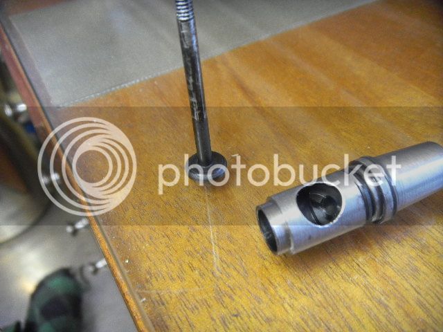
Starting with a 3/16 brass hex bar (Expo purchase, two assortments 1/8 to ½, one brass and on SS).
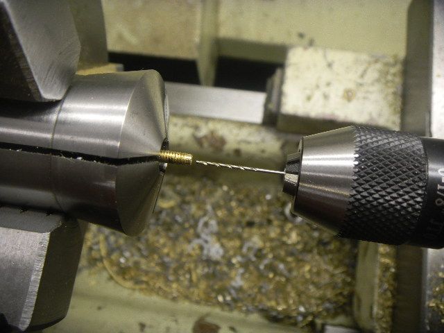
In the lathe drilled part way through 3/64” then rounded outside for the fuel hose and parted off, then flipped around and bumped with a spot drill and got ready to drill the chosen no. 72.

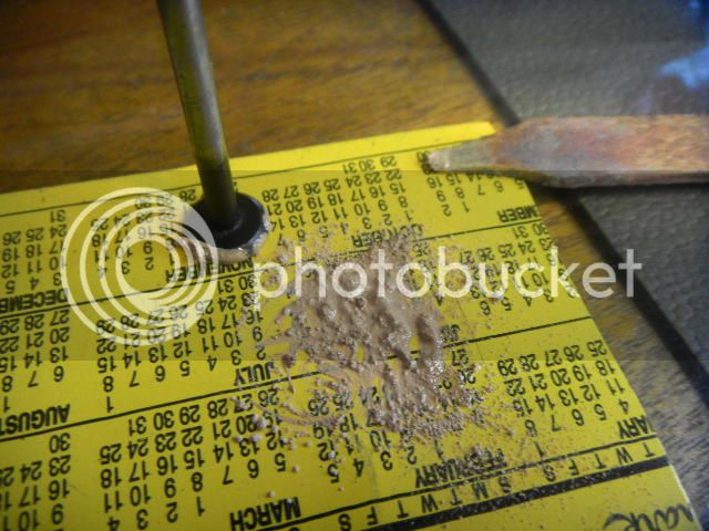
New weapon is another Expo buy (Little Machine Shop, show special, 10 percent off catalogue), precision driller, had to have it.
In the tailstock chuck and with the old Grizz turning at warp speed, I had no trouble at all pecking the bit through, should have bought one of these a while ago.


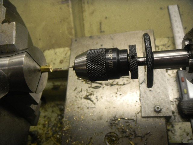
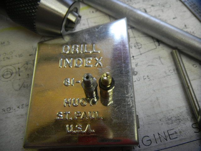
The outside was reduced and threaded 4-40, that part done. An almost amazing hole size difference.


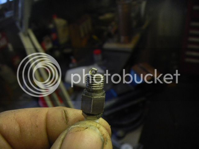
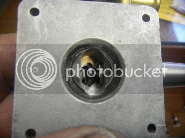
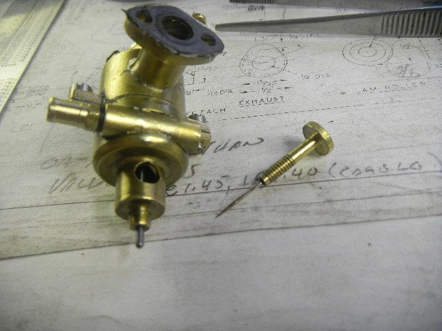
Now to modify the old needle, which meant to cut off the machined point and drill the end to fit a No. 5 ? sewing needle. Somehow I can’t remember off hand if it was a 4 or 5.
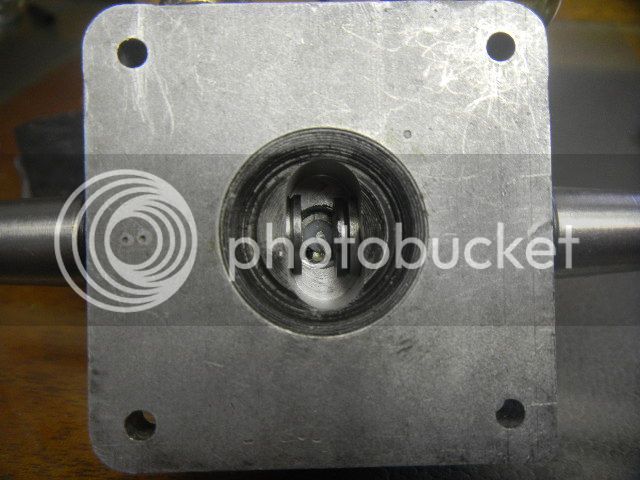
With the head precariously grabbed in a 5C collet in the three jaw the hole was drilled the length of the drill flutes.


The needle was then cut to length and Loctited in place.


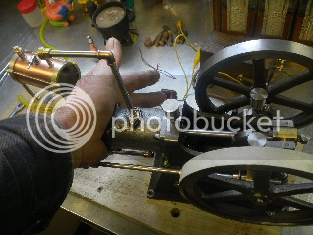
Put back on the engine, it started readily and, with a little adjustment, got the engine running reasonably slow.
I shut it down and added water in the cooling tank and restarted it. It sounded like the timing was a tad late but I just let it run,. After a couple minutes it started slowing down and running rough and in a short time just quit.
Now what? It was turning freely and not real hot, so that wasn’t the problem.
OK, check the timing, yes in runable range. I say runable because it’s a bit difficult, for me at least, to turn the flywheel and listen for the tiny spark. At any rate runable range, to be fine tuned by trial and error when I get it RUNNING RIGHT.

I’m in the frustrating stage of engine building, working the bugs out.
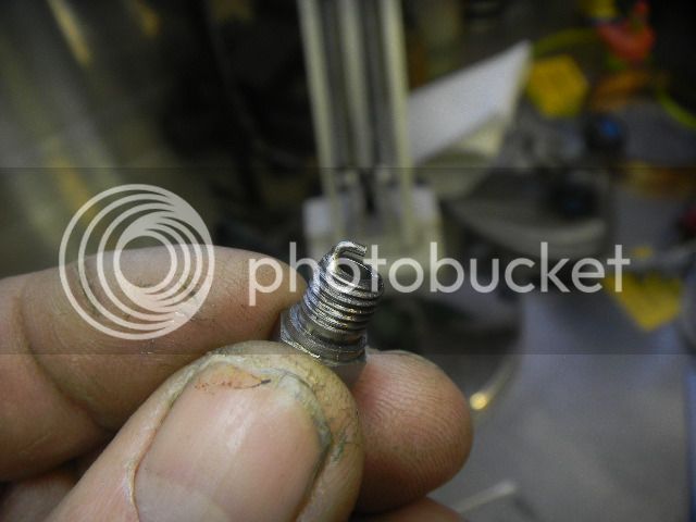
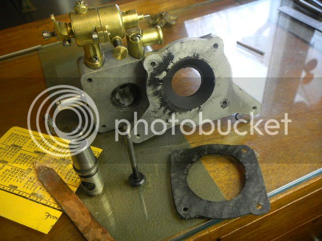
The latest bug was the threaded keeper on the exhaust valve worked loose.
I didn’t like that detail when I was building it and when I saw Mike’s engine I was sorry I did the that way.

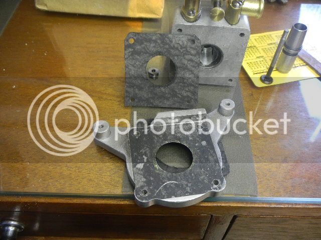
I’m going to, pretty much, take things apart and redo some sore spots.
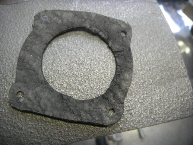
One of which will be to O-ring the head, and I’ll deal with the threaded keepers at that time. Deal with will probably only be to Loctite them to the shafts.

Another will be to make tapered bushings for the flywheels.
I somehow got the holes too large. They seemed a good fit early on, but as the build progressed they loosened up, maybe from me spinning them on the shaft, which I did a lot.

When I would tap the tapered key in place it was tipping the flywheel slightly causing a wobble.

Question: Should the keyway in the flywheel have been broached at an
angle to match the key??

The cam shaft side ended up with a piece of .001 shim all around to keep it from wobbling. Although I think the amateur builder was probably the main cause.

More adventures to follow.

GUS
 
Last edited:
Back
Top