Wyvernish Build

Home Model Engine Machinist Forum

Help Support Home Model Engine Machinist Forum:

This site may earn a commission from merchant affiliate links, including eBay, Amazon, and others.
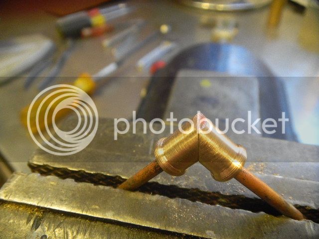
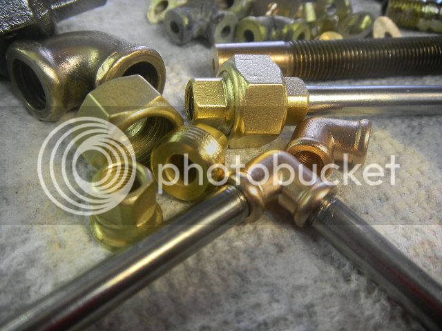
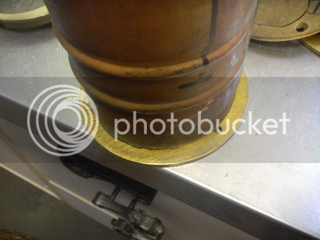
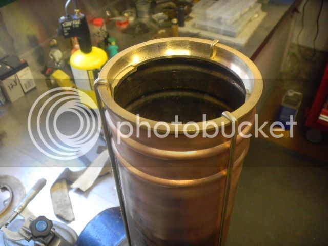
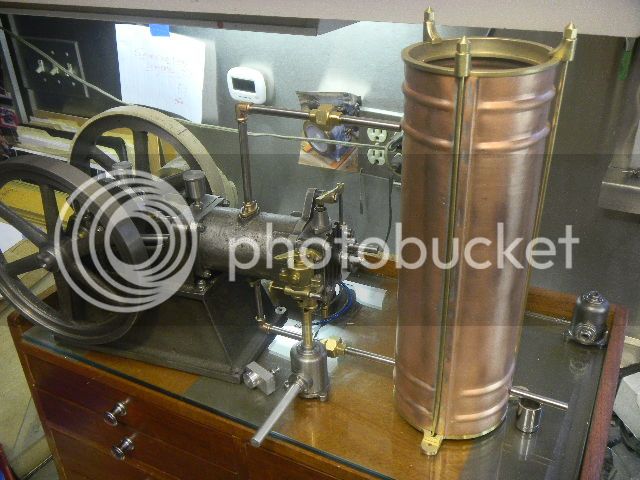
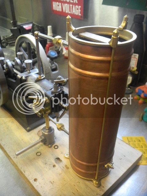
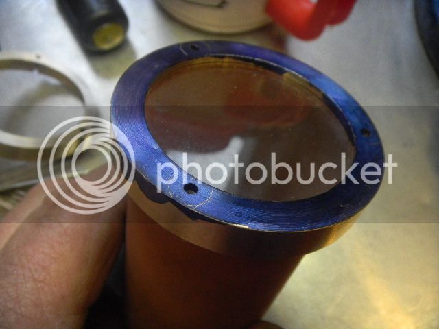
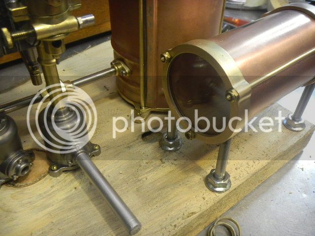
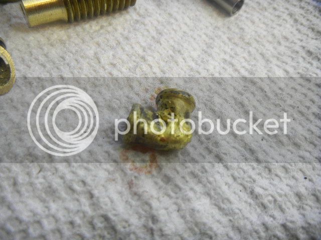
Since I already have the exhaust and water outlets made with a rounded rim on the tube part, I wanted to keep with that theme, so the elbow I dug out of the fitting bins would be the model.
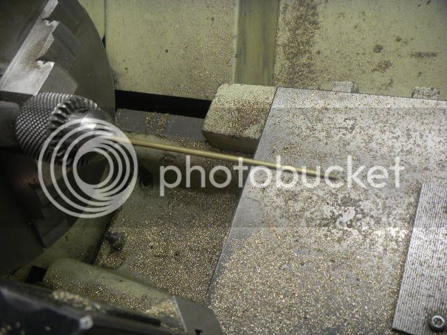
First thing was to make a small rounding tool out of a water hardening drill rod.
Simple enough.

DSCN2856_zps763fe06e.jpg


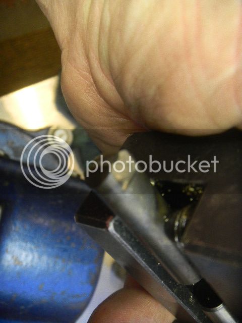
I was only cutting brass but I figured I might as well harden it.
Quote: "I new better but did it anyway."
First lesson learned that day was not to use the dogs Styrofoam water dish for cooling a red hot piece of steel.

DSCN2855_zps0baa2053.jpg


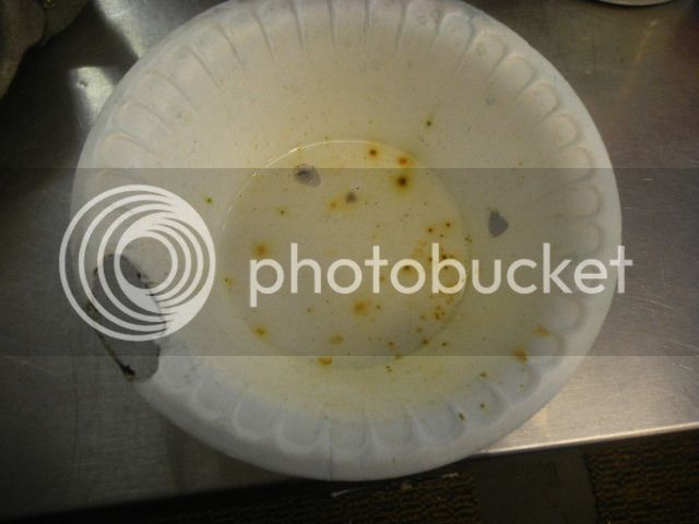
The rim was burned with the torch when I pulled it off of the workbench because the water was running all over my welder.

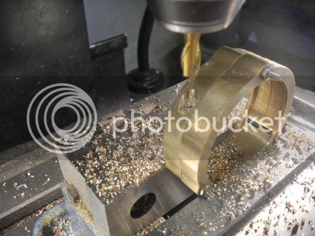
That lesson duly noted I got busy making the half elbow pieces.
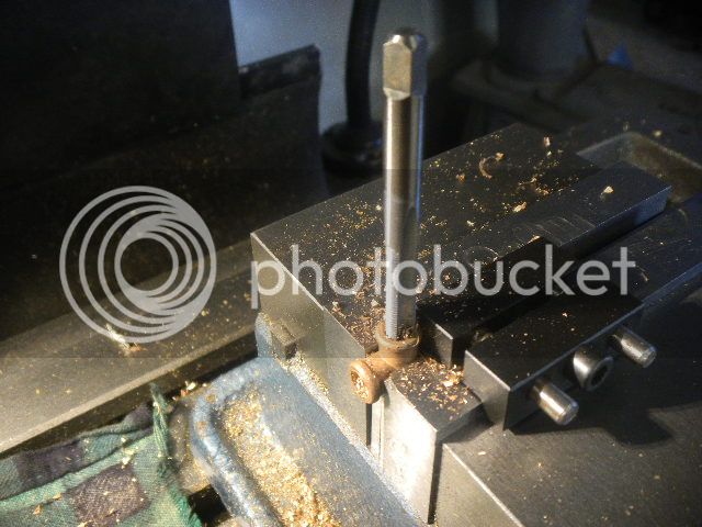
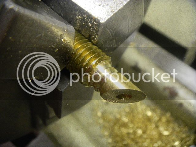
I first tried making the rim then turning the minor diameter and drilling a pilot hole.
Poor plan, it would be difficult be difficult to hold while cutting the miter, which I intended to do with an end mill.

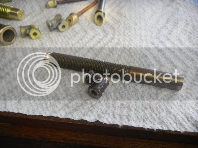
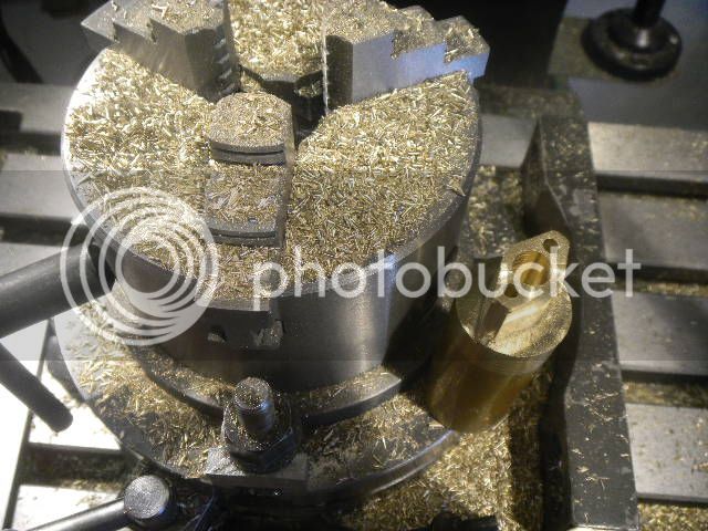
After figuring that out I decided to make another rim farther down the same piece which was a piece of brass bolt. That ended unhappily. Holding a work piece by the threads is something I should do less often or not at all.

DSCN2857_zpsae76ebad.jpg


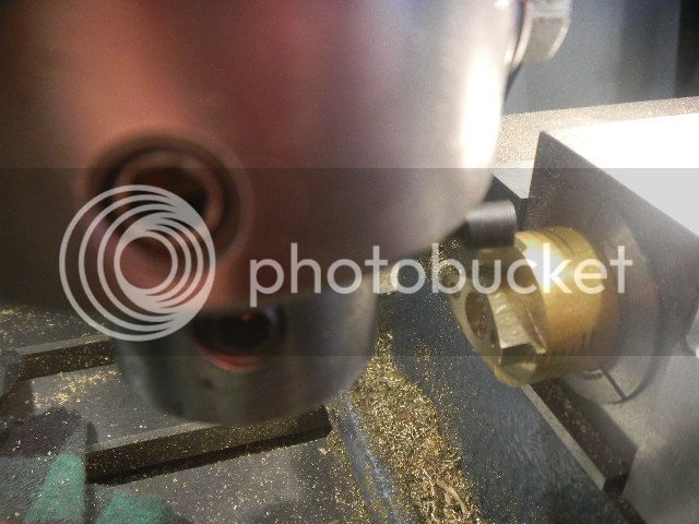
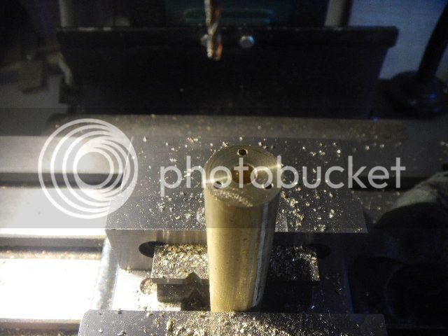
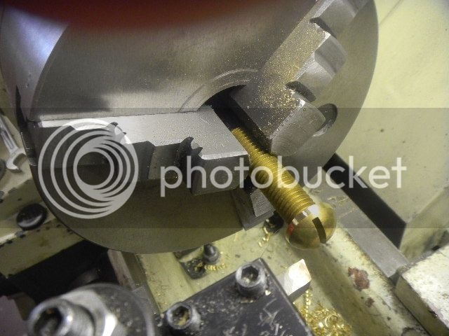
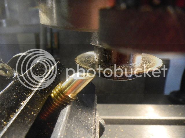
New plan. Drill the pilot hole, turn the small end , cut the miter with the slitting saw. (Note: In an earlier post I was complaining about the screw on thearbor being siezed. While doing this cutoff, a bit of chatter loosened it up, maybe I won't can it after all.)
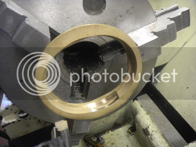
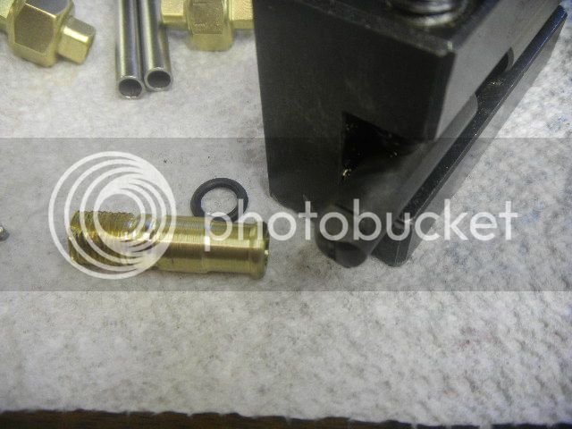
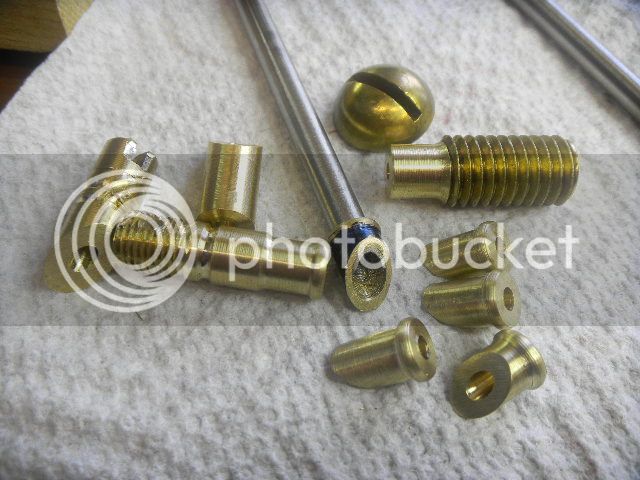
Then back in the lathe to make the rim and part it off.

For this and being the frugal person I am and not having a piece of 3/8” brass rod on hand, I sacrificed a couple of ½” brass screws that I have a few dozen of for quite a while and haven’t ever used one.

DSCN2862_zps0efd4e27.jpg


DSCN2863_zps9cbe0980.jpg


DSCN2864_zps0b4ac721.jpg


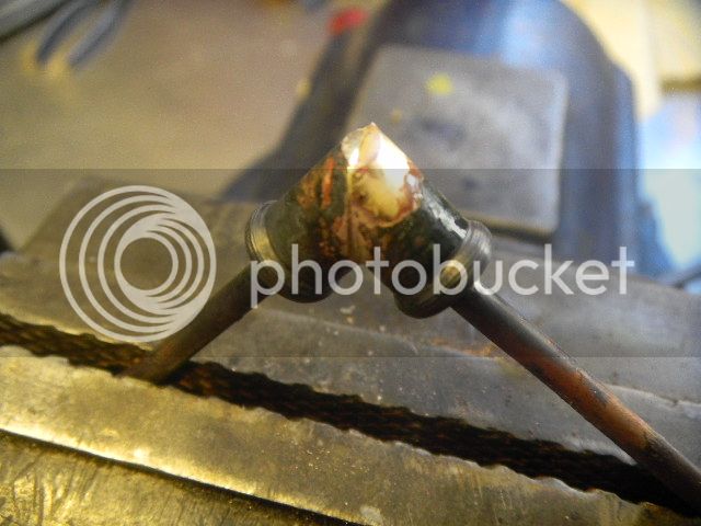
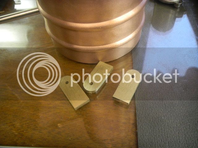
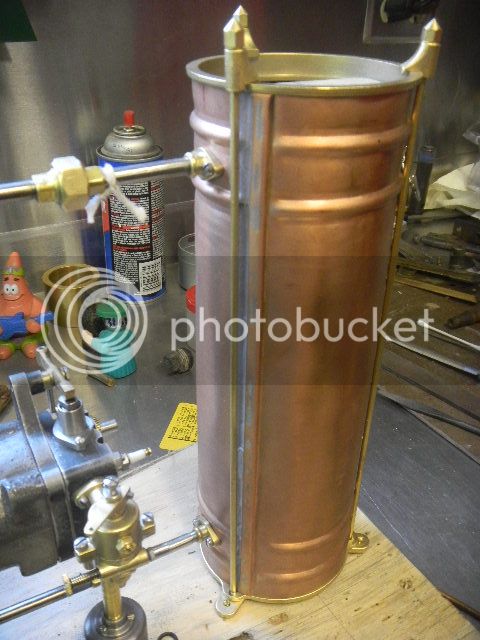
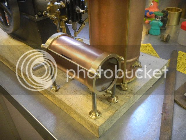
For times later I had this, ready for the torch.

DSCN2868_zps2b9d79d9.jpg
 
Both pieces ruined (more for the jar), I melted them.

DSCN2869_zps6f2e809a.jpg

 
Thinking maybe the screw I used may have a lower melting temp. than “other” brass, I got out my newly acquired Machinist Handbook, and found a page on alloys of copper.
Most of the yellow brasses had about the same melting point, so that was probably not the problem, but the thought was nagging me.

Digging thru a drawer full of salvaged small parts, I found a piece of what looked a red brass partially threaded rod, so I prceeded to make the replacements four more times.

While remaking the parts, a new thought came. Maybe the miters were a bit open on one side and that prevented the solder from flowing properly.

I devised a different plan, a bit sturdier than the fussy alligator clip thingy.
(Note: I prefer to devise a plan rather than develop one, less brain work.:rolleyes:)

DSCN2875_zpsae52cfb2.jpg


I also filed a flat spot on top to act as a landing pad for the solder.
 
Success.:)

DSCN2877_zpsa85b7611.jpg


DSCN2878_zpsa6150e37.jpg


It took some twisting to get the copper tubing out, which was caused only by the baked flux, most likely because I didn't clean the copper tubing.

Cleaned up some, then to the mill for drilling and tapping.

DSCN2880_zps4fe3f9af.jpg


Finished product and botched pieces plus cutoffs.

DSCN2887_zps69428578.jpg


Now where can I find a cooling tank?:confused:

DSCN2892_zps0f2f3ad6.jpg


Next day I found out PM Research makes a tree of fittings in the size I was using, easier, but...


Last edited:
Hey Gus,

The fittings all look great; tedious work but it will all be worth it in the end.

I'm thinking I may take the easy way and use fittings form PM Research.

I curious to see how you approach the cooling system, thermo-siphon or maybe an engine driven circulation pump?

Dave
 
Hi Vince,
Thanks, making the fittings was way easier than drilling out the SS rod for the pipe.:(
Just kidding.:D
Actually, I ordered a thick walled pipe by accident, only 1/8" ID and I did drill it out and it wasn't a lot of fun.

Dave, funny you should ask that.
Yesterday (real time) I took a 2 hr. drive on bad roads (blizzard of the century, 6" here) to the Rough and Tumble winter get together, had a nice time, but one fellow told me that the thermo siphon, which is where I'm headed, won't work, at least on an engine he tried it on. But he couldn't tell me why.
I think it will, unless the mini physics thing that sometimes effects things has someting to do with it.
If it doesn't work there's room on the side shaft to drive a little pump.

My experience with thermo syphon has been pretty good with my bigger engines and the only limit seems to be the capacity of the system (radiator or tank) and wether or not you can help cool the water.

A fan on the radiator really helps (no-brainer), I'm not sure what effect the pump circulating the water helps, although I'm sure not allowing the water to stay in the head long enough to boil is important.
At any rate, time will tell and I'll deal with the problems as they come, I'm still going to give it a try.

GUS
 
Hi Gus

My buddy runs several of his tank cooled models with thermosyphon cooling systems; The Mery Explosive engine is a double acting volume governed engine and generates quite a bit of heat. His tank is made form 3" copper pipe and is about 10" tall. It runs all day and cools just fine . I wouldn't hesitate to do it; I don't think that guy knows what he is talking about.

Just keep in the mind the laws of physics; (heat rises) but you already knew that. My point is your return pipe should run slightly up hill and where it enters the tank it needs to be below the water level of the tank. One of my buddy's engines is a Callahan Cam Stopper; the return pipe on this engine is level. There has been times when we were at a show and because the table was a little off level pipe ended up running down hill to the tank. It's pretty easy to grab on to the pipe when the engine is running an know whether it is flowing on not. A little shim under the back end of the skid and all was well.

If the return pipe on this engine had some uphill grade to it with would be more forgiving.

I guess if if the engine ever got hot enough to boil the water it would push the steam into the tank at what ever angle the pipe was at.


Dave
 
Hi Gus,
After meeting you at the Rough & Tumble winter get together and seeing this engine I had to check out your build log here. Great documentation on an engine that's sure to be a great runner. How do I know this? Because your Little Brother ran without a hitch for several hours during the show:D

Cheers,
Phil
 
Phil, thanks for checking in. It was nice to meet you at the show.

Little Bro' has been a consistent good runner and has quite a few hours on it. I had a little bit of "long distance" help while builing it.


Tankonomics:

Rewind a bit, about three weeks maybe, I had already made up my mind to use a cooling tank and had to get busy and come up with something. I have some salvaged brass and copper pipe squirreled away, but the largest at 2” diameter doesn’t seem to be sufficient and looks the same when stood up in front of the engine.

Checking prices for the pipe, brass or copper. I would probably have sprung for a piece big enough to work, but what about the brass for the base and top piece. I had in mind a base similar to the pot muffler.

Whoa Nelly!! Nobody’s giving that stuff away and there is shipping on top of that. I started thinking I may have to find another way of thinking.

The Blue Mountain (Jacktown) Antique Engine and Tractor Snow Show was at hand.
A “don’t miss it” event for me. A chance to see some daylight and have a good time tossing the bull and wandering thru the outdoor flea market, looking for treasure, and I found a few.
A bit of tooling, a machinist Handbook to name a few, also a copper “what’s it” about 3 ½” dia and 12 or so inches long that may make a cooling tank.
Some sort of expansion chamber maybe?, one end closed off and a ½” npt flange on the other. I asked how much and the guy said $20, I put the thing down and about then I noticed a brass thingy, about maybe 18” long and 1 3/8” dia, about 3/16” wall, one end closed except for a small hole, maybe a chime, which I didn’t need but I saw some value as raw material.

Having learned about “bundling” from a popular TV show, I asked how much for both, his $15 reply surprised me some, I guess he just wanted to sell something. I grabbed the deal and stowed the stuff in my truck.

The brass thing I hung on a coat hook, it gongs nicely, and the copper thing I set in front of the engine and used a couple of Sponge Bob pencils to replicate some piping.

DSCN2858_zps40e2fdb5.jpg


“Something to fall back on if I can’t find anything else.” I thought.


About a week later I had the pipe fittings finished and still needed a tank and went into think TANKing mode.

DSCN2894_zps0d061301.jpg


It has a couple of dings but has cooling tank written all over it.

Pulling out all stops as well as anything I had that was somewhere in the realm of size and was made from brass, had to be brass.
Hmm.., not much to work with. I checked the price of brass again and decided what I had was something to work with, the parts I needed were there in that pile, I just had to find them.

DSCN2897_zps418df8de.jpg


Mostly electric outlet floorplates, a sink drain and a couple of brass candelsticks.
This ought to be good.!:p

First step was to cut off the bottom and top of the tank with the bandsaw. There were no surprises inside.
This piece, part of an outlet cover, should do nicely for the top.
DSCN2898_zps064d764f.jpg


Quite to my surprise, the base of this candlestick fit snuggly in the tank.

DSCN2899_zps6fdf7a74.jpg


DSCN2900_zps69e27c08.jpg


Not sure what good it would do, but because it fit, I put it in the “good” pile.
The sink basket also fit perfectly and had a flange which could be handy, but I found it was SS.
The next piece that had any merit at all was the 1/8” thick brass disc, another electric fitting. It was bigger dia. than the tank and had three holes which might be used for some clamping rods to hold the top in place.

DSCN2901_zps96c39972.jpg


With the addition of some bent pieces of 12 Ga. ceiling wire I was starting to think I had most of what I needed to get started.

DSCN2904_zpsffd2a9a9.jpg


The tank would have to be shortened because I thought the water fittings must fit in between the two sets of rolled features on the tank.

Problem, how to get an accurate straight cut on an old piece of copper like this, which also has a rolled seem.
Thinking I could possibly hold it in the lathe and at least make a couple of straight lines around it I could snip it off, but being pretty soft I would need some sort of mandrel.

Enter the candle stick base.
Firmly pushed into the tube and grabbed in the 3 jaw I had a pretty good grip on it but the far end was wobbling and would need to be supported with the tailpiece.
It also would need a mandrel.

Did I mention I had two of these candlesticks?
Pushed in the opposite end and a live center in the screw hole I now had a firm grip and it was turning true.
Turning the chuck by hand, I scored both cut marks deeply with a sharp tool and stopped at the seam.
No pics of that setup, but I could now make slits around the tank and simply bend the pieces off along the score line.

DSCN2909_zps65297aee.jpg


The mandrel pushed back in place the flat bending segments were easily tapped smooth and with a little sanding I now had a nice clean edge to work from.
 
Next the chosen top piece was turned round and cleaned up.

DSCN2910_zpsbc581d7f.jpg


DSCN2911_zps96c172cc.jpg


Some 1/8” brazing rods cleaned up and bent added nicely to the effect I had in mind.
It didn’t take long to figure out the hooks probably wouldn’t work. I had some ideas for making the base and didn’t think I could come up with a suitable arrangement the be able to fit a nut on the bottom.

I made some, what I would call, “boot” clamps and a few decorative nuts. This would more than likely be the permanent solution because the bottom end of the rods could be treaded into what I had in mind for the base.

DSCN2913_zps7ab90bf8.jpg


Some adjustment to the piping would have to be made so it would line up with the height of the tank outlets.

The brass disc mentioned earlier was modified some, one of the candestick bases and the a few footies salvaged from this outlet cover would complete the work on the base. (The candlestick base is on top of the disc and holds the bottom of the tank, it was modified a bit.)

DSCN2914_zps0bce18f8.jpg


DSCN2915_zpsa970cbef.jpg


DSCN2916_zps1df0a5a0.jpg


Then back to flange basics101, this time with bolsters for the inside of the tank, three required.
I decided to add a drain. I should get all three from this.

DSCN2923_zps6cd1ffb3.jpg


DSCN2924_zpsd05d0bad.jpg


All finished except sealing and final assembly.
It may not tickle everyone’s fancy, but I like it, kind of medieval. It fits in with the character of this engine being named for a mythical beast.

DSCN2972_zpscca0b0e4.jpg


DSCN2971_zpsc7c64aee.jpg


Dave, I got to thinking about the horizontal pipe interfering with the thermosyphon, I'm going to leave it as is and call it an experiment.
 
Last edited:
Hi Gus

Great update and I love your resourcefulness; The copper tank really looks the part and the rolled beads are a nice touch. There won't be any problem with the level discharge pipe; only if it runs down hill will the thermosyphon not work properly.

I picked up a couple nice copper tanks at the local flea market one time; they are about 7" tall and 3 3/4" dia., very nicely made with a bead rolled near the bottom and a nice finished edge on the top. The seams are sealed in the inside with a hard gray sealer that looks kind of like JB Weld. The guy I got them from told me that they came from a crematorium and they were used to hold ashes :eek:.

I gave my buddy Max one and he used it for the cooling tank on his Olds gearless engine. He has had a good time at the shows with the story about the tank.

Dave

PS. What is going on in the 3rd to that last picture? Work on the fitting but I haven't been able figure it out.
 
Last edited:
You are doing some quite remarkable work there. I just took the time to go through your entire post, and I am very impressed. I don't believe I have ever seen an engine which is water cooled as yours appears to be, but with a seperate cooling tank instead of integral like the Odds and Ends engine I am building. I assume your engne is going to be throttle controlled by the carburetor, not hit and miss. Is that correct?----Brian
 
Hi Pat, Thanks. Junkyard Wars, never thought about it like that, but pretty well fits.
Usually when I decide I am going to conjure something up with "on hand" materials, something usually appears at the other end of the work bench, good or bad.

Vince, I wasn't at all sure where I was going, but once I started cutting things, well.., thanks for the compliment.

Thanks Dave. I'd love to have a story like that to attach to this cooling tank. I'd still like to know what this tank originally was, maybe a runoff tank for a spitoon.:eek::eek:
I'm thinking the water will flow, if there is a temperature difference, question is how much?
The picture in question is cutting the tank radius on the mounting surface of the flange with the boring head, just a not so good picture, I know the radius is there, not so easy to see if you don't have that information.

Brian,
Thanks for the kind words.
Tank cooling is one of a number of common ways a lot of early engines were cooled.

FBMModT_zps90412138.jpg


Hopper cooling became pretty standard. Of the earlier methods, I like screen cooling and may have gone that direction if I had intended to add a water pump.
Much to my dismay, this is a throttle controlled engine, no governor.
I guess you need to have an operator on duty to control the speed.
I'm going to get it running and then decide what to do about governing it.

I've been following your build, seems your always a few pages ahead. Busy, busy man you are. When do you sleep?
GUS
 
Last edited:
Gus--Its the middle of winter in Canada, and I don't have a whole lot of engineering (my real job) to do these days. All the shops I do work for are slow. I gave up skiing and sleigh riding about 20 years ago. I've read untill I have outread all my favourite authors and I'm waiting for them to publish. I don't watch much television. I get a lot done in my little machine shop because right now I don't have anything else to do.---Brian
 
Brian, If you change engineering to construction, we're running somewhat parallel lives, except I'm just not quite that ambitious.

I consider sitting on a stool, in the afternoon,with my back to the wood stove and "sipping" a beer or two and day dreaming an important part of my shop time. :D
Such activity can sometimes inspire a really bright idea or maybe a brainfart.
GUS
 
Lmfao - great minds think alike

It's amazing how creative your thought processes become after some liquid inspiration :D
 
The fuel tank.
Some what like the cooling tank, my frugal side has prompted me to go the “on hand materials” route.

The for tank proper I have my choice of 2” brass tubing or copper pipe, I chose copper in keeping with the cooling tank theme.
Now for the ends, I have one piece of bronze bearing blank left over from some bearings I made for a little Atlas diesel I have, or cutting up a ¾” thick bass flat, that may not be thick enough for both ends. I chose the bearing material.

DSCN2931_zps0b4dafee.jpg


It’s 7/8” long and large enough to make both ends, if I don’t screw up.
First step would be to decide how long the tank should be (not very difficult) and cutting it to length accurately and with a nice clean cut (more difficult).

The pipe is standard water pipe with a 1/16” wall and should be strong enough to chuck in the lathe if I can support the far end with the tailstock, which was a problem., I still don’t have a live center with a point large enough.
Back to the materials search.
This assortment came out of my “bearing” drawer. Reduce, reduce, reduce.

The babbit lined bearing is from the Atlas diesel. I tried to repour the liner and machine it in the lathe, it almost worked but proved to be too thin, hence the leftover bronze I chose for the ends.

DSCN2933_zps7ea75c96.jpg


The bearing fit very snuggly in the copper pipe, but wasn’t helping anything. The collar fit tightly in the pipe and the stepped “mystery bushing?“ fit nicely in the collar and the assembly went under the knife.

DSCN2932_zpsb31f874d.jpg


With the tank cut to length I had to decide how to close the ends.

I guess I should have said earlier that I decided to go with the three tie rod scheme used on the cooling tank.
And now I decided to try to use glass. Nothing else would look that good, at least in my eyes.

Going to a glass shop and telling the guy I would need a couple of glass discs exactly a few thousandths smaller than the 2 1/8” pipe dia. seemed to me to be unrealistic.
Maybe I could cut it.
I’ve messed around with stained glass a bit and made curved pieces, but I just couldn’t see myself cutting the discs accurately. I thought I would have to go see the guy at the glass shop.

Sitting in front of the wood stove that afternoon, I had a brainfart.:eek:

Maybe, just maybe I could hold a glass cutter in the mill somehow and use the rotab. The more I thought about it seemed like it could work, maybe.
Looking at the only two glass cutters I have, I decided to try the one with staight wooden handle because it could easily be held in the drill chuck.
The first try told me that the setup was flexing and running amuck, it wouldn’t stay on track and I broke the glass, but I took another try anyway, I have plenty of glass.

After breaking the second piece I was still thinking about not going to see the glass guy.
I would have to stiffen the setup.

The cutter part on the wood handled cutter must have a shank on it, what if ..???
I pried it out and sure enough there was shank about a 1/8” square.
A little filing and it fit nicely in a 1/8” end mill holder.

DSCN2936_zpsdc958c9c.jpg


This has to work.

DSCN2937_zps8fb1bb17.jpg


It was working but I broke another couple of pieces because I was holding too much pressure.
A few more tries and I was home free. Scoring radial marks around the circle I could snap off the smaller pieces and end up with a fairly nice surface with a few small bumps that were easily smoothed out with a diamond sharpening block.

DSCN2938_zps25e7c1f7.jpg


The piece of bearing was bored out from both ends to fit the OD of the pipe to a depth of about ¼” and then parted in the middle to form the two caps.

DSCN2947_zps802a0b97.jpg


DSCN2952_zpsad8d5082.jpg
 
Then onto the rotab to narrow the rim and leave the bumps for the rods.

DSCN2949_zpsce24a644.jpg


The bumps were hand filed round.

Next I selected a 3/32 brazing rod and cut three pieces for the tie rods.
Cleaned up they were threaded 3-48 on each end.

DSCN2954_zpsf937eed0.jpg


Next operation was to bolt the ends together and plunge a ¼” end mill not quite all the way thru the rim, leaving a stop for the legs.

DSCN2955_zpsa0df0f6e.jpg


The Rough and Tumble winter get together was the next day, I was taking the Wyvern but didn’t have time to solder the legs in and make flange footies.:p

I settled on drilling four holes in the wooden base setting the legs in and putting four simulated footies on and set the tank gingerly in place.

DSCN2956_zps5320674e.jpg


Surprisingly the tank stayed put for the 200 plus mile round trip and I had fun at the show.

Next day in my shop I made the four round flange footies and Loctited them in place, also made some decorative nuts to match those on the cooling tank.

DSCN2967_zps8b65e049.jpg


DSCN2969_zpsfaecf529.jpg


Now I was sitting there proudly admiring my work and thinking the flange footies look like a shiny new pair of shoes.:)

As she is apt to do, my wife stops by for a visit. "That looks like a a dog" she says.:eek:
Cheez, if she wanted to hurt me she should have just used a stick.

Actually, I settled for the legs, I thought about the same thing.
I had envisioned using two thicker pedestals centered under the tank and just behing the caps, with bases that would reflect the base of the muffler. I was also thinking the pedsetals may be a little too out there.
I should have stuck to what imagination wanted, but, if I'm so inclined my imagination will have it's say, the tank ends are only bolted on.;)
 
Last edited:
Nice work Gus.

The "Sponge Bob pencils" trick is pretty cool. Now I'll have to find a few to store in the toolboxRof}

Phil
 
Back
Top