Wyvernish Build

Home Model Engine Machinist Forum

Help Support Home Model Engine Machinist Forum:

This site may earn a commission from merchant affiliate links, including eBay, Amazon, and others.

Generatorgus

Senior Member
Joined
Feb 25, 2010
Messages
362
Reaction score
166
I bought these castings at the Blue Mountain Engine Show, here in Eastern PA, last summer.
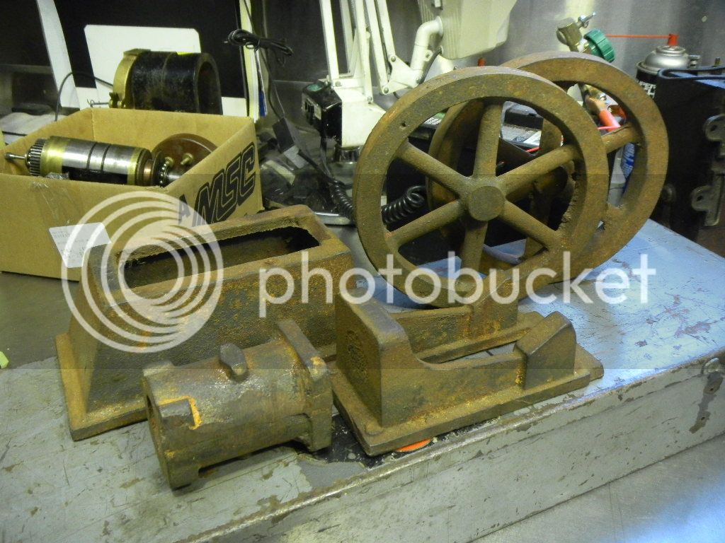
DSCN0798-1.jpg


DSCN0792-1.jpg


I didn’t know what they were at the time but at $25 I figured I couldn’t even buy a flywheel casting for that much.
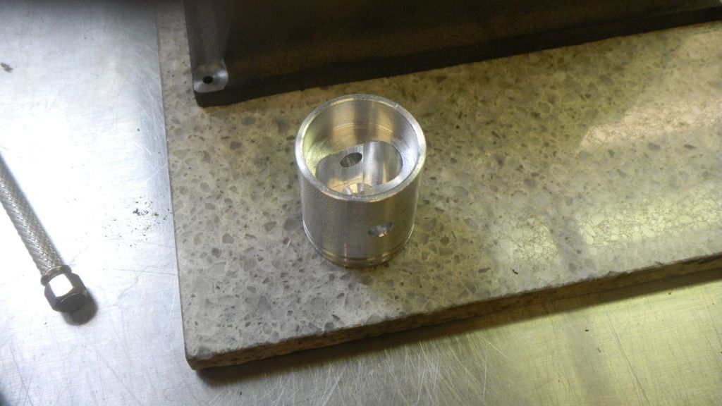
The cylinder casting is pretty rough looking with some sand breakouts and air pockets, giving me the impression that these were cast from an original casting set, but the base, sub base and flywheels looked pretty good.
I posted them here and got a positive ID as a Wyvern, along with some links to pictures and to Hemingway Kits, the English maker of these kits.
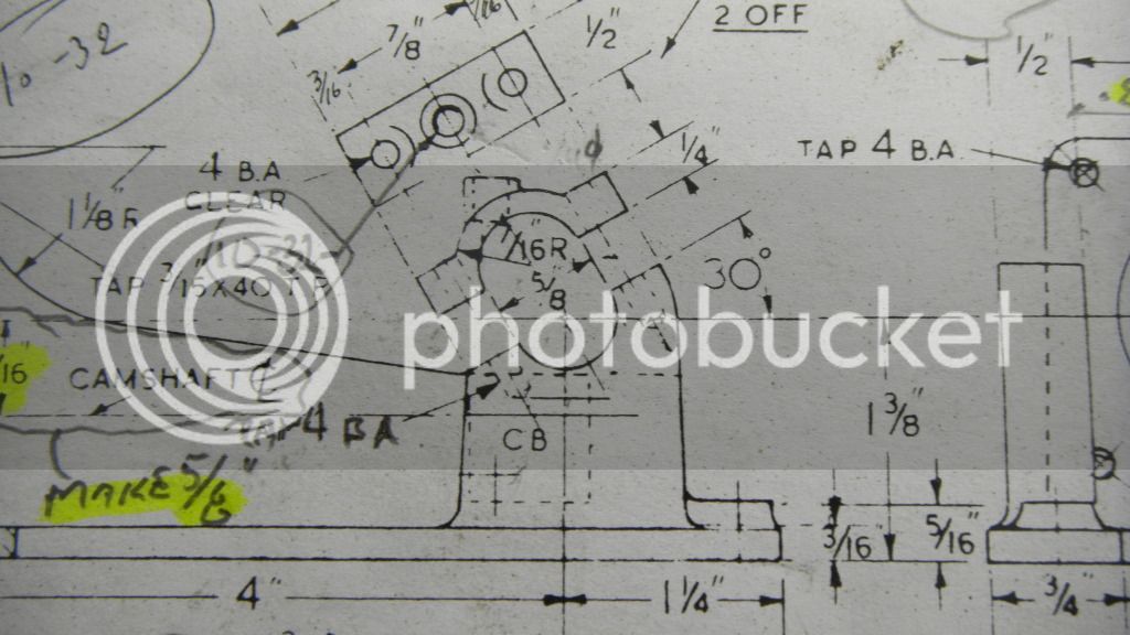
I still needed the rest of the casting and a set of plans.
The plans kind of fell in my lap when I told an acquaintance I had the major castings for a Wyvern. He said his dad had one of these kits and he had an extra set of prints.
That problem solved I was still short the bits and pieces castings, most important being the head and carb body. I got the name of an American producer of the Wyvern and I thought I could get the missing parts from him but after a number of unanswered calls and then finding out that he no longer makes the kits, that idea dissolved. I also considered buying the parts from Hemingway, but they only listed the entire the entire casting set. I never took the time to try to contact them.
The castings sat on the shelf for most of the last year and some months as I was still trying to get my Briesh Little Brother running and I still had my half scale Henry Ford engine sitting on the work bench ALSO in not running condition.

I promised myself I wasn’t going to start messing around with another engine until I got those projects finished and RUNNING.
Even though I kept trying different fixes for the not running Little Brother, I kept hitting standstills as tried to figure out what fix I should try next.
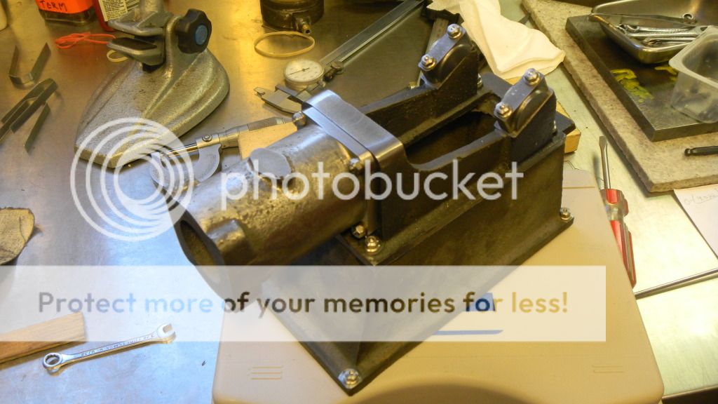
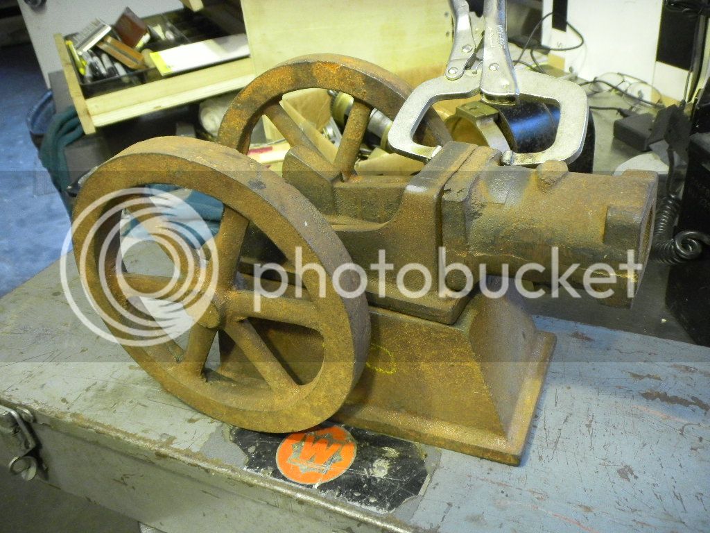
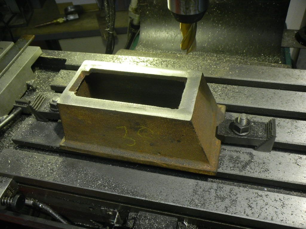
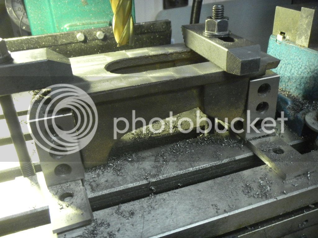
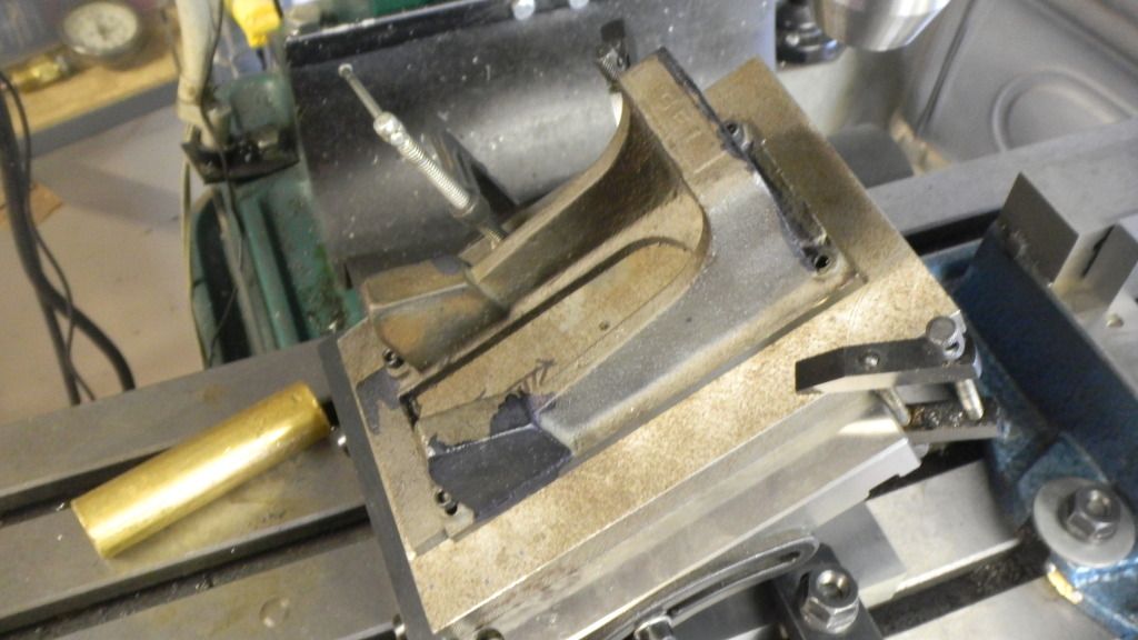
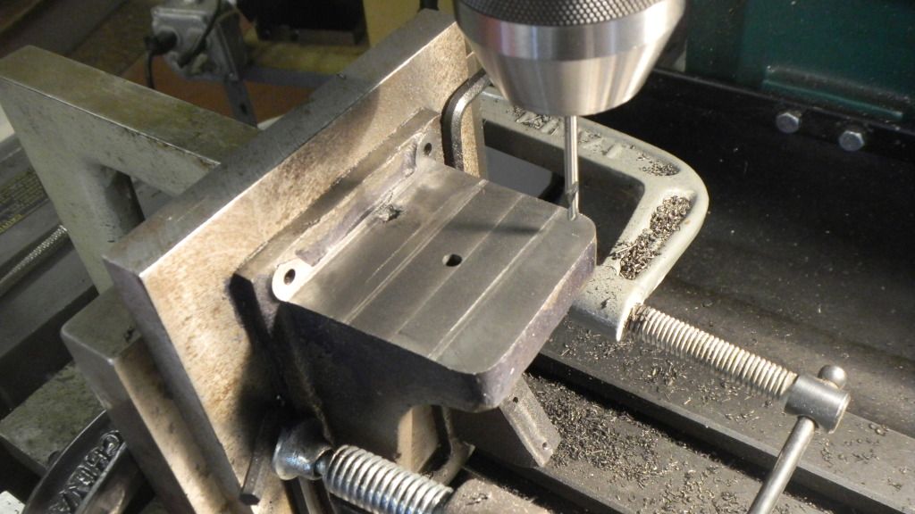
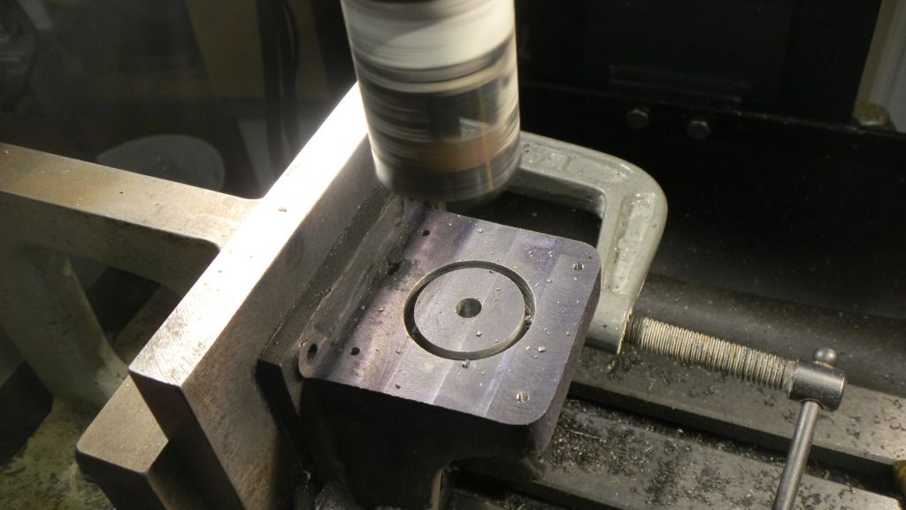
During one of the standstills and wanting to run some machinery, I brought the Wyvern castings out and made a base plate and milled the bottom of the base and mounted it on the base plate I also milled the sub base at that time.
Still, no particular plan as what to do about the missing parts.

DSCN1002.jpg


DSCN1001.jpg


After many hours of and a lot of failed attempts, I’m proud to say that both of my non running projects are now runners.

I’ve actually been working on this model for more than a few weeks now and fully intended to start posting this build a while ago, but work and a few problems with my computer caused me to postpone.
I named this the Wyvernish build because I’ve finally decided to attempt to make all of the missing parts. I have no idea how this is going to work out and I have some of my own ideas I’d like to inject into the project.
It will not be built faithful to the plans, hence Wyvernish.

I'm going to keep working these posts as well as the engine until I catch up to real time.

GUS
 
I decided to sit here and work on another page.

After getting the base and sub base all squared up and milled to the proper dimensions’
I figured that the next step would be to get the lower end (so to speak) started, meaning the main bearing mounts, bearings and crankshaft.
Clamped to my sine plate at the proper angle, I milled the bearing cap surfaces down to the engine centerline, the drilled and tapped the bearing cap mounting holes.

DSCN1772.jpg


I really haven’t got the faintest idea how to use a sine plate properly, I just used an angle block to set it. That’s something else to put on my to do list.
My mill has a tilting head but what a pain in the butt and then I have to try to get it trammed back to square.

Not having a clear plan on how I would fabricate the bearing caps I decided to get the rest of the base machined as per plans as far as I could go before I got to the some of the little items. Which would be the caps and the cam shaft carrier.
I up ended the base and went to work on milling the cylinder mounting surface. Then drilled and tapped the 4-40 mounting holes, also drilled the pilot hole for the sleeve.

DSCN1773.jpg


Then hole sawed undersized and bored it to the correct size.


DSCN1774.jpg


DSCN1775.jpg


I’m really trusting my DROs here, even though they sometimes do strange things, like adding 100 thousandths to the dimension (el cheapo stuff). I would be safer if I did a layout first, and I started to BUT….

Oh well, enough typing for today, I think I heard the Wyvern calling me.

GUS
 
I'll be following along on your build Gus. It looks like it is going to get interesting :)
 
All right Gus!

Another "engine from castings" to follow along with; it looks like you are of to a great start.

Keep the updates coming.

Dave
 
Nothing wrong with setting a sine plate (or any other fixture) with an angle bar. Without gauge blocks it's about the only accurate way.
 
I wanted to get going on the crankshaft and connecting rod but the material I ordered hasn’t got here yet. So I decided to cook up a scheme on how to make the bearing caps.
Planning ahead would have been good here. I wanted them to be cast iron, and the only piece I have is a 1” round I used for pistons, also I don’t have the proper radius mill and I would have to make an insert for the oiler cup boss, as I can see no way I would come up with the shape otherwise.
It didn’t take long to realize that it would be easier for me to learn foundry and pattern making rather than scratch build the shape. I don’t have the experience.

It "ALMOST" makes me wish I had the rest of the castings, I'm starting to think this is really going to be a fight to the finish.

DSCN1869.jpg


Back to the think tank and my new scheme would be to clone the cast iron caps on my Lil’ Brother model, a lot easier to carve. I still wanted cast iron, so cast iron it would be.
Not wanting to wait to order some bar stock I decided to sacrifice a couple inches if my 1”spun cast grey iron bar.

DSCN1782.jpg


After making a pile of chips I had a nice looking piece of bar to carve the caps out of.

DSCN1783.jpg


Then a little more machine work to get two pieces identical length and I drilled and bolted them together with a touch of Loctite 609 in between. I didn’t want them moving around in the lathe.

DSCN1788.jpg


PIC 1788
 
Then on to the little 4 jaw chucked in the bigger 3 jaw. A few more chips and this appeared. I new it was in there all the time. :)

DSCN1789.jpg


DSCN1790.jpg


Thanks to the 609 I had to put them in the bench vise and had give them a pretty good whack to break the bond.
But they came out pretty nice.

DSCN1793.jpg


I still have some work to do on the base around the bearing blocks, but I’m still thinking about what I actually want.

GUS
 
Still waiting for the material I ordered for the crank and conn rod, so, I took a long hard look at the cylinder. Not very pretty and I was not looking forward to boring it let alone trying to clean up the sand breakouts, air pockets and parting line. I’ve been wondering since I first got the castings if it would even be useable.
Another worry , would I have enough room left on the flange end for bolts or even tiny screws.
I decided to at least machine the mounting surface the and drill the mounting holes, and that went without a hitch.

DSCN1776.jpg


Then , maybe, I would be able to figure out what actually needed to be done to clean it up. UGH!!!! What a mess!

DSCN1779-1.jpg


DSCN1780-1.jpg


DSCN1781-1.jpg


I new I would probably have to try turning it on the lathe, but the water line bosses confused the issue.
 
 
I decided to clamp the cylinder in the mill vice and just mill enough material out and the file the rest.
Another mess, this time I got into it by myself.

I was a little to fast coming at it with the end mill and almost as soon as the mill touched it twisted in the vise, put a gouge in the cylinder and broke a brand new 5/8” mill. I can’t find the picture at the moment but it will show up.
I have to put the gouged side on the bottom, maybe no one will notice, but I’ll always remember it’s there.
At any rate I decided on the 4 jaw in the lathe and just cut away at it like Edward Scissorhands. Out of the lathe and into the bench vise for some serious file work. It actually came out fairly nice for how bad it looked before.
I somehow forgot to take pictures of that operation. See the last picture in this post.
I’ve been calling this the cylinder, but it is actually the cylinder jacket, which reminds me I still have to bore it for the cylinder and the hollow it out some to form the water jacket, and I still have to make the cylinder.
I’ve not had a lot of practice boring things (although my wife seems to think differently), and I’ve had difficulties with that operation.

I’m not looking forward to it (I think I already said that), so I’m going to postpone the inenvitable and do something a bit easier.
Make a few studs, nuts and washers. Material of choice is stainless steel.
I enjoy making hardware, a lot of repetitive operations but it’s almost “stupid work”, a kind of job like painting where you don’t have to think a lot about what your doing and it looks good when your done.
And if you mess a few up it’s not a big loss.
I use hex stock for the nuts and threaded rod for the studs and round stock for washers.
The nuts and washers in the lathe are a drill, tap for the nuts, file, sand and cut.
Cutting the threaded rod to uniform lengths got a lot easier for me when I tried something different than just holding the rod in the vise.
I folded a piece of light gauge aluminum over the rod and squeezed it in the vise, more or less forming a thread. Loosening the vise and screwing the rod out to the proper length plus the width of the hacksaw blade gave me a more exact cut.

DSCN1798.jpg


DSCN1804.jpg


End result is a lot more appealing to me than stock hardware.
 
DSCN1808.jpg


Back to the shop. I think I might have some staightening to do.

DSCN1895.jpg
 
Still avoiding the boring operations, I decided to work on some of the machine work around the bearing caps.
The areas on the inside of the base would be milled flat to the surface of the caps for the bearing flanges as well as the area below the camshaft side to make the mounting surface for the camshaft bracket.
Still not sure what I should do for the opposite outside surface I decided to just drop a 1” mill on it to match the circle of the cap. If I don’t like the look of it I can always just mill it flat later to match the other side.

DSCN1826.jpg


Now to bore the main bearing holes. I centerd on the layout dimensions drilled it a tad undersize and bored it with the boring head. I should have just enough length on the boring tool to just make it thru the bottom hole.

I got surprised when the upper shank of the tool wouldn’t fit thru the upper hole and stopped progress at about 1/16” into the bottom.

DSCN1829.jpg


Not wanting to, but not having a longer cutter I did a “ Hail Mary” play and flipped the casting over recentered using the same coordinates and held my breath as I bored the rest of the hole.
I breathed a sigh of relief when I put a 5/8” bar thru both holes with no argument, a nice snug fit.

DSCN1831.jpg
 
I can't help but ask this question. Is this post in the wrong place, should I have posted this in "Engines from Castings" ?
If so somebody please move it, I don't know how.

Judging on my experience cruising that venue some time ago , I've seen more questions about castings/kits, than actual builds, or is it just me.

Dave, I was suspecting, from your new avatar, that you might have started to work on the Pacific Vapor Engine and I found it yesterday.

Way Cool!! 'Bout Time!
 
But I'll continue, I'm indulging myself!!;)

Still avoiding the boring operations, I decided to work on some of the machine work around the bearing caps.
The areas on the inside of the base would be milled flat to the surface of the caps for the bearing flanges as well as the area below the camshaft side to make the mounting surface for the camshaft bracket.
Still not sure what I should do for the opposite outside surface I decided to just drop a 1” mill on it to match the circle of the cap. If I don’t like the look of it I can always just mill it flat later to match the other side.

DSCN1826.jpg


Now to bore the main bearing holes. I centered on the layout dimensions, drilled it a tad undersize and bored it with the boring head. I should have just enough length on the boring tool to just make it thru the bottom hole.

I got surprised when the upper shank of the tool wouldn’t fit thru the upper hole and stopped progress at about 1/16” into the bottom.


DSCN1829.jpg

Not wanting to, but not having a longer cutter I did a “ Hail Mary” play and flipped the casting over recentered using the same coordinates and held my breath as I bored the rest of the hole.
I breathed a sigh of relief when I put a 1/2” bar thru both holes with no argument.

DSCN1831.jpg


Wow, Going back thru my build, I just now realized I somehow posted the the same thing twice. Senior moment I guess.
 
Last edited:
Knowing I would have to face my nemesis sooner or later, I decided it was time to bore the cylinder jacket.
I’ll add that boring on the mill has become a breeze since I picked up a used Bridgeport boring head, the old Chinese head I had was almost unpredictable, except for the fact that what I bored was usually oversize.

Boring on the lathe, however, is another story.
OK, I had a brain fart, maybe two. Try not to laugh.

DSCN1834.jpg


Not wanting to have to pull off the 6” 3 jaw and put the much heavier finger smashing 8” 4 jaw on, I devised a plan where I would mount the cylinder jacket on a 3” chunk of aluminum round I had previously used for making a bronze bearing for a real size engine, and simply mount it in the 3 jaw.
As things go something was wrong with my centering, still not wanting to mess with the big 4 jaw, I opted to stuff the jig in my little 4 jaw in my 3 jaw.
And boring it had it’s problems. Although I was using a 5/8” dia boring bar the bore tapered in toward the chuck end, not just a little but a lot.
I had no difficulty cutting the outside of the jacket, so I put it off to chill spots in the iron and just persisted in boring taking very light cuts with two runs per increase. At some point, when I checked, the bore had straightened out. Wow, I’m good, I thought, sometimes a brain fart works no matter how it looks.


Then to drill and tap the inlet and outlet bosses.

DSCN1836.jpg


I didn’t figure out until I started boring the cylinder, that the boring bar was too big for the starting size of 1" starting hole. The carbide tip would start cutting but the allen head lock lug for the insert started dragging very shortly after entering the bore, causing the bar to deflect.
The insert was limited as to the depth of cut, as the bore widened it got large enough to clear the screw.
Speaking of screws, I’m lucky I didn’t screw up both pieces.


I used a piece of the 1 ½” dia. Iron bar about a half inch longer than needed. Chucked in the 3 jaw, did the inside first and the cut the OD and formed the rim before cutting off.

DSCN1853.jpg


The cylinder came out beautiful inside and out and the dimensions were spot on.
Instead of a light press fit, I opted for a snug fit to be fortified with Loctite.

DSCN1854.jpg
 
Because I had it, I tried a piece of 1 ¼” alum bar in the new cylinder, nice snug fit.
Ready made piston.

Skim 1 or 2 thou,

DSCN1891.jpg


Bore the end a bit,

DSCN1897.jpg


cut a couple grooves and part off.

DSCN1898.jpg

Ready for the mill.

DSCN1899.jpg
 
Drill and ream wrist (gudgeon) pin

DSCN1900.jpg


Upended in mill vise and using a brass rod to indicate square.

DSCN1902.jpg


Bore the small end pocket with an end mill and, whamo, new piston.
Notice there are no set screws for the gudgeon (wrist) pin. The pin floats and uses brass discs to protect the cylinder wall.

DSCN1903.jpg


Whew!!!, I'm all typed out.

I'll almost welcome having to start a new work assignment tomorrow morning. Five weeks or so (coming home weekends), but next weekend is my local engine show, can't wait and can't miss it.
All the grandkids and nice weather predicted. We can play with some full size engines and, of course, my models.

This means no shop time for a while (maybe not a bad thing), but I may be able to get enough time next Sunday to catch up on my last two posts and can get to real time posts.

GUS
 
Wow Gus,

You are making great progress on the Wyvern; it's always fun when you can get a block of uninterrupted shop time to work on a project.

As far as the sub forum goes I'm not sure what to say; I know members some of them gone now posted casting projects in the work in progress section. After all it is a work in progress; I'm not sure what Rick intended when he originally set up the forum except maybe it was based on bar stock builds and then along came the castings?

I parked my build there (Engines from Castings) because it seemed appropriate; but I wonder if the work in progress gets more traffic?

I think either way that it really doesn't matter.

Keep up the great work,
Dave
 
Nice progress, Gus. You've done those castings right proud.

Chuck
 
I am enjoying your build Gus even though I don't use castings and work on a much smaller scale. I take pleasure and encouragement from all the work that people share here and wherever you hide your build I will find it ;)
 
Gus

Just came across your build. I really liked the way you put your thought to paper (computer in this case). Pulled up a chair and will be following your progress as you go along.

Vince
 
Well, I put my 60 hours in 4 days into the work assighnment (spelling?, doesn't look right but..don't give a rats A>>>.), I'm pooped, but I'm home. Going to the engine show tomorrow,:D yeah, good.

Thanks for the words of encouragement

Dave, I had the same thoughts, but seems like a lot more, possibly more than one person can take in, happens on this sub forum. I don’t think I could follow all these builds if I dedicated all my time to it, but it’s all good. Something for all.
I’m feel humbled by the quality of your build, I could only wish to attain your skills, but it sure makes good reading and maybe, I’m sure, can retain some of it.

Chuck, I followed your pipe fitting engine build with great interest and was impressed by the many different approaches you tried when things didn’t meet up to your expectations.
It gave me the push I needed to carry on with my H. Ford.

Prod Engine, Vince. I’m not the sharpest tack in the box, but I enjoy building, and writing (in that order) , thanks. I will include my blunders and my perceived accomplishments as this build progresses.
A screw up (in my world) is a wonderful learning instrument, and I always learn from the many.

Thanks
GUS


Latest posts

Back
Top