Wyvernish Build

Home Model Engine Machinist Forum

Help Support Home Model Engine Machinist Forum:

This site may earn a commission from merchant affiliate links, including eBay, Amazon, and others.
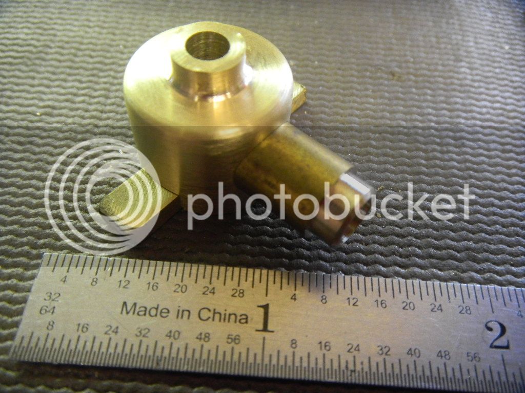
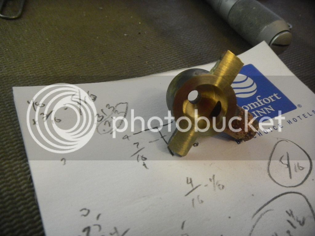
:-\Having completed the most difficult part of this build, so far, the rockers arms, now I can play with making the intake valve push rod and lifter mechanism.
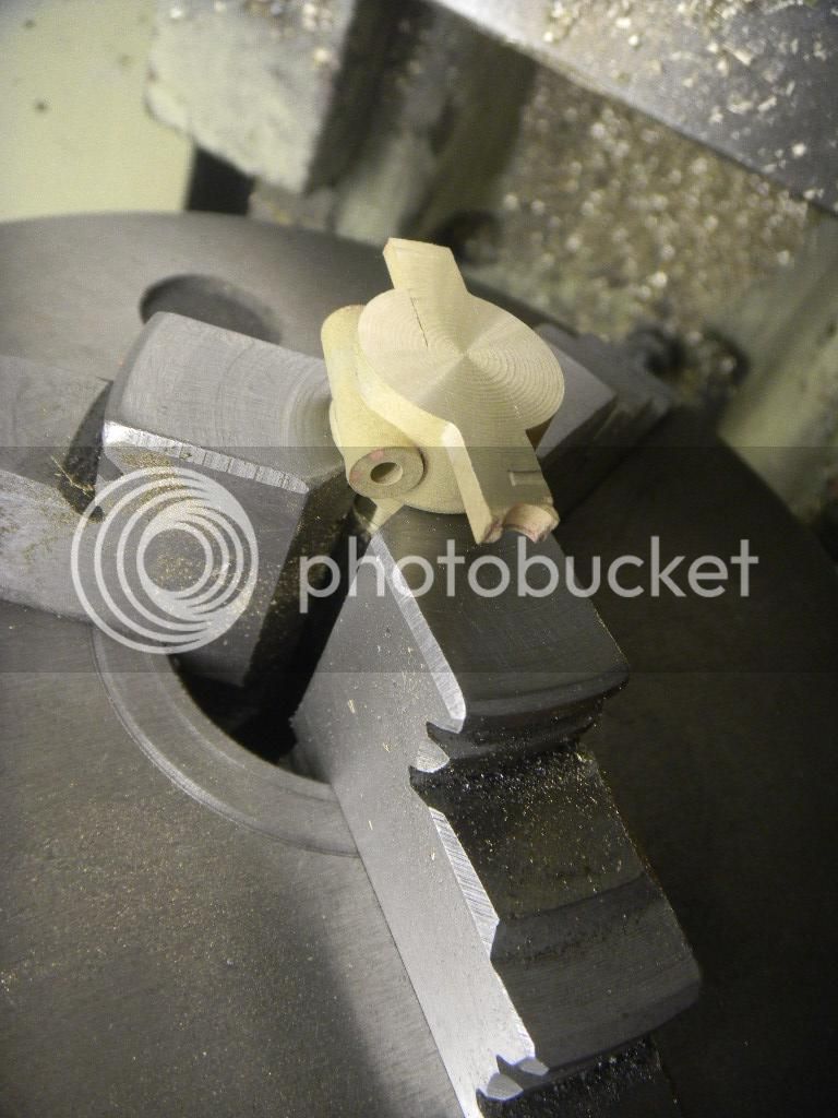
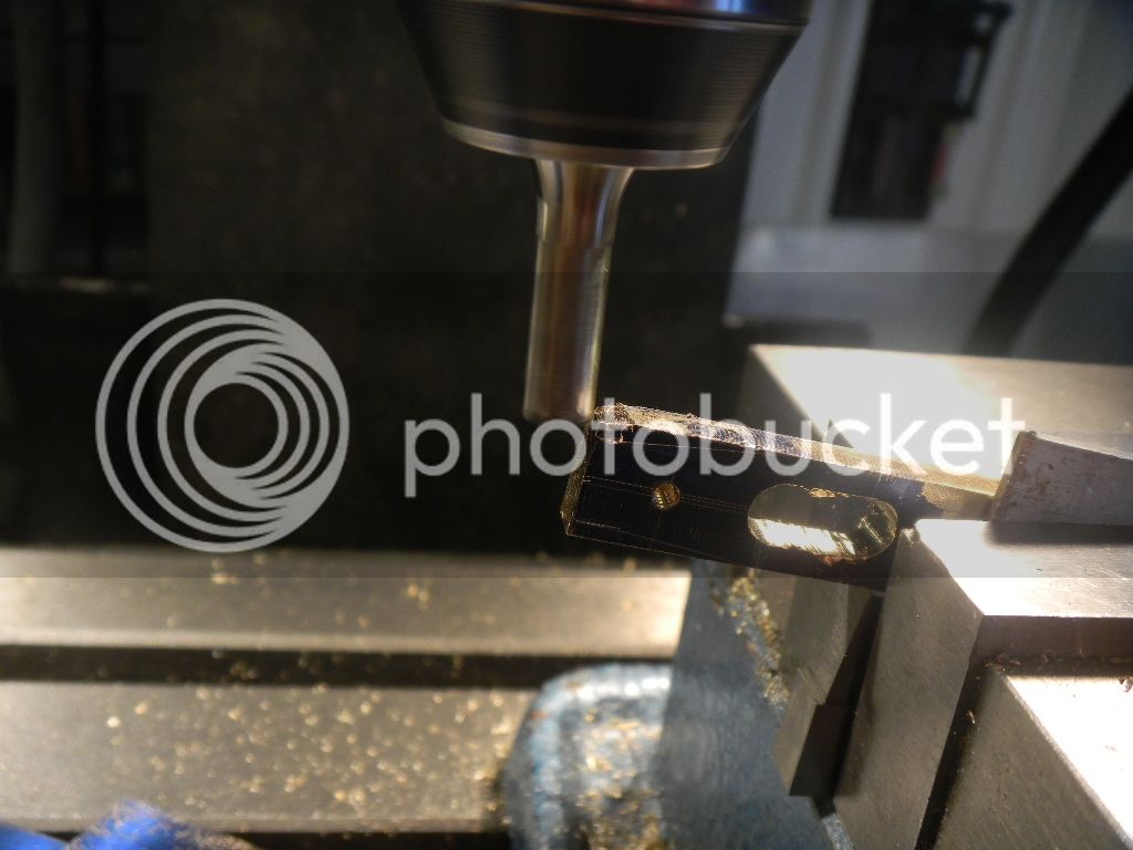
The lifter has a roller actuated by the cam and a slot which guides it via the side shaft.
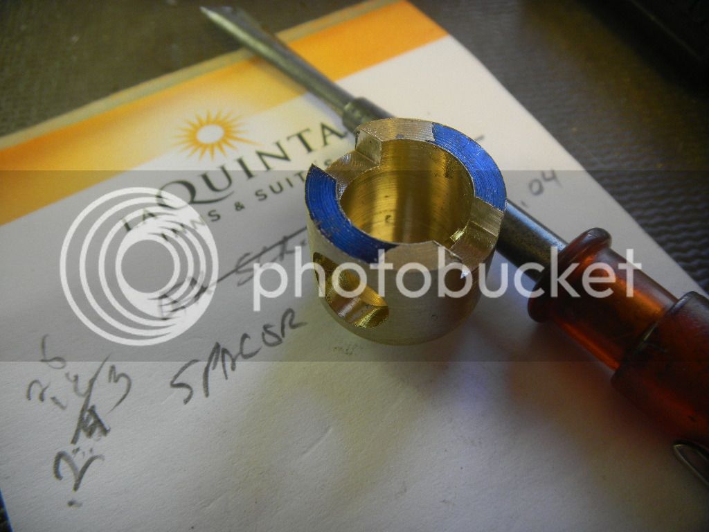
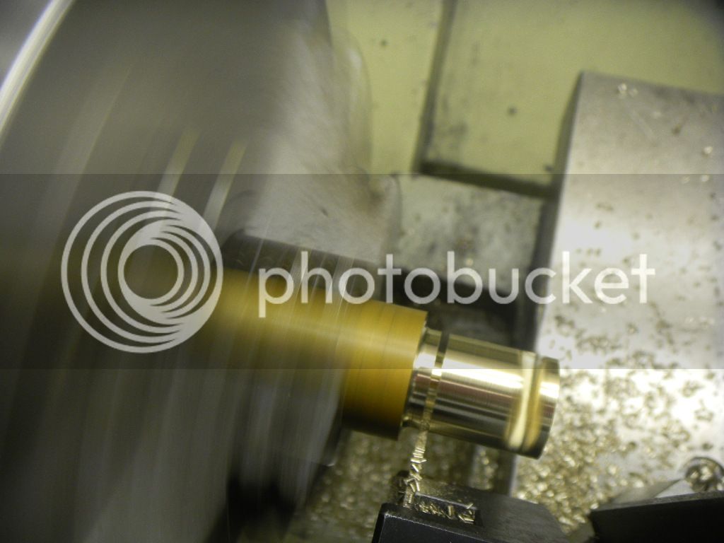
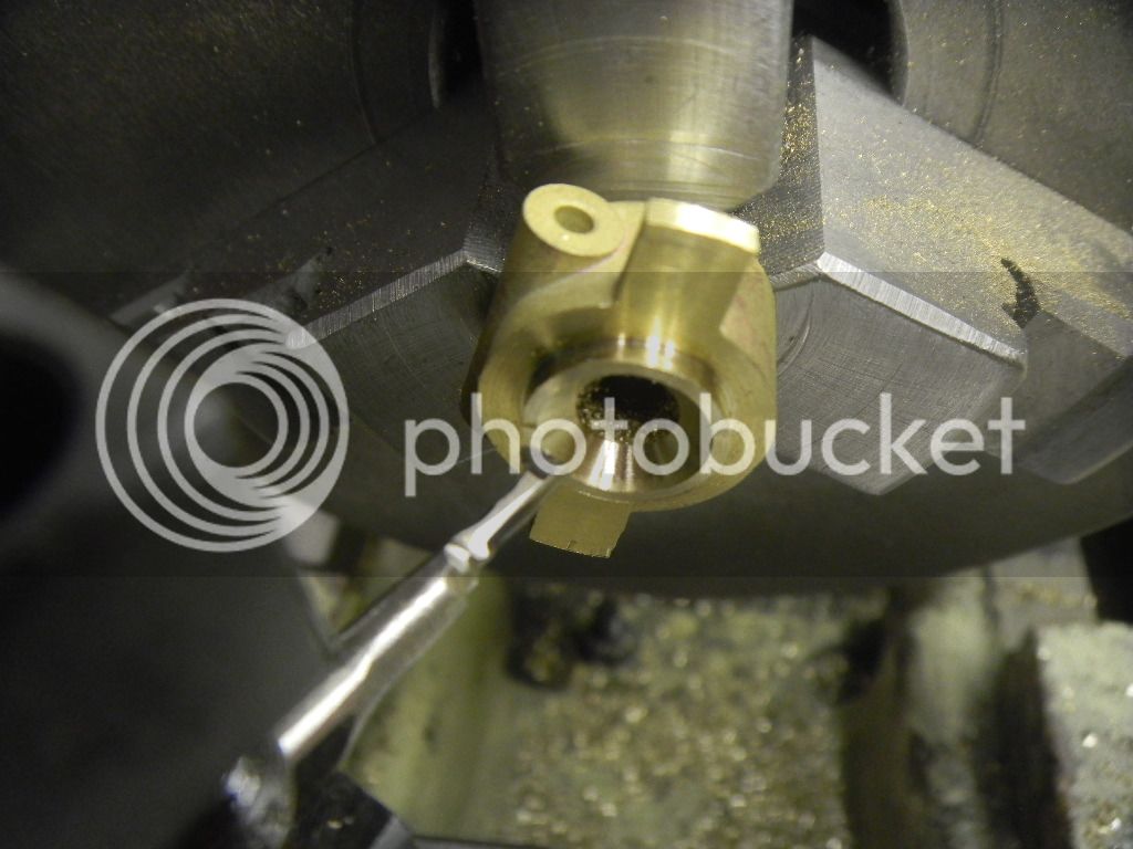
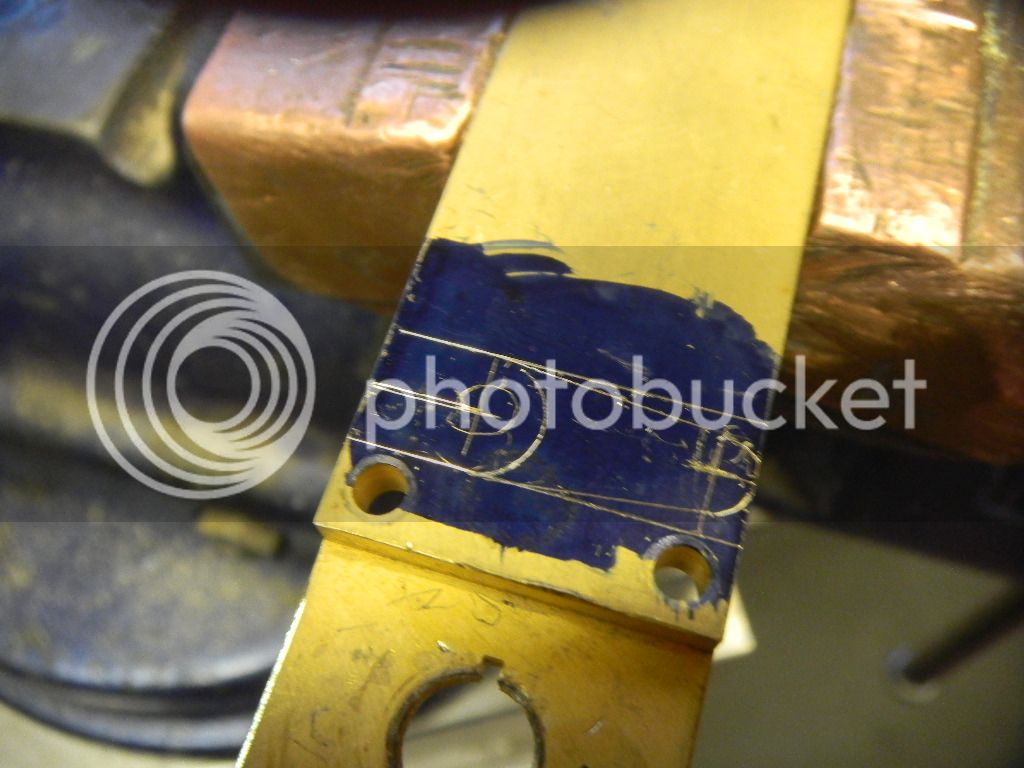
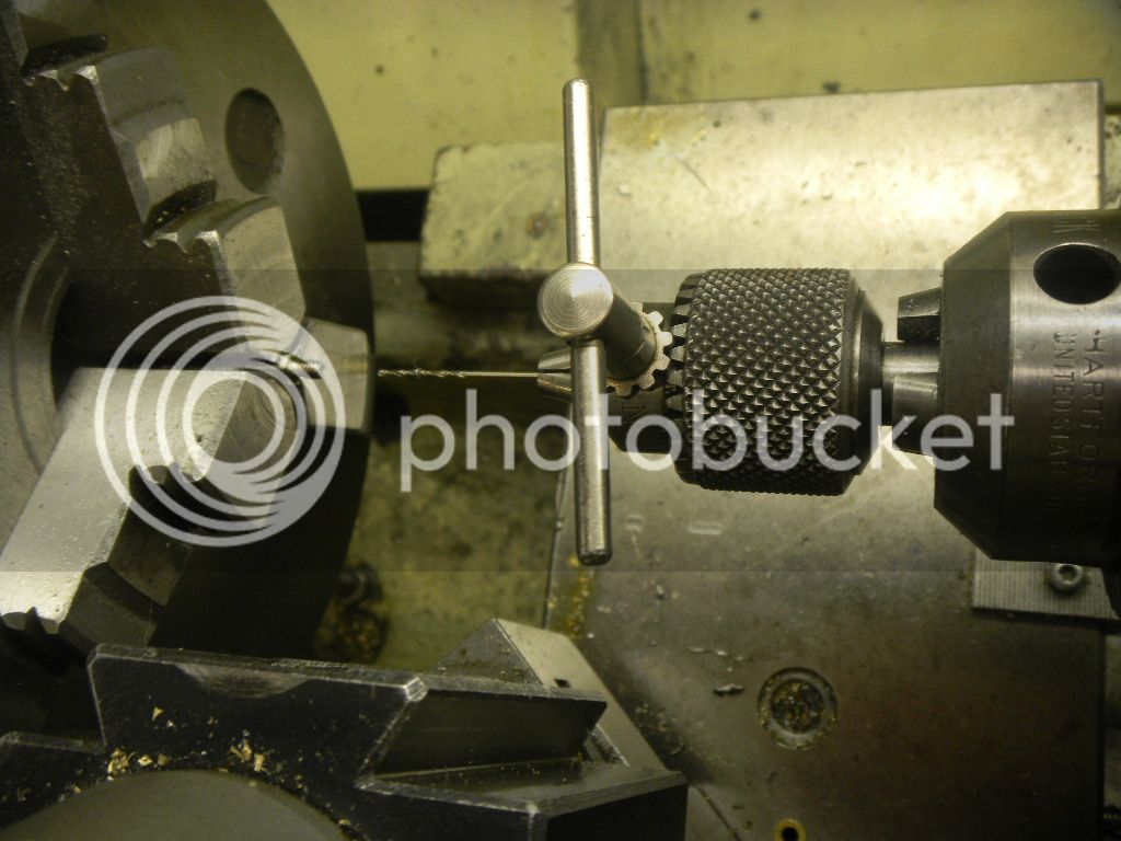
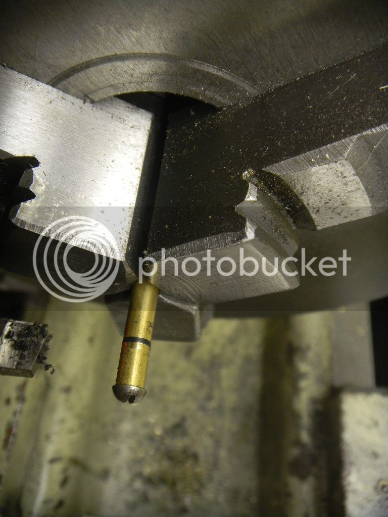
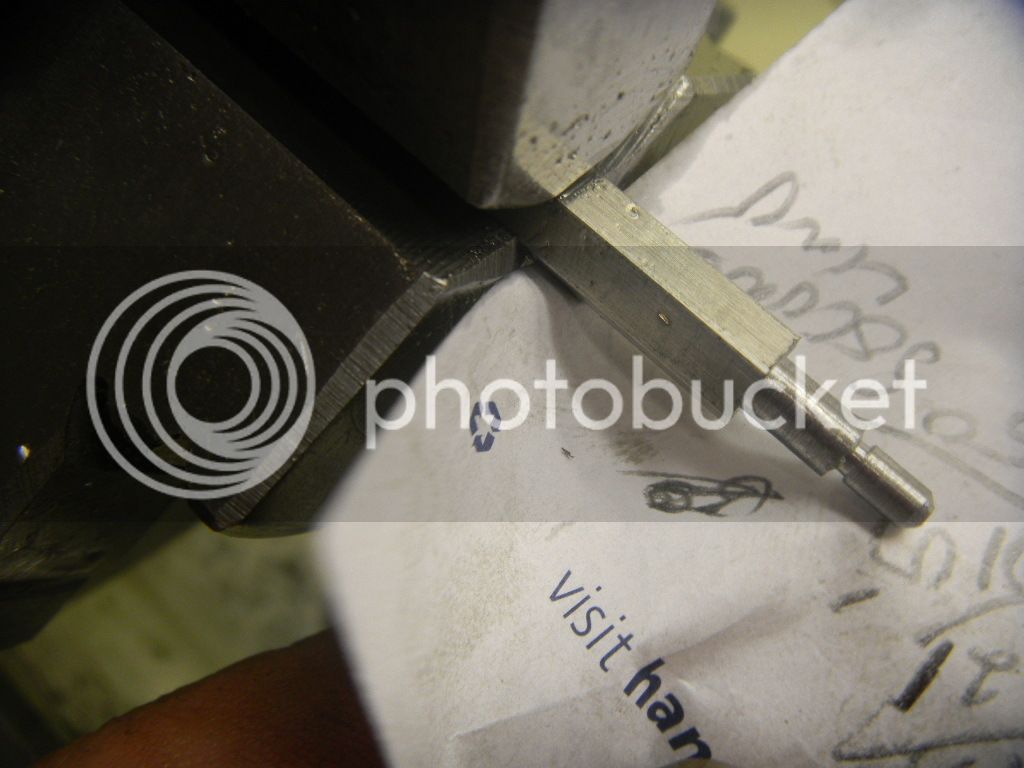
First, milling the slot….

DSCN2546.jpg


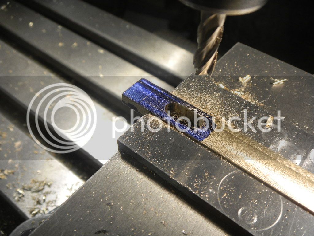
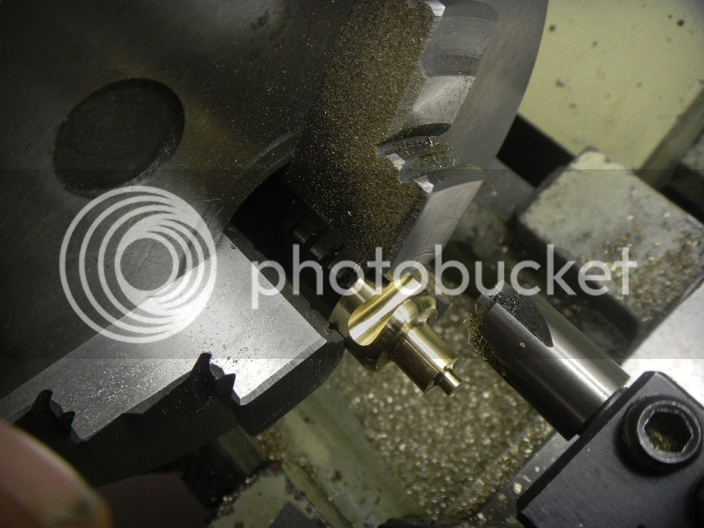
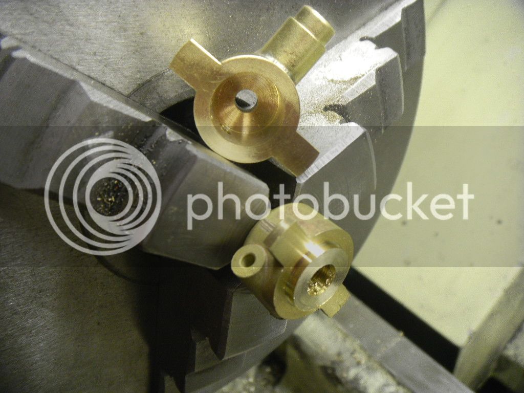
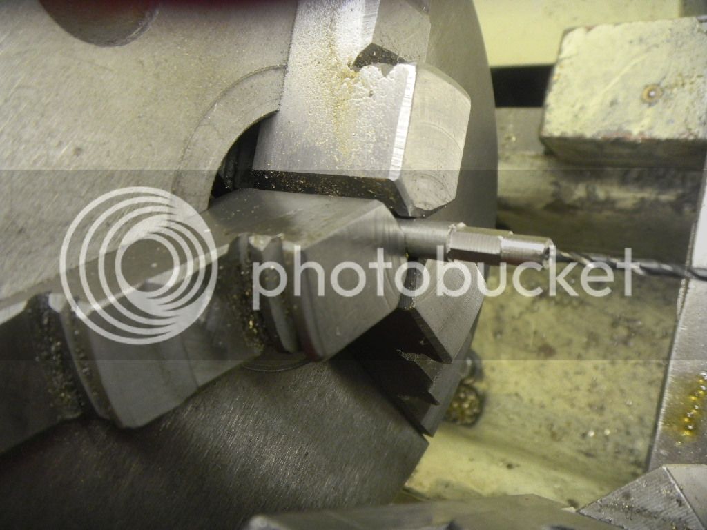
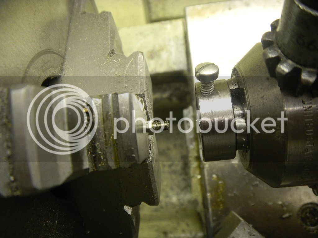
The roller mounting hole drilled and tapped, then the decorative tapers cut in the sides.

DSCN2547.jpg


DSCN2548.jpg


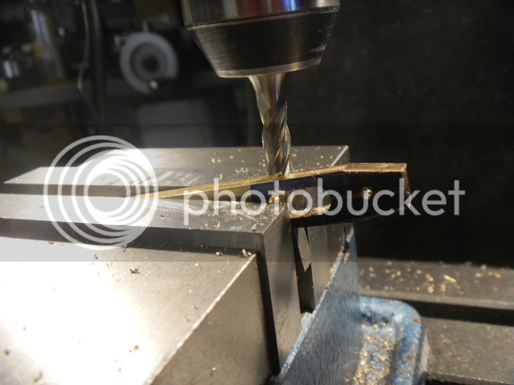
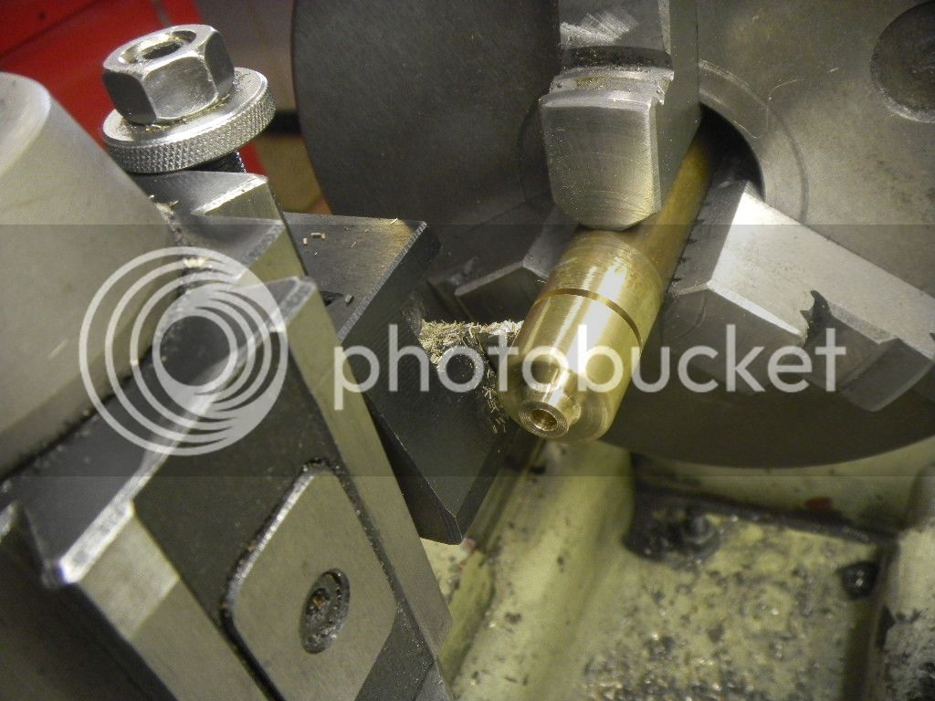
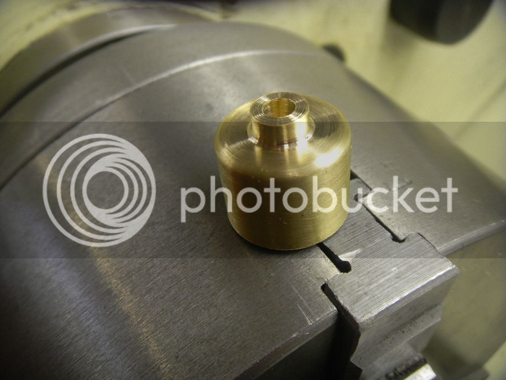
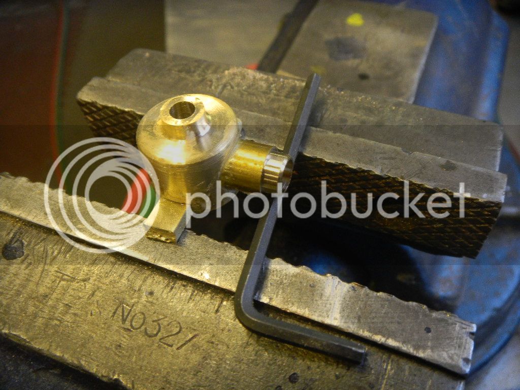
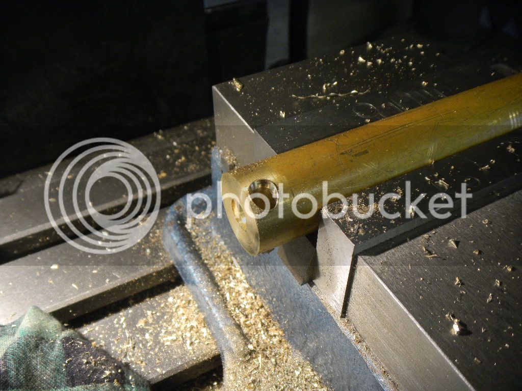
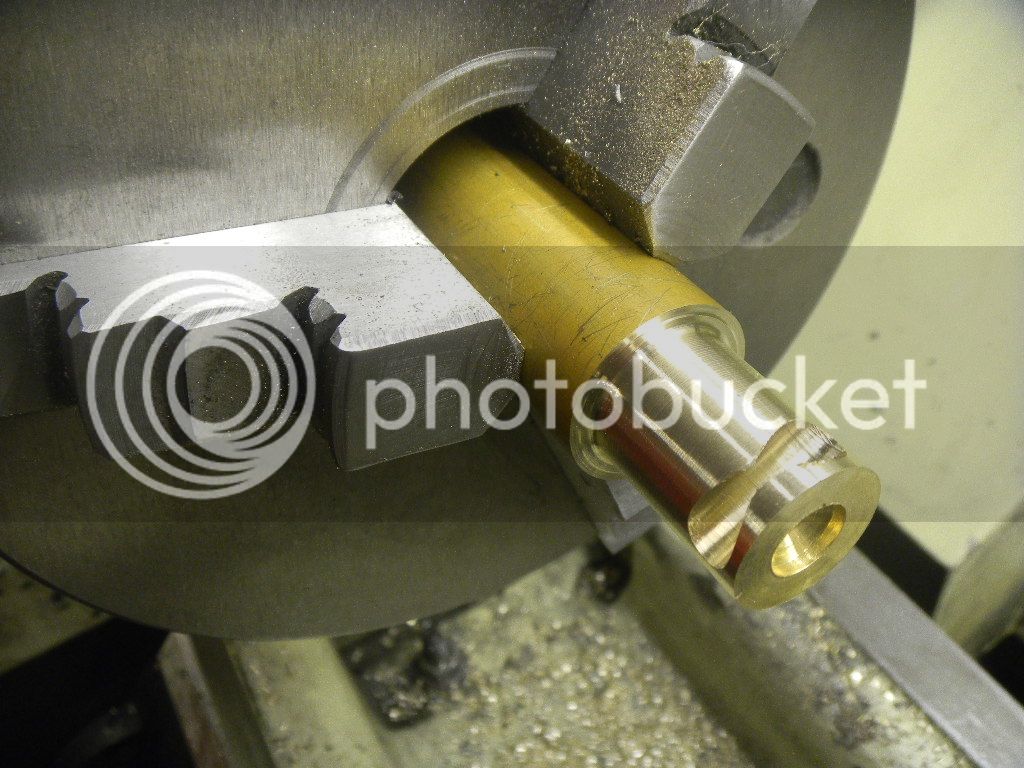
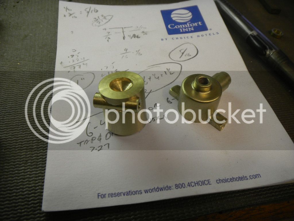
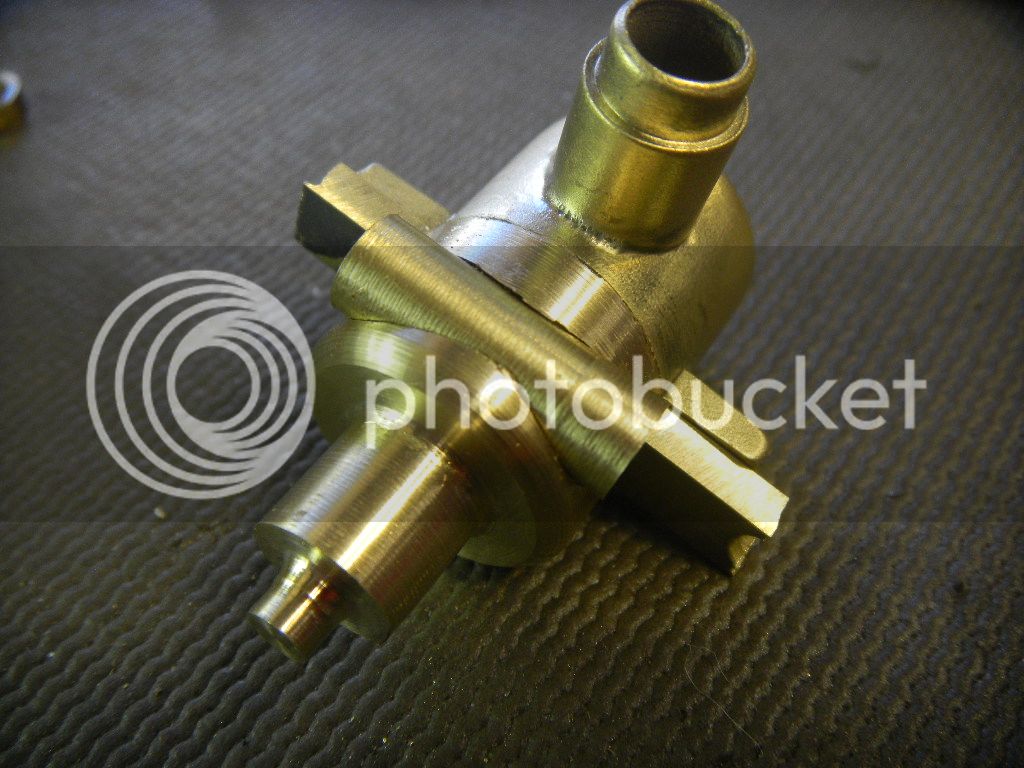
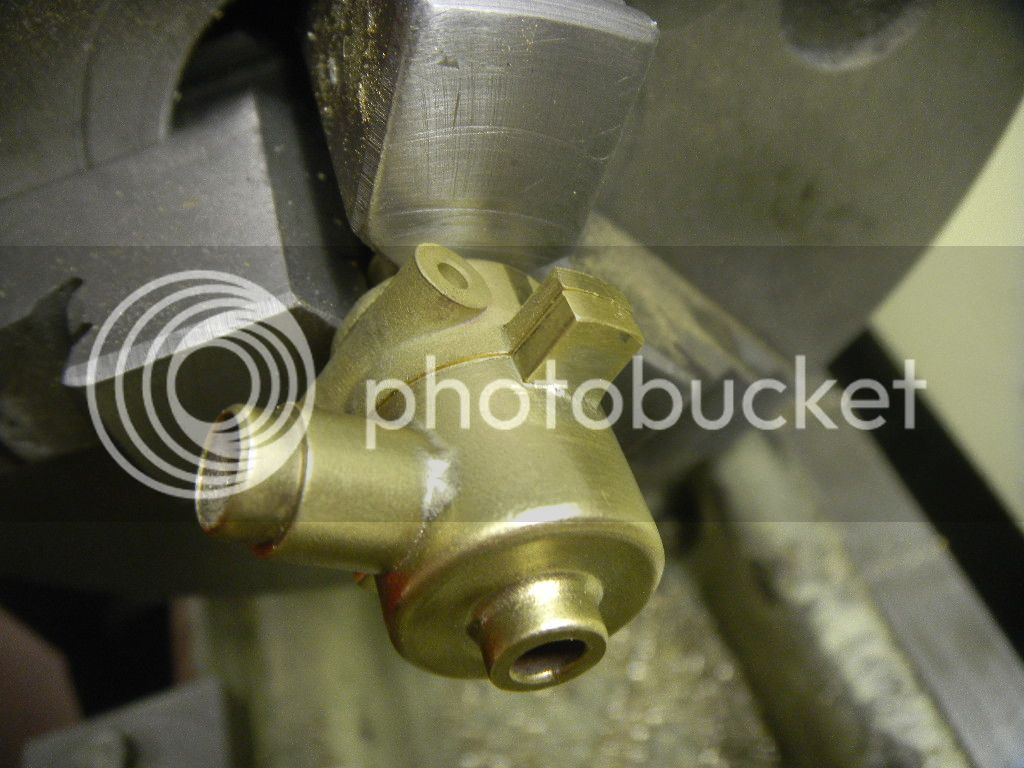
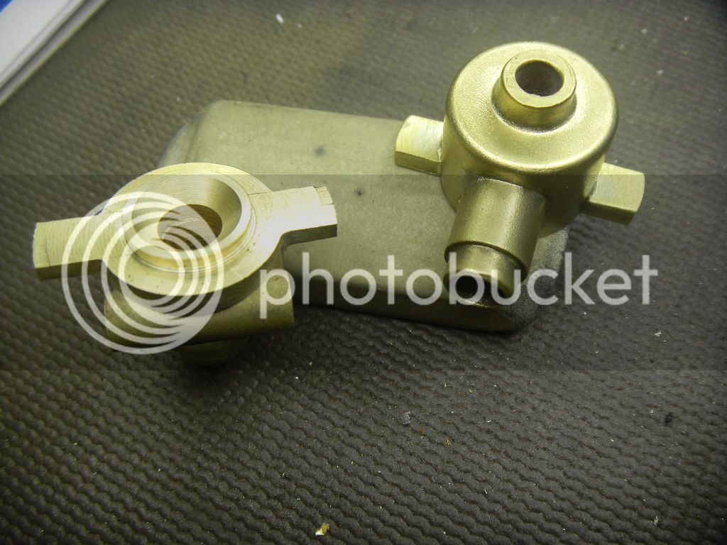
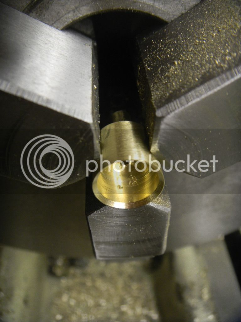
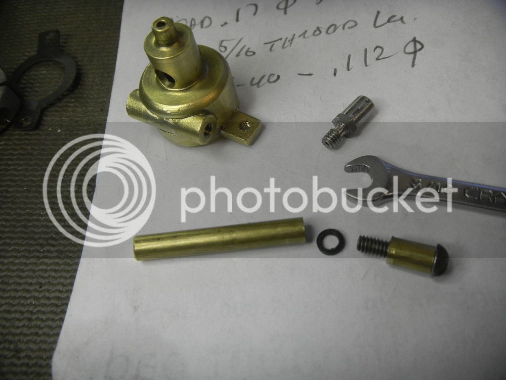
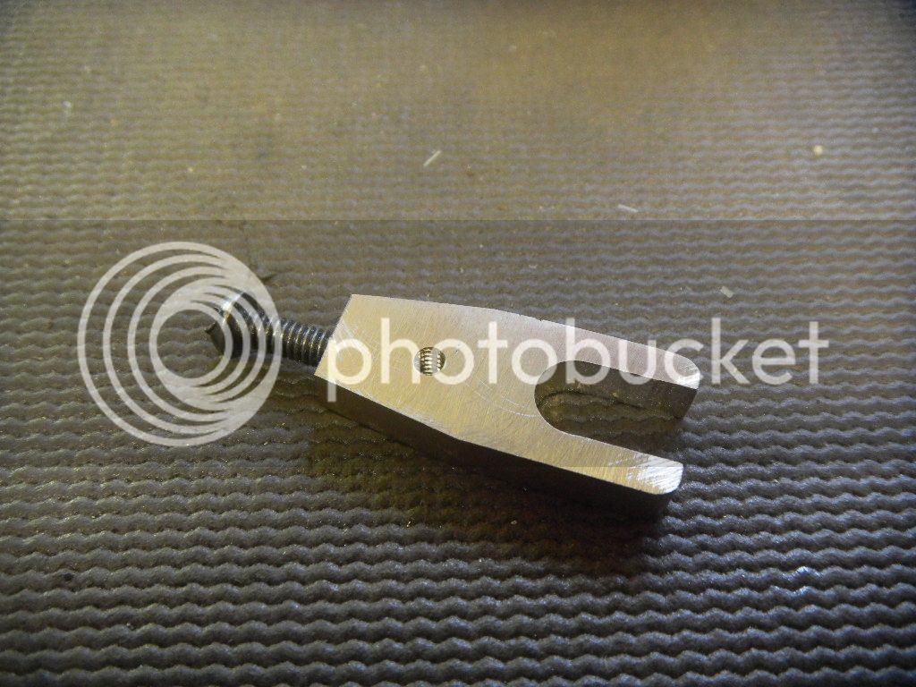
The push rod hole also drilled and tapped, the part was cut off from the brass bar, then shaped and cleaned up a bit.

DSCN2549.jpg


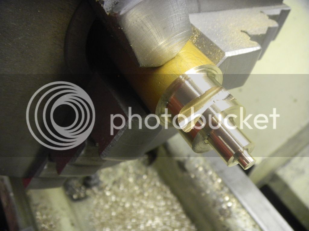
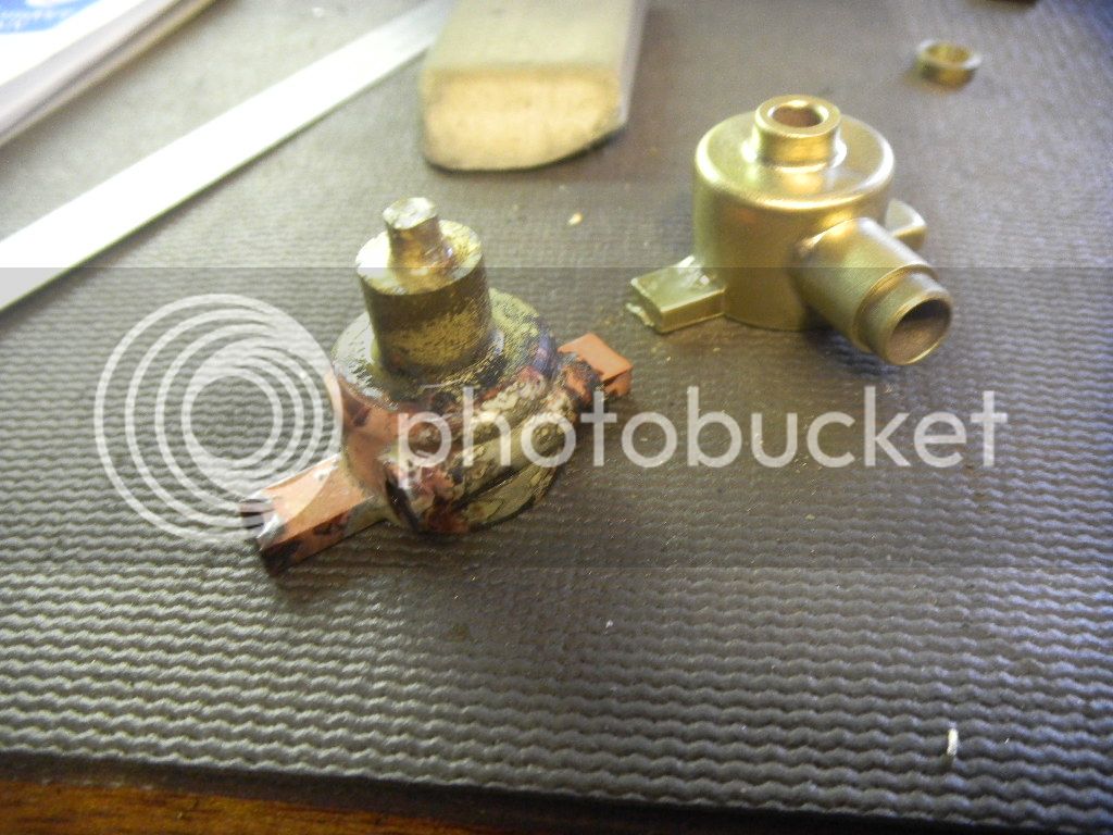
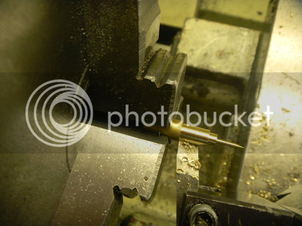
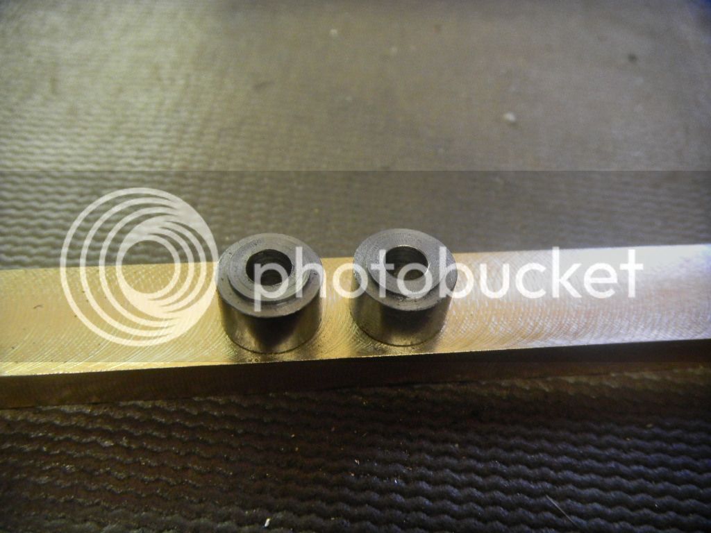
A pair of cam rollers cut from SS bar stock.

DSCN2550.jpg


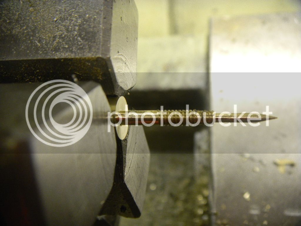
Then three almost identical shoulder screws made from ¼” SS hex. One for the lifter and two for the rockers.

DSCN2553.jpg


DSCN2555.jpg


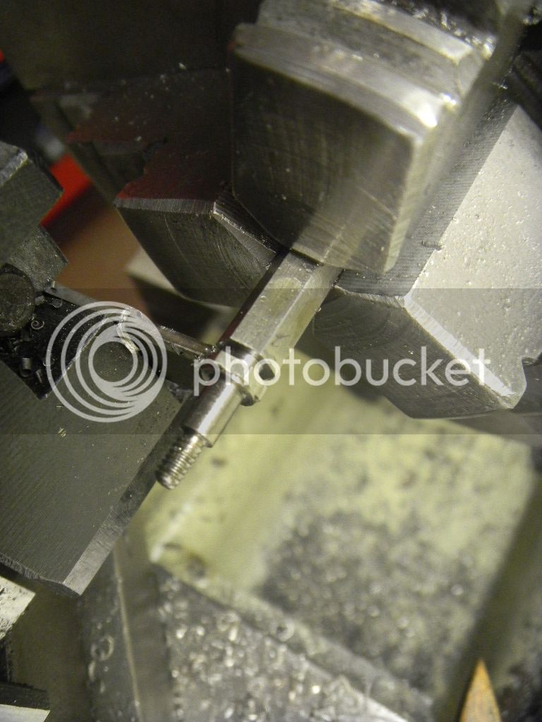
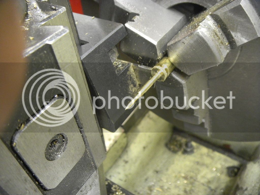
Then a little push rod cut and treaded for the lifter.
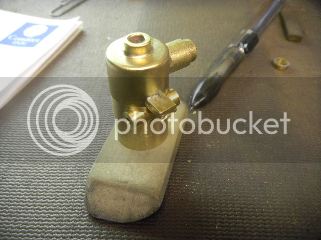
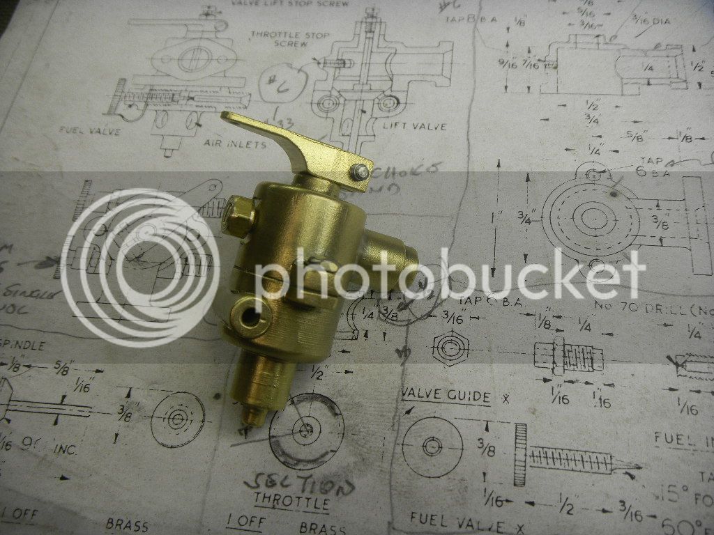
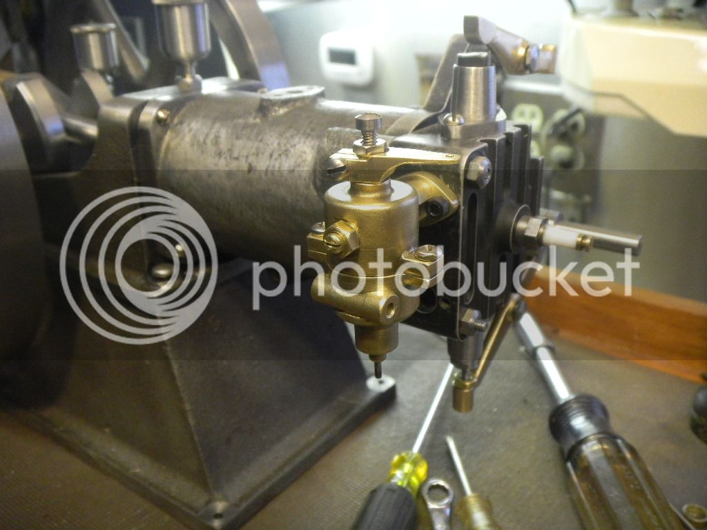
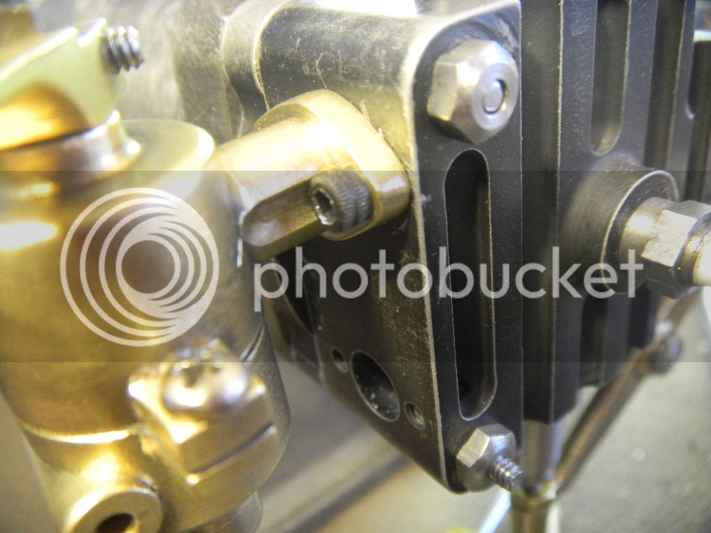
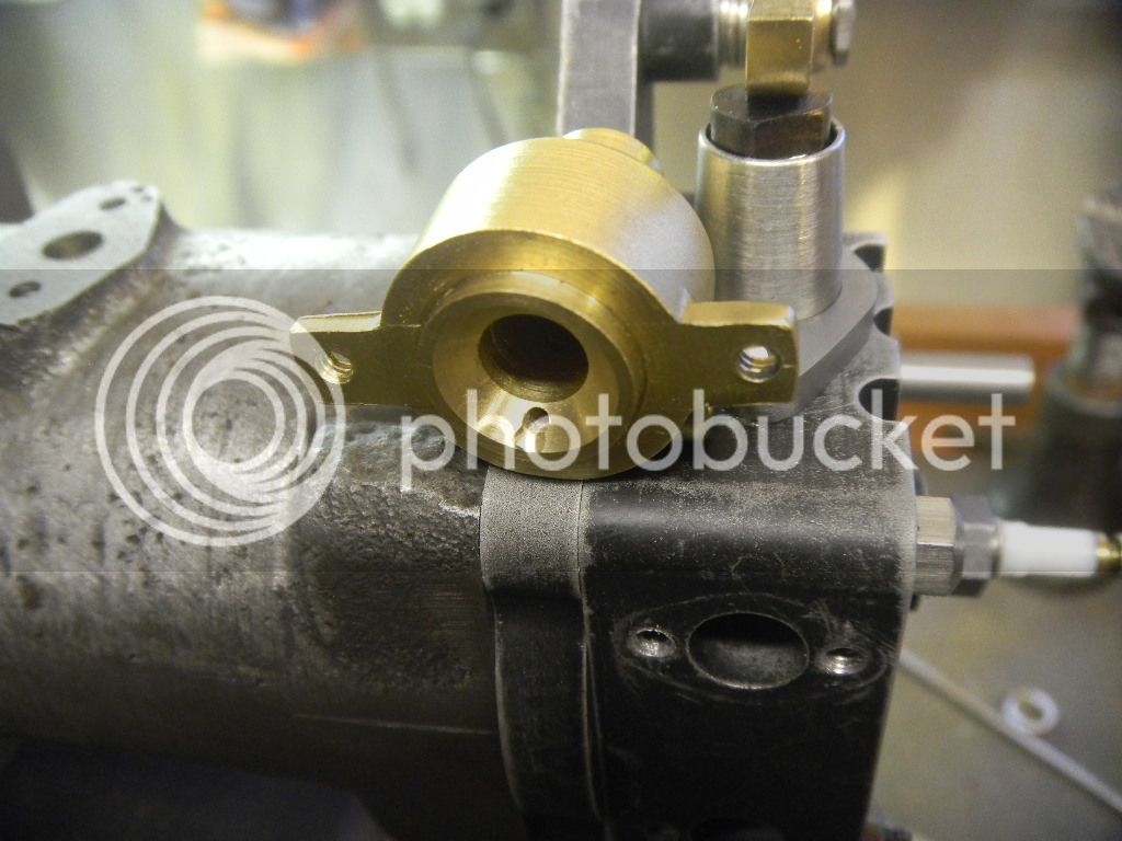
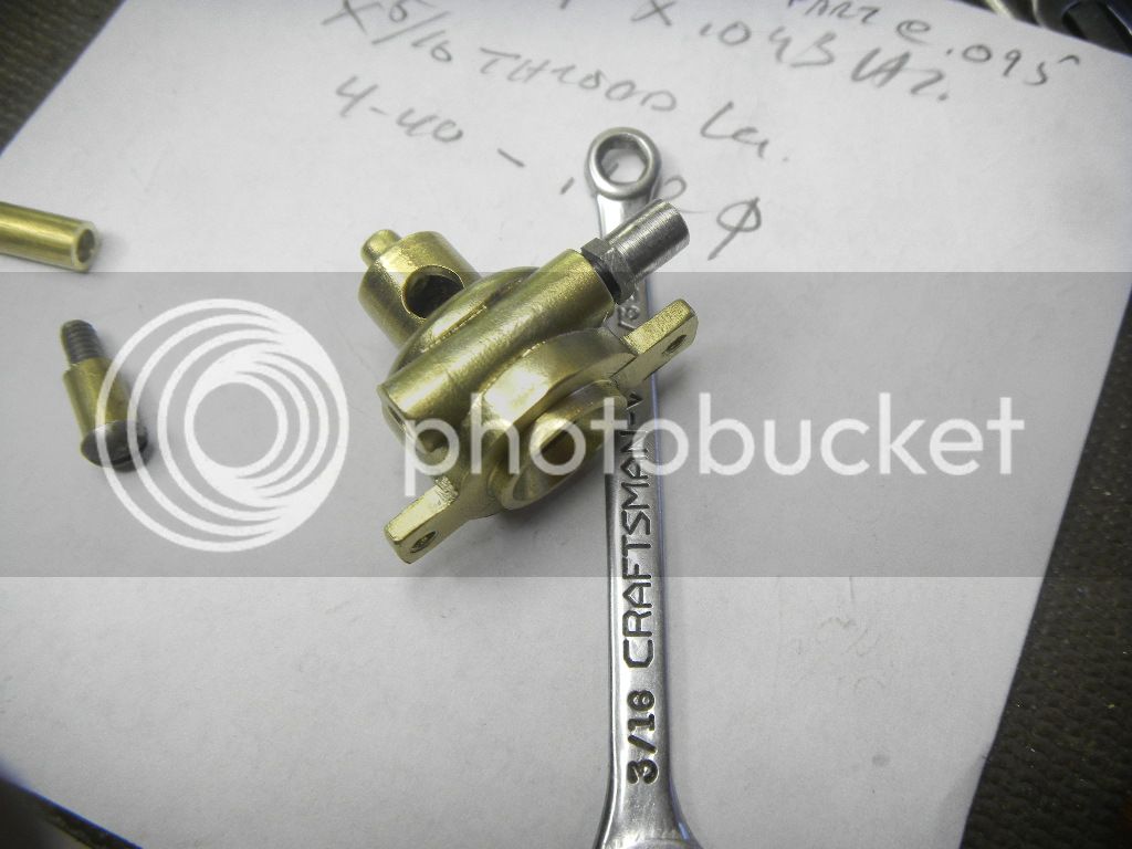
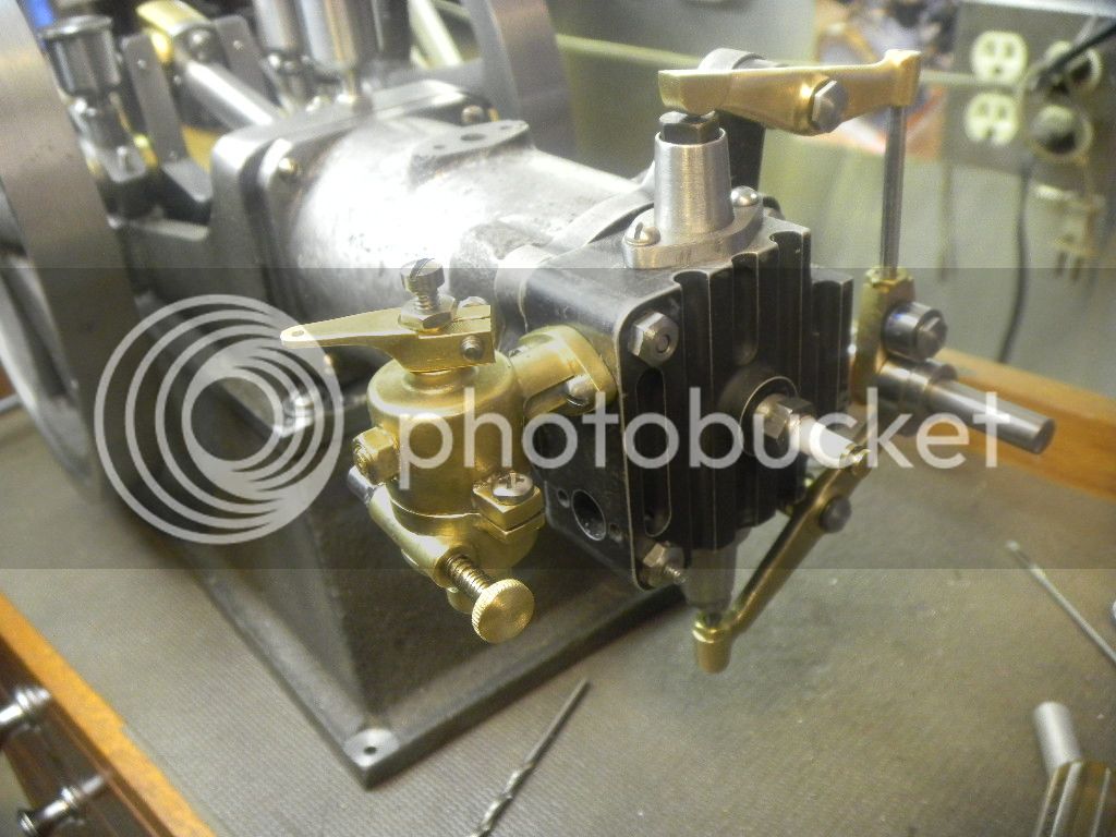
After a little tweaking this is starting to look like it might just work.

DSCN2563.jpg


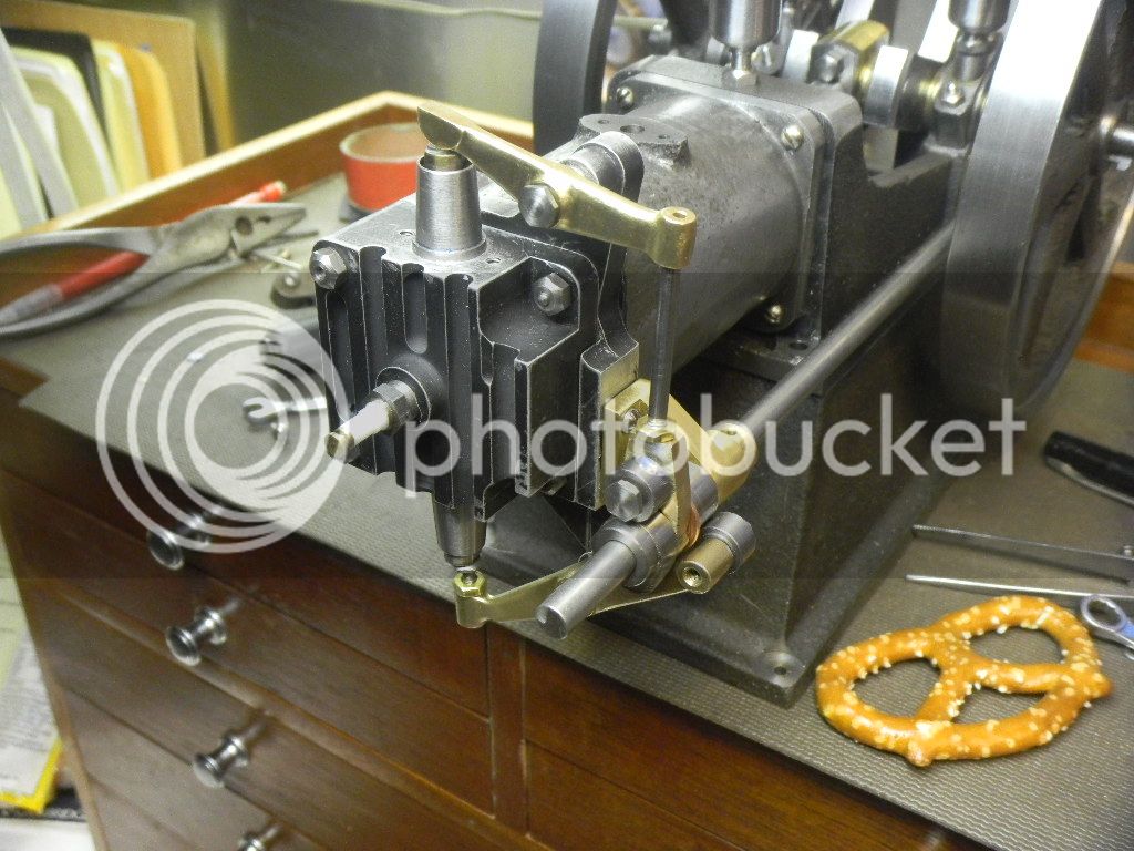
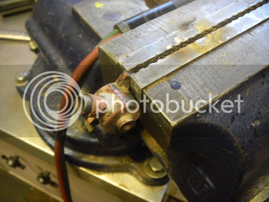
And yeah, the exhaust valve adjuster is not quite centered on the valve(just another day's lesson in the life of this amature), something else that may be addressed later on in the game.
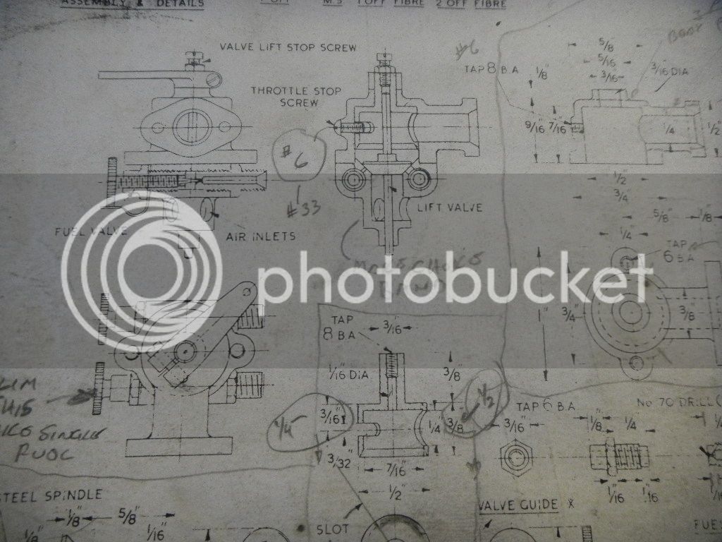
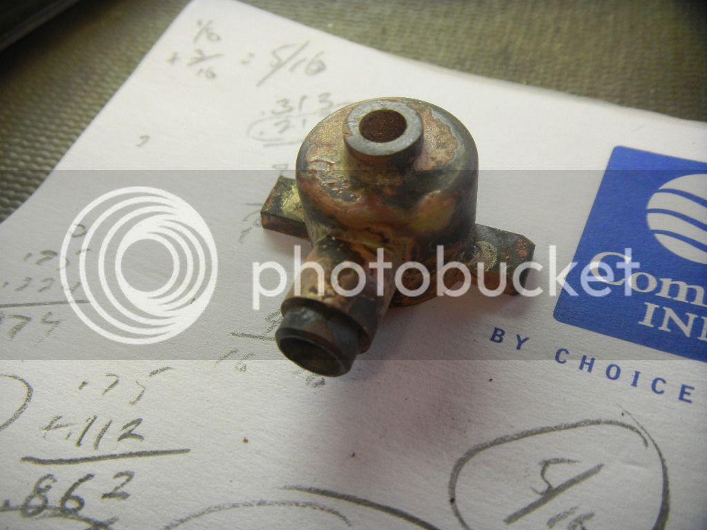
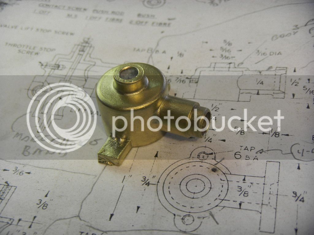
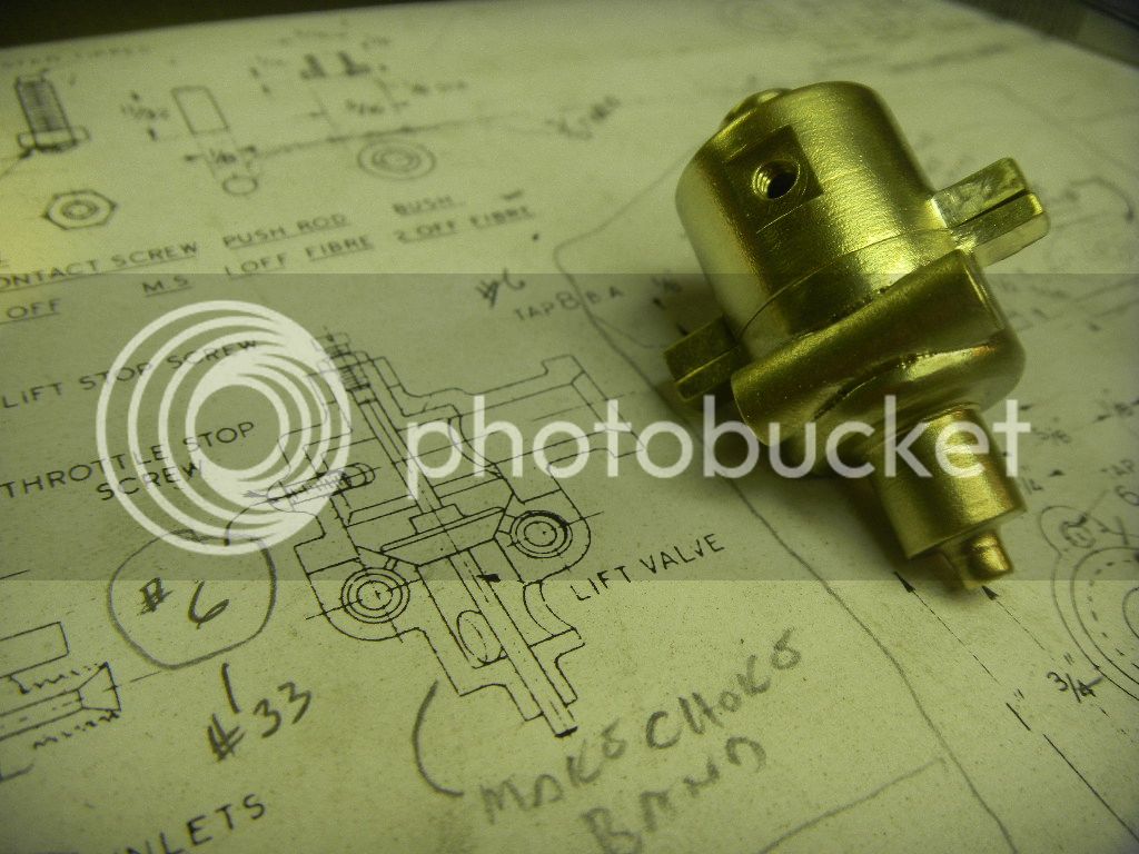
A few more small chores and I have to start brainstorming the carb, another fairly complex part coming to test me.
undecided.gif


GUS
 
Now it’s time to come up with a plan to make the carb.
Way back when I started this build, I was thinking I’d probably end up making some sort of mixer for this engine, because I had no idea how I could conjure up something this complicated.

DSCN2686_zps58ae8d00.jpg


Still not sure I thought maybe I could accomplish some of it by making weldments.
With that thought in mind, I decided to take a shot at the top housing.
Starting with a piece of of ¾“ brass bar, I made the first cuts, forming the basic shape and then parting it off.


DSCN2598_zps606d02fd.jpg


DSCN2599_zps35284541.jpg


Next the piece was rough bored to eliminate some material to make silver soldering easier, not as much mass to heat.
A slot for the mounting tabs the hold the bottom of the carb and a hole bored in the side for the flange mount.

DSCN2600_zpsea7ae391.jpg


Then a piece of ¼” x 1/8” brass bar cut for the slot and the flange tube machined and put in place.

DSCN2601_zps5d334380.jpg
 
Last edited:
Parts cleaned fluxed and gingerly balanced on the vice.

DSCN2603_zpsd303eeae.jpg


First the tab bar was soldered, then the piece grabbed by the tab and the tube soldered in.
The reason I turned it was the solder snips kept rolling off of the tube.

DSCN2604_zpsf2c51368.jpg


Soldering complete I could now finish machining the inside to finished dimensions.

DSCN2605_zps134535d3.jpg


I got so absorbed in the piece I neglected to take some pictures of the remaining machining, but it went well.

DSCN2607_zpsdaff0e79.jpg


Sand blasted and then hit with the wire wheel it’s looking pretty good.
The flange will be added later.

DSCN2608_zpsf53a7a54.jpg
 
Empowered by my success with the top half of the carb, I could now turn my attention to the more complicated bottom half.
Starting with a piece of 1“ dia brass push bar I salvaged from a demolition job ( forgot I had a piece of the ¾“ bar left), a ¼” hole was plunge cut with and end mill.

DSCN2609_zpsc16f887e.jpg


Then in the lathe the dia. cut to match the top and then parted off.

DSCN2610_zps5c53d75a.jpg


DSCN2612_zpsff2f9c84.jpg


A piece of ¼” round for the needle and seat was drilled and cut to length and inserted in the now mostly exposed hole.

DSCN2613_zpsf8d7ab07.jpg


DSCN2614_zps0ab1703a.jpg


Plan ahead!!! At this point I decided I had gone about the machining in the wrong order and started over. Working from the bottom up. That would provide a lug to hold the piece for the internal machine work.
The first piece I cut might have worked but I was thinking it would only come flying out of the chuck with that little bit of grab and I didn’t want to distort the hole I milled in.

DSCN2615_zps45e6ad45.jpg


After parting the piece off I realized I forgot to radius the bottom. So back in the chuck, the radius was gingerly cut with a rounding mill.

DSCN2617_zps6c6677f0.jpg
 
Then I milled a slot for the mounting tab and the rough assembly scrutinized and passed.

DSCN2620_zps107e9970.jpg


Then everything joined in the soldering process.

DSCN2621_zpsd8e6ecc1.jpg


Cleaned up a bit and back in the lathe the mating surface was cut smooth.
The gouge in the nearest tab was caused when the lathe tool grabbed and spun the piece in the chuck.
:mad:

DSCN2622_zps983fe0fe.jpg


Then the center rough bored and a step cut in to accept the lift valve seat which I made earlier and it was loctited in place.
The ends of the mounting tab were also turned to length in this setup.

DSCN2623_zps77b07f7a.jpg


A quick trial fit and things look great so far.

DSCN2624_zps54e75d0b.jpg


Next the valve seat was cut. The piece finish bored and a 1/16” hole drilled and reamed thru the bottom for the lift valve shaft.

DSCN2626_zps9df39702.jpg


Still in need of some solder clean up the majority of the work on the two halves now complete, they look promising.
It took about 3 days to get this far but it was well worth it.

DSCN2628_zps63aa014e.jpg


DSCN2633_zpse64fdca1.jpg


I'm posting this not too long after a large new years family dinner, pork and sauerkraut, crown roast and the works. It was great.Thm:

I think I need to get off me arse and walk around a bit.;)

Happy New Year to all.

GUS
 
Last edited:
Wow! great work on the carby Gus; I'm constantly amazed at how fast you turn out parts and how quickly the Wyvern is coming along.

Thanks for taking the time to share your progress.
Dave
 
Thanks Dave.

I was really worried that the carb was going to be a nightmare to build.

It seems the Wyvern is nearing completion, and I found myself looking at a picture of a Callahan this morning over on Smokstak, wondering if I could scratch build it.:confused:

This time of year, Oct. thru Jan is pretty much vacation time for me.
I work retail construction and work schedules are mostly ruled by what and how important the impending holiday is, Christmas rules the roost.

Add into that retail construction, for me at least, has been in the dumper since the great depression began a few years back.
Then factor in that I've decided to live out my days being semi-retired and what I end up with is a lot of time hibernating in my shop.
Just recently, my wife actually told be to get in my truck and go somewhere, anywhere, after I spent three weeks hiding out.:eek:
I have three real size engine projects in various stages of repair sitting 10 feet away but I can't seem to pull my self away from this project. It's just plain fun.:D It will be a bit of a let down when it's done.
 
Looks like there would be a high pucker factor in machining that carb!!! Excellent work. How did you get it to clean up so nice after soldering?---Brian
 
You have made a great job of the Carb a credit to your skill, having made the carb for my Wyvern from the casting kit I can say that it was a nightmare as the casting was very near to size.

Mike.
 
Hi Brian,
Thanks, Way more pucker factor trying to figure out how I was going to go at it, once I got started,I was so happy with the way it was going, I just went with the flow.
After a some years playing around making my little static models, mostly from steel ( it's the easier solder job for me) I simply sand blast all the crap off and burnish the matte finish away with a wire wheel using the bench grinder.
Way easier than polishing. If the piece was to be painted I would skip the wire wheel.

Mike, thanks. I was wondering if you had any problems with the size of the flange and the fastener clearance. I'm thinking I have some issues in this department. The flange tube is 3/8" dia. and the flange screw holes are 1/2" OC. :confused:

Also I didn't agree with a lot of the fastener sizes Mr. Westbury specified, I just used what I thought would work.

I'm not totally out of the woods with the carby yet, I still have a handful of little parts to make and then cross my fingers that the thing will actually work.

GUS
 
Last edited:
Hi Gus.
Yes I had the issue with the carb flange fixings I made my stud centres 9/16" used 3/16" across the flats nuts and reduced the tube diameter at the flange end just enough to let the nuts engage the studs and turn.

Mike.
 
Thanks Mike,
Unfortunately I didn't plan that far ahead.:p
Guess I should have stopped and did some reasearch before I started drilling..
GUS
 
The next logical step would be the throttle “drum” for lack of a better description.
It fits in the top half of the carb and involves a slot for a throttle stop screw, a hole for the fuel mix to pass thru, and a stem to turn it which also has a lift valve stop tapped into the top.
Kind of simple but I wanted to keep the tolerance of the diameter close to help eliminate air leaks.
Drilling and reaming the 1/16” shaft hole was the last process in turning.

DSCN2634.jpg


Internal parts except the lift valve now fairly complete. It seemed odd to have to order a piece of 1/16” rod as I only needed about 1 ½”, but I could find nothing else to use for it in my shop. I ’m still waiting for it and I still have to drill a fuel passage hole in the valve seat.

DSCN2635.jpg


As expected the throttle drum is fairly tight in the housing, and offers almost objectionable resistance to turning, but I think it will break in nicely.
Next in line was the throttle lever a neat little piece and fun to machine.
A sloppy little layout, just to keep me on course.

DSCN2636.jpg


Lever completed, the throttle stop screw and nut also created.

DSCN2638.jpg


It was time to make and attach the mounting flange.
To avoid the off center problems I had with the rotab, I opted to simply drill the holes and saw cut and file the shape. It only took a few minutes.

Then attaching, using silver solder. Originally I was intending to loctite the flange on, but after roughing up the area while sand blasting and scouring it with the wire wheel, I thought it safer to use heat.

DSCN2644.jpg


I used some thin alum. to make a heat shield.
I got this rig for Christmas from my wife. Every year I get the “what do you want for Christmas ?” inquisition and this year I decided to give her an opportunity to get me something I wanted besides socks and underwear and a Home Depot gift certificate.
 
DSCN2643.jpg


I got out a catalog, and circled a half dozen affordable items, dog eared the pages and hand it to her and told her to choose some or all. I got two of my selections, this was one of them.
I used it to punch the holes for the heat shields and again the next day to punch the gasket for the carb halves, works great and you an actually get a hole where you want it.

I saw this coming when I drilled the center hole in the flange. I was following the drawings and thought the clearance for the screws was a tad close, but I was already committed.

No room for the screw heads, and not much opportunity to relocate the already drilled and tapped holes in the head.
What else could I do, but gouge out some clearance with a ball end mill.

DSCN2646.jpg


This works, but I need to make some slotted screws with a bit more clearance.. It was all I could do to get these socket hex screws tightened up, and I buggered them up some even though I was using a ball end hex key.
Probably won't be much better with slotted screws.

DSCN2648.jpg


Now I have to figure out how to avoid this situation berfore I address the exhaust flange.:p:confused:
 
Last edited:
My, but you've done a lovely job on that carburetor. As far as the objectionable tightness of the throttle drum, try spreading a small bit of 400 or 600 grit carborundum paste suspended in oil on the drum and work it back and forth a bit by hand. It works miracles. Just be sure to clean it out real good with laquer thinners after the fact.
 
Thanks Brian, I'll be digging out the carborundum in a bit when I lap the valves, I'll give it a try.

GUS
 
It was all I could do to get these socket hex screws tightened up, and I buggered them up some even though I was using a ball end hex key. Now I have to figure out how to avoid this situation berfore I address the exhaust flange
Your picture reminds me of a similar access/tightening problem I had on RC engine exhaust header. Ball ended hex drivers would not engage because the angle was too steep. To solve I cut a chunk off the 'L' part of a spare allen key & ground it perfectly flat & sharp. It had just enough capscrew socket penetration beyond the curve of the allen key, maybe 1/8". Not sure if this will help your particular geometry, but it ended my stripped bolthead issue.
 
Petertha, thanks for the suggestion. I used the socket head screws because they where the only ones on hand that would somwhat work for a temporary fit up.


I had a little (maybe bigger than I think) problem with the fuel passage hole, from the needle valve to the lift valve seat.

On the drawings it is a 1/16” hole drilled square thru the angled face of the seat. That would pose no problem, but, because I floated my own boat and changed a few basic dimensions the hole now had to be started on an angle.
Being afraid of the bit running off I used my smallest spot drill (1/8”) to start and found that I accidentally exposed the dimple past the face of the seat, and am thinking it will affect the operation of the valve, letting fuel leak into the engine at even the smallest amount of throttle. Looking back, I should have started the hole with a 1/16” mill which I have.

DSCN2650.jpg


Easiest solution , I think, would be to reface the seat, but I’m thinking that will be affected by run out problems with the lathe, or may try the four jaw. As the seat is loctited in I’m thinking of trying to remove the seat and making a new one, but that process seems to have it’s own set of problems.
Am I wrong in thinking that the this little accident will adversely affect the fuel mix?

For now maybe I’ll just try to run it like that and see what happens.
Trying to keep forward motion I proceeded to the fuel inlet/jet.

I put a 3/16” hex on a piece of ¼” SS rod, using a 5C hex block in the mill, then in the lathe turned the end to accept the plastic fuel line I’ll be using (temporarily I hope I haven’t decide what to do for a permanent fuel tank yet).
Then the inlet hole drilled to a depth about a 1/16 past the start of the hex, the piece was parted off.

DSCN2661.jpg


Then reversed in the chuck the diameter reduced and threaded 5-40 as designed, using the 13/16” die holder I made the day before, it works great.

DSCN2663.jpg


Next was drilling the jet with the tiny drill bit held in a No. 1 Jacobs chuck, held in the jaws of the ½” chuck in the tailstock. The little chuck has a straight shank and I use it here or in the mill whenever I need to hold tiny drill bits.

DSCN2664.jpg


Then a seal was made from an unidentified piece of electrical insulating material.
ID punched and sandwiched in a brass mandrel and turned to dia.

DSCN2665.jpg


DSCN2668.jpg


DSCN2670.jpg


Only a couple more parts and the carb will be complete.

I'm starting to wonder where that 1/16" rod I ordered got to.:confused:
 
Then the needle.
In the past I’ve used a sewing needle inserted in the end of a screw and used a separate disc loctited to the end of the screw.
Kind of iffy trying to drill a little bitty hole on the end of a little bitty screw and hoping it will be concentric.
This time I’m going to try turning the whole thing as per the plans.
Reducing the brass round in little steps worked really nice.

DSCN2679.jpg


Then a little it of an oopsie when I got carried away turning the smaller ID of the point.
Not sure if I would have enough thread left on the piece, I forged ahead and treaded it anyway.

DSCN2681.jpg


Then knurled the head and parted it.

DSCN2682.jpg


All finished it had enough thread to close the needle, but I wasn’t sure if I would have enough for adjustment, so I put it in the jar of shame and made another, which came out great.

DSCN2683.jpg


HMMM, still wondering where that 1/16" rod got to:confused:
 
Nice Carby
Top job Mate
Pete
 
Gus. The carb valve seat, I had a similar problem as yours what I did I put the plain end of the drill into the hole having put a bit of wax (release agent ) on the shank, then I made up the groove with a bit of JB Weld, when set withdraw the drill and you are left with a nice hole where it shoud be, and I then re- seated the valve with a bit of grinding paste, upto now the carb is performing OK.

I think if you leave it as it is you may get a bit of fuel leakage.

Mike.
 

Latest posts

Back
Top