Wyvernish Build

Home Model Engine Machinist Forum

Help Support Home Model Engine Machinist Forum:

This site may earn a commission from merchant affiliate links, including eBay, Amazon, and others.
Well, I thought I had the valve body seal decision made, but thanks to Mike I’ve got a better way.
I never thought to check metric O-ring sizes.


I try to avoid the metric thing, although I wish they had gone thru with it way back in the 70s? when it was a big debate in this country.
It’s a much easier system but we steadfastly refused to accept it and chose to maintain our archaic system of measurement.
There is no reason that I should need two sets of wrenches to work on my vehicle or have to have a decimal equivalent chart hanging in my shop.
A lot more important things in this country should be maintained, but our measuring system should have been allowed to fade into history.
Sorry, I had to get that off my chest.

I did find a 1mm size that will work for the bottom seal without any changes and I can dump the Teflon thing.
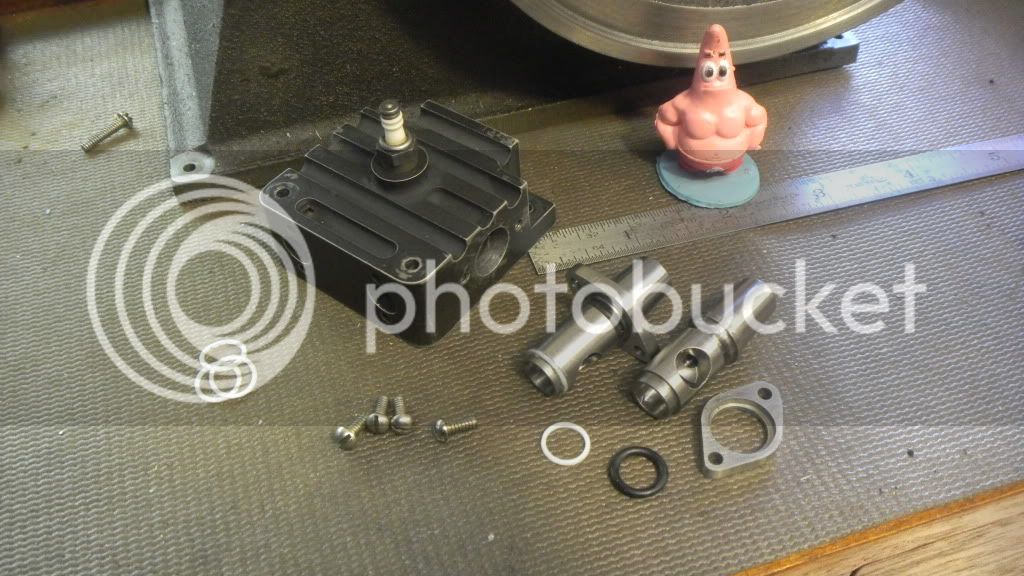
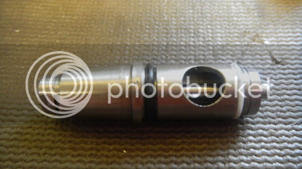
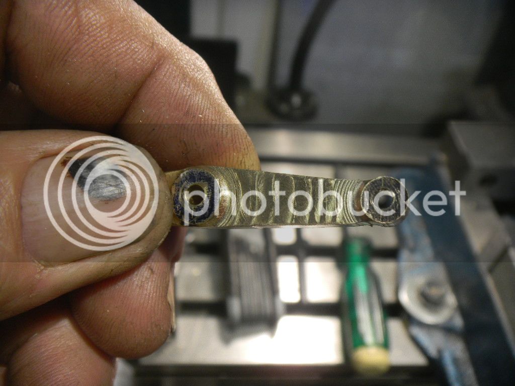
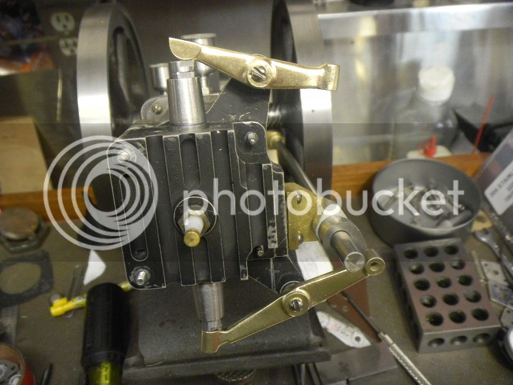
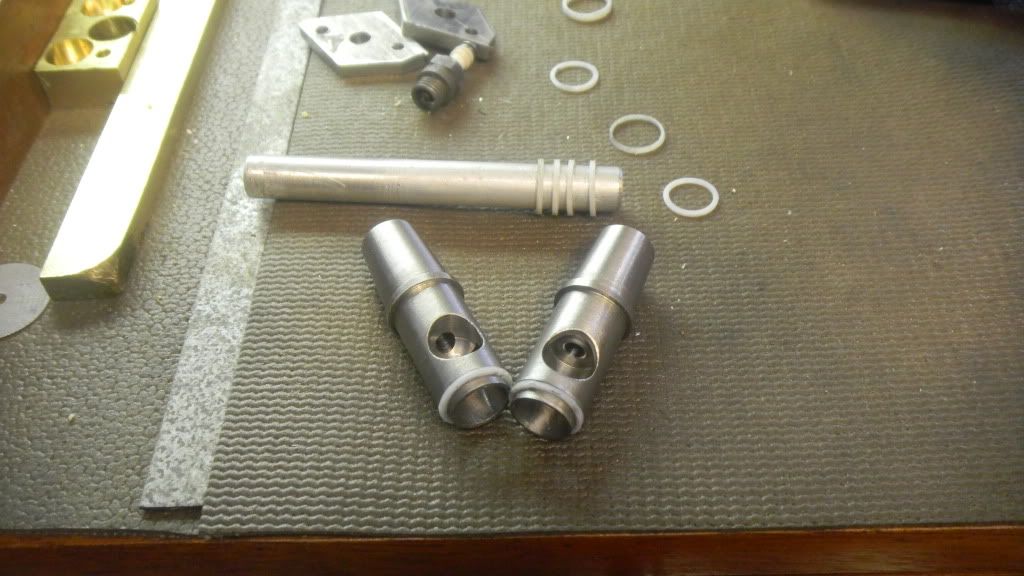
Having settled on how to seal the valve bodies it is/was time to build them.

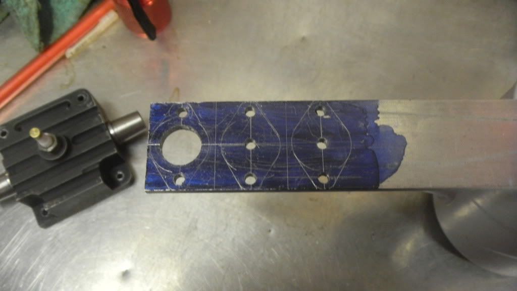
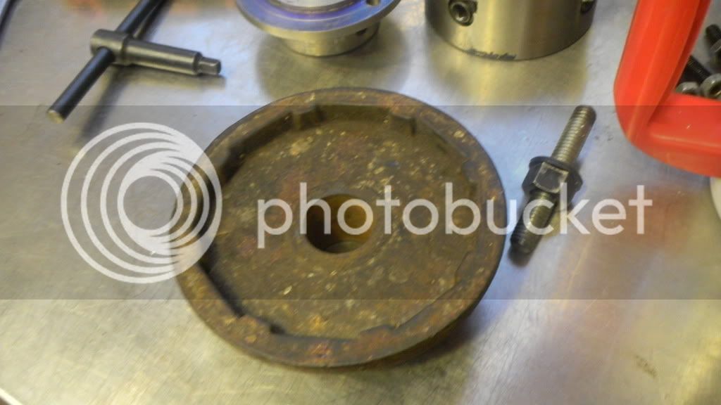
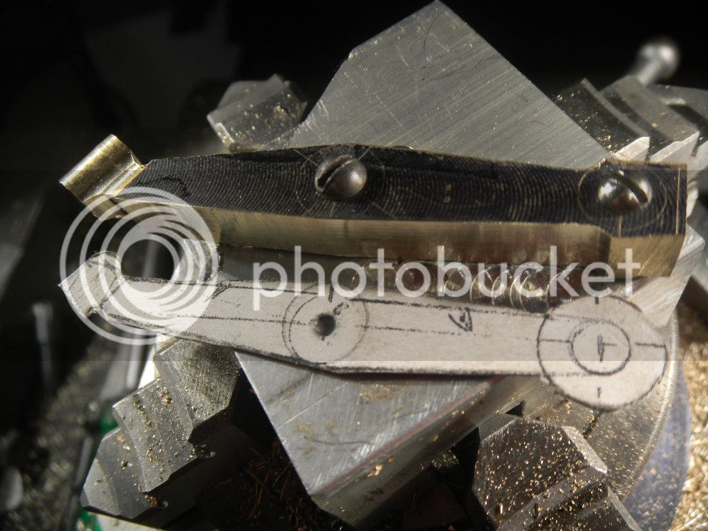
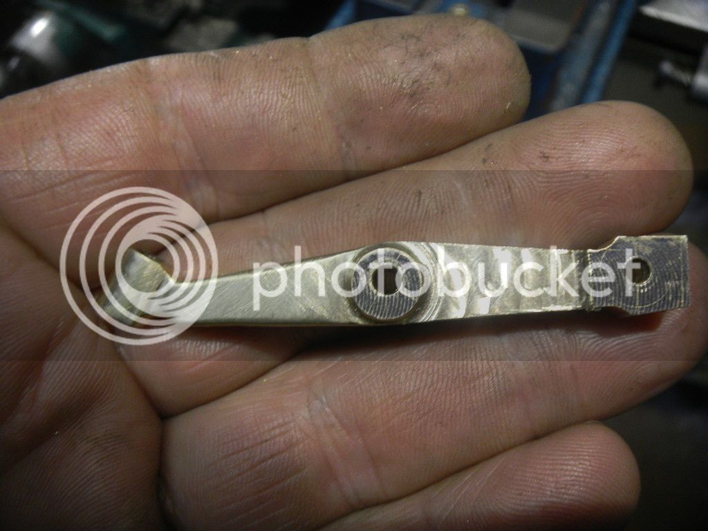
Still sticking with a separate flange I decided to make it a clamping type with a step in the flange to engage a ring left on the OD of the body.
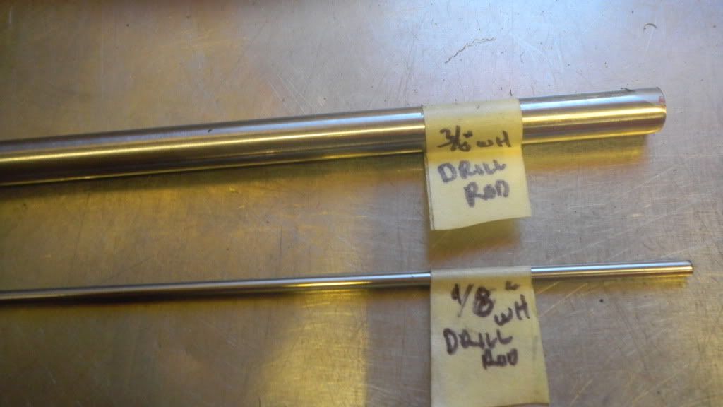
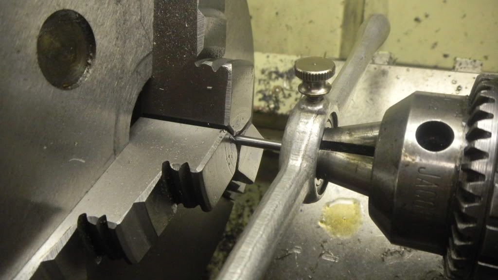
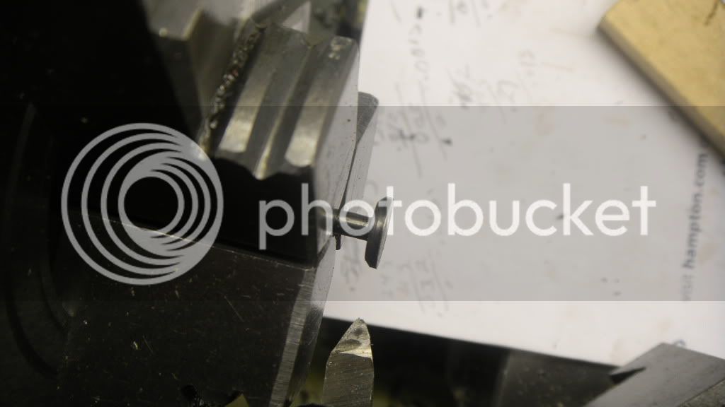
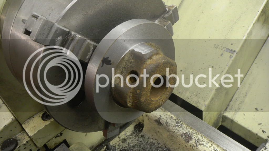
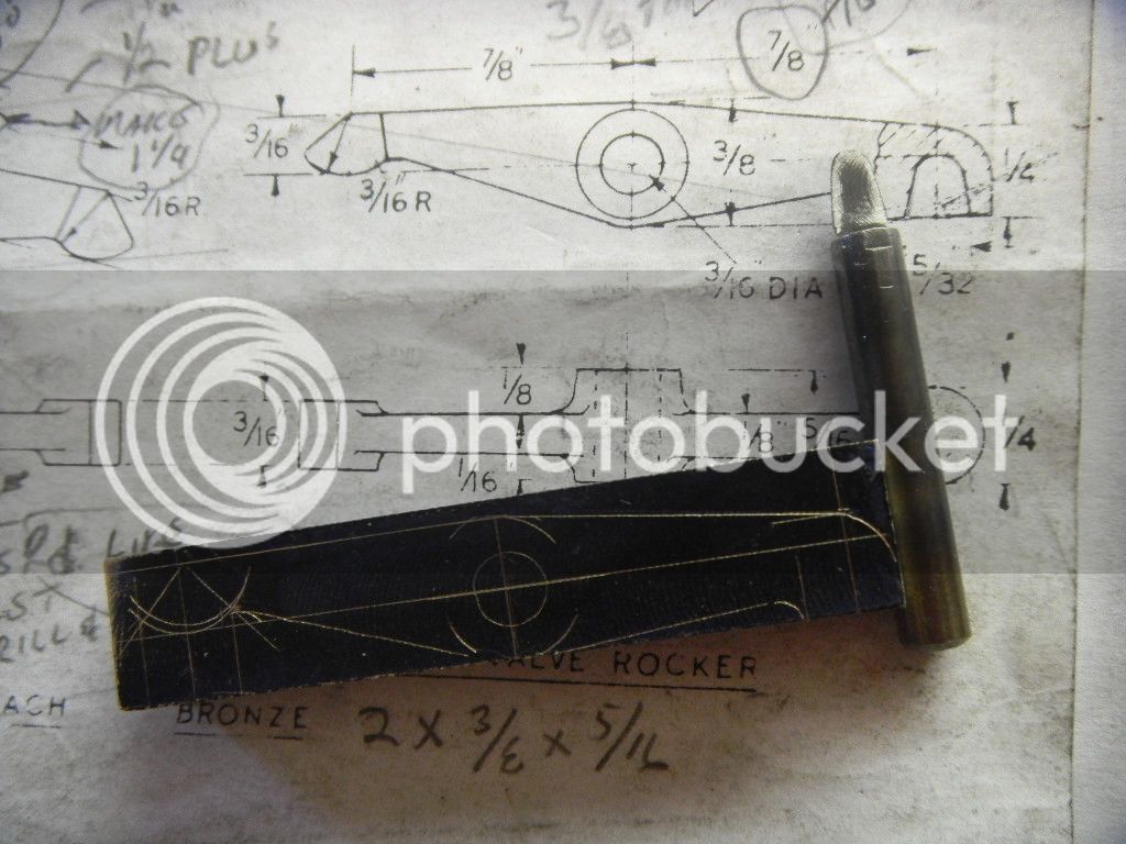
With a ½” SS bar in the lathe starting on the bottom end (or top, depending on which valve body your looking at) I cut the 7/16” OD and the 3/8” in OD step for the inner seal at the end.

DSCN2363.jpg


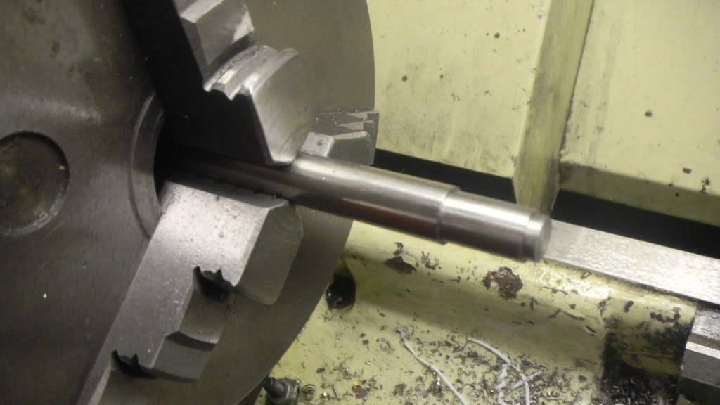
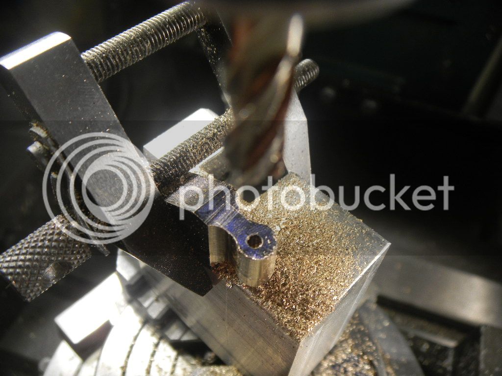
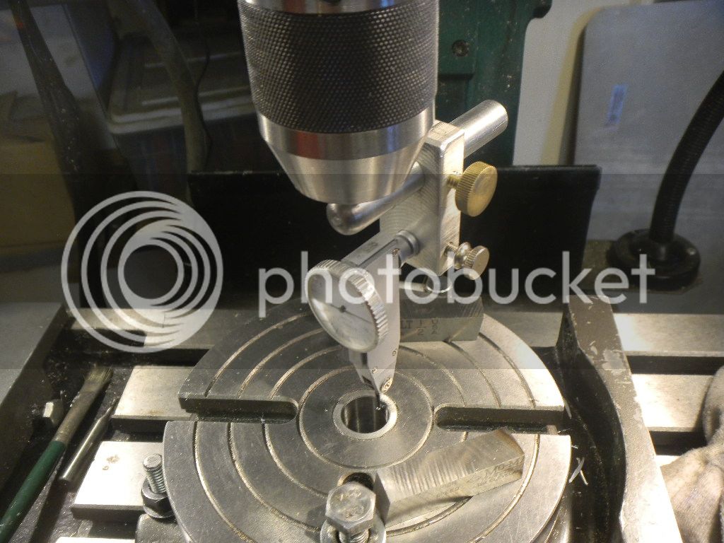
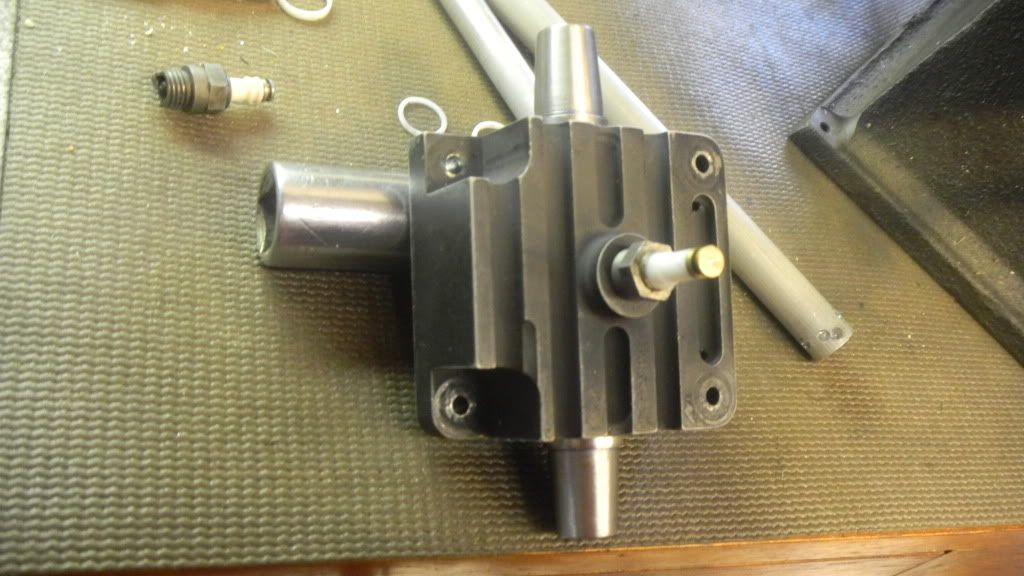
At that point I decided to test the fit in the head and while at it I traced the location of the port.
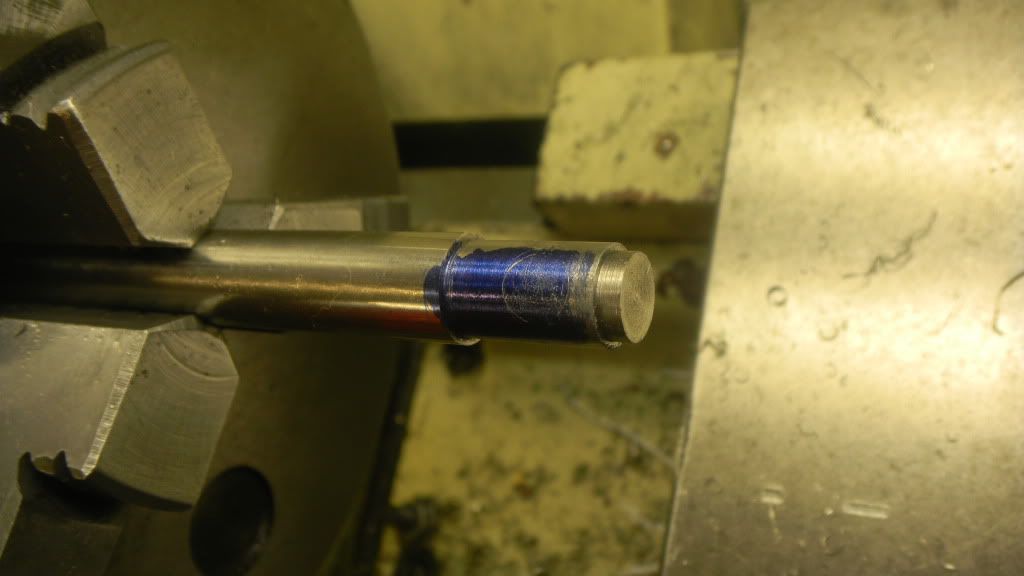
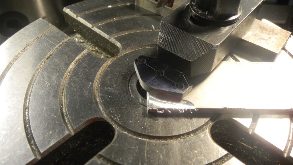
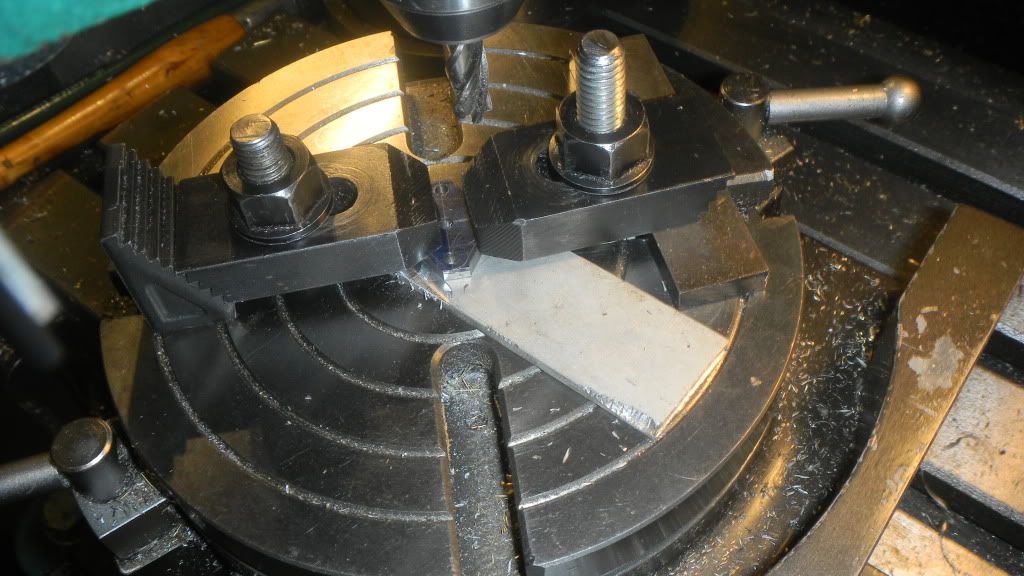
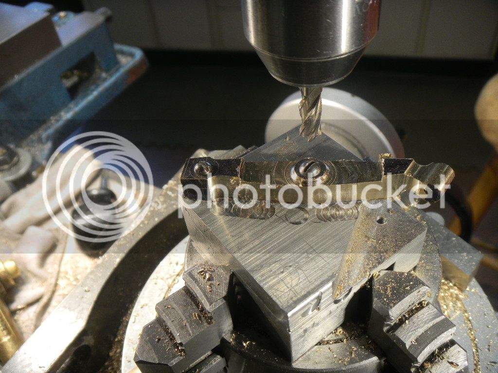
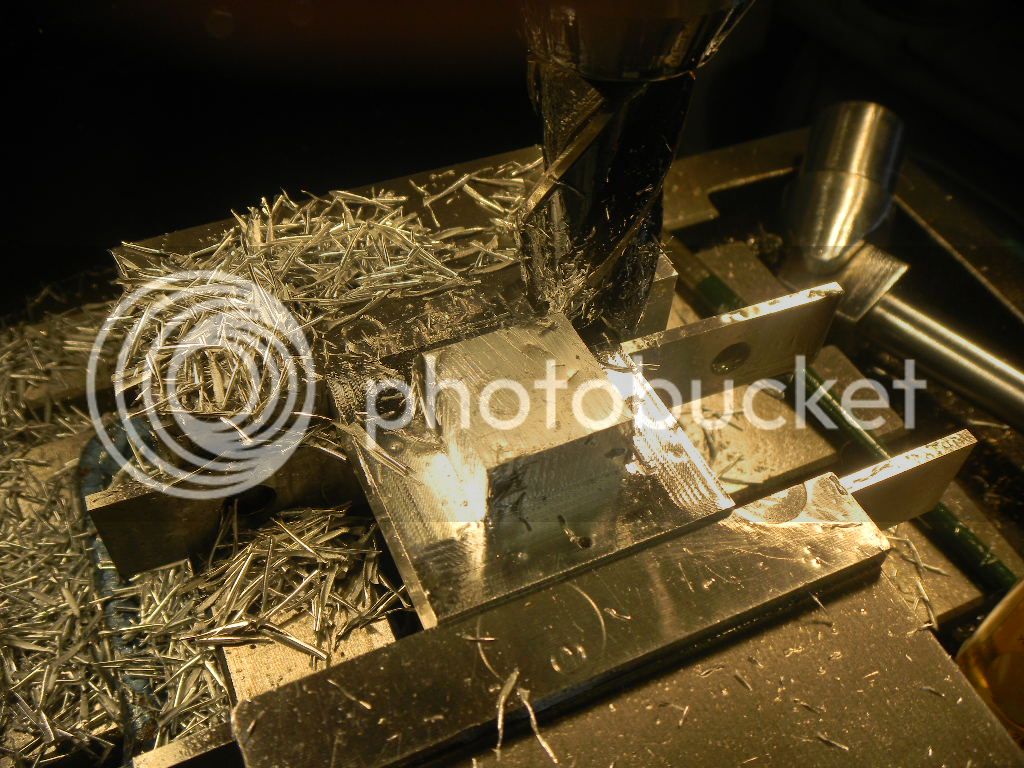
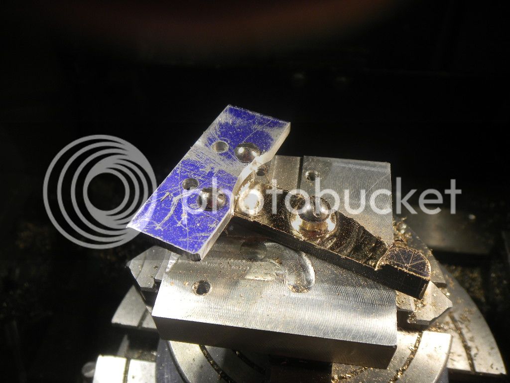
DSCN2369.jpg


A 1/8” dia hole was drilled and reamed thru for the valve stem and then the bottom hollowed out to the top of the port location. The body was parted off and in the mill the port holes where bored with an end mill.
Sorry, no pics, my camera battery needed charging.
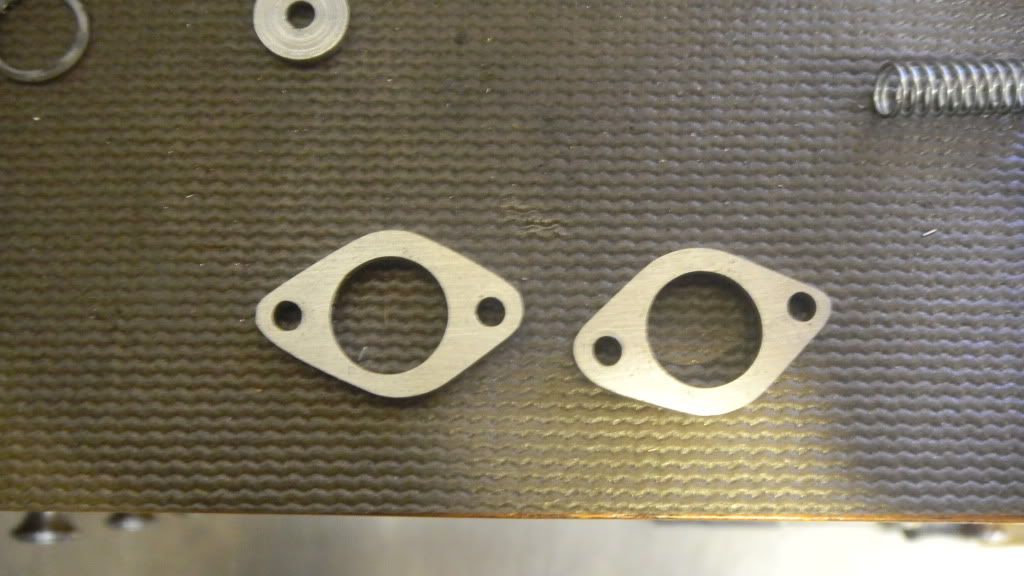
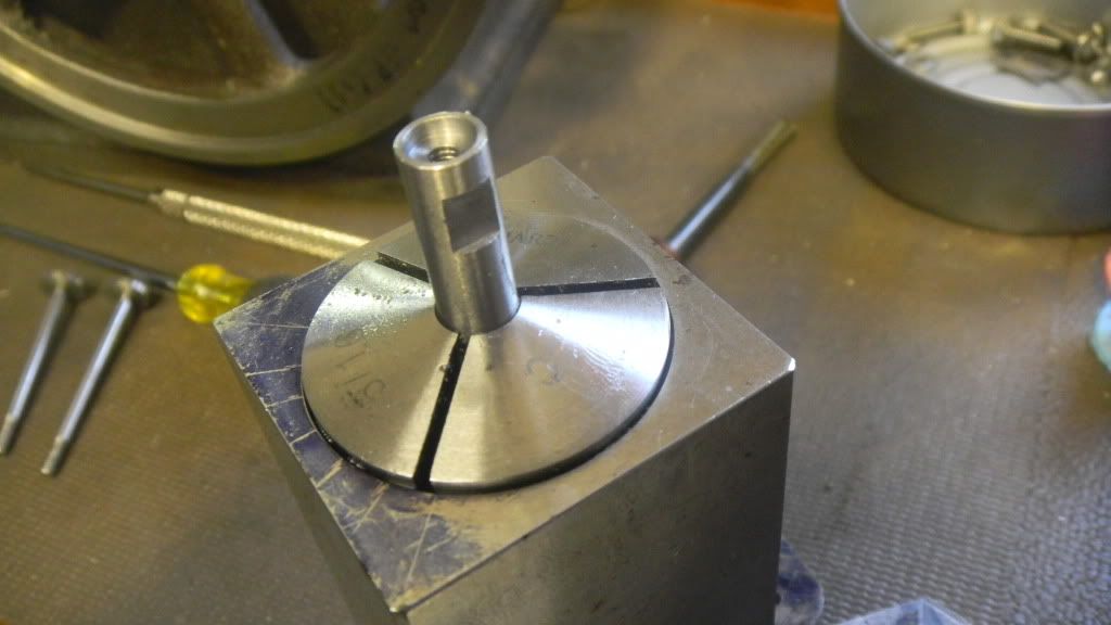
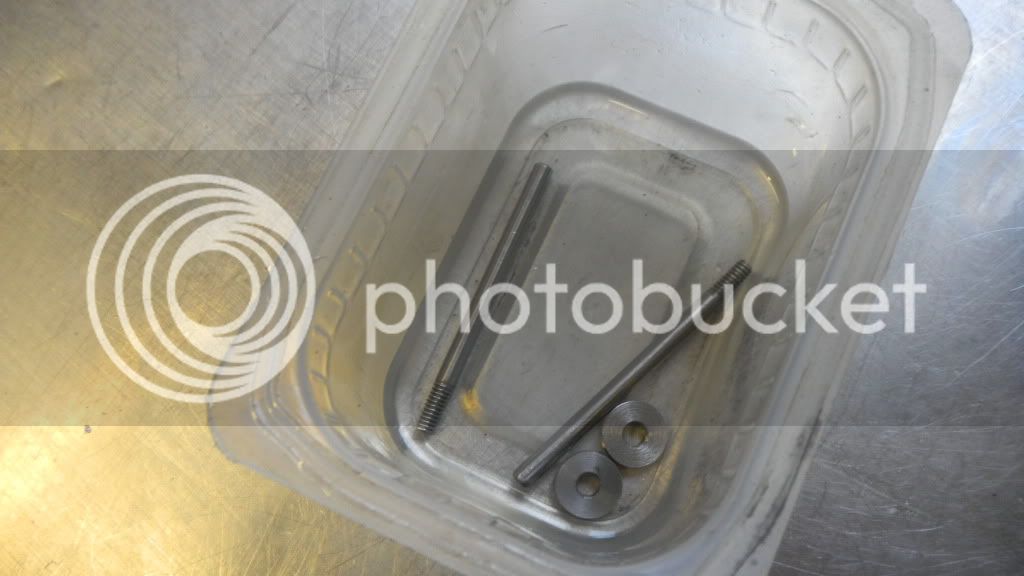
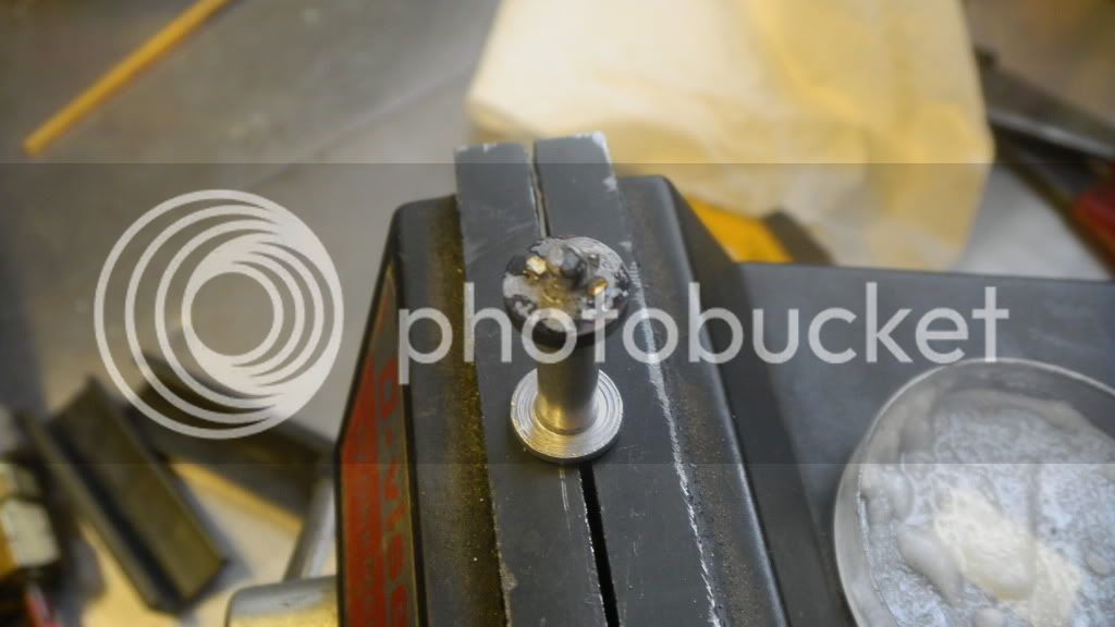
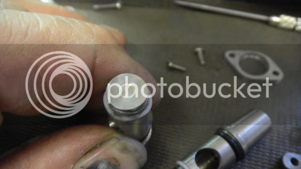
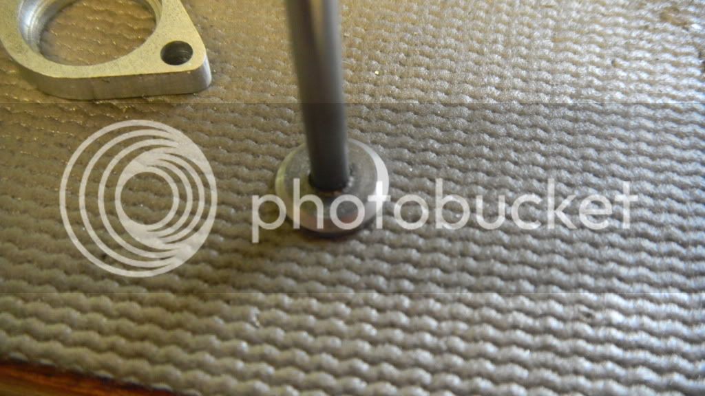
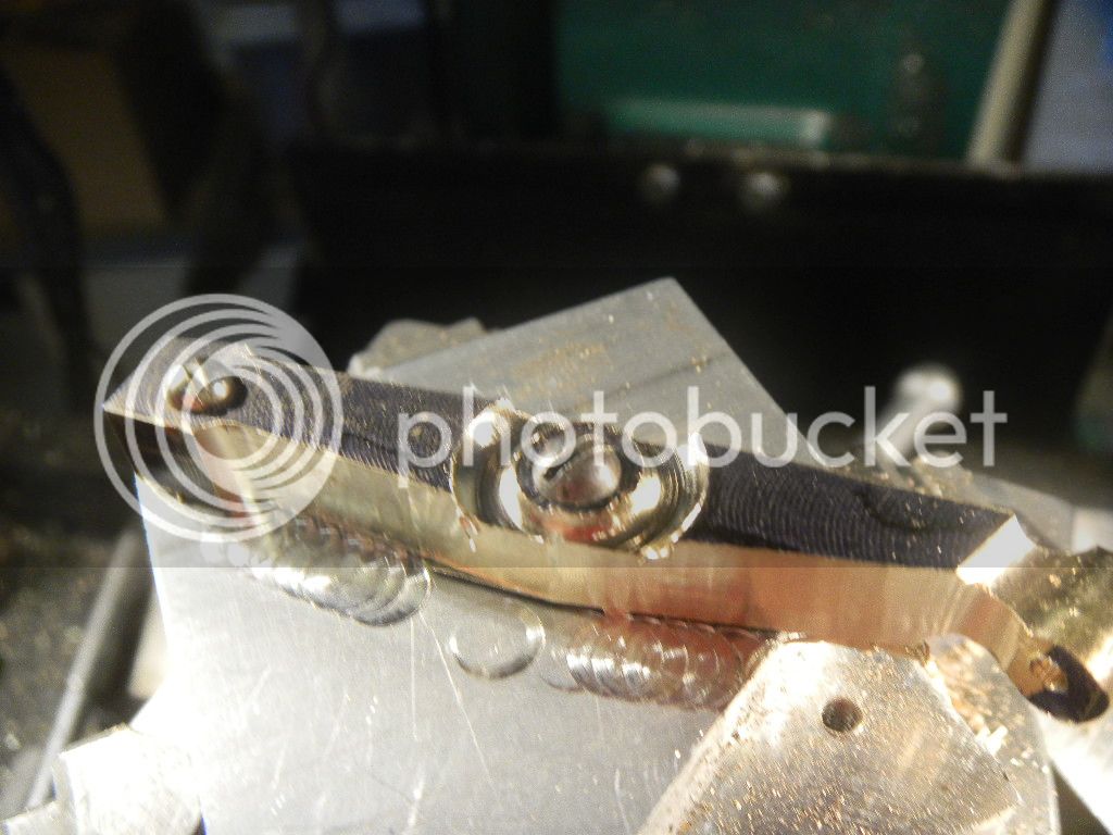
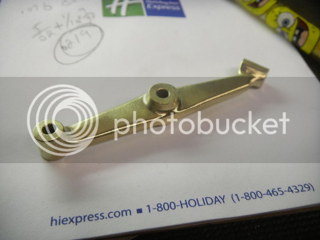
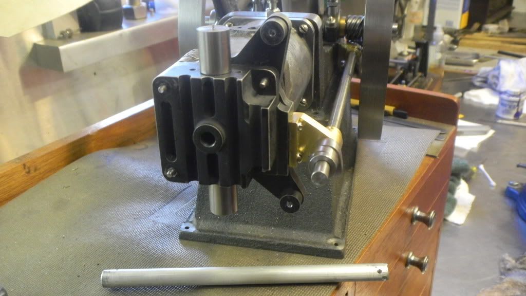
Now semi complete another test fit.

DSCN2370.jpg


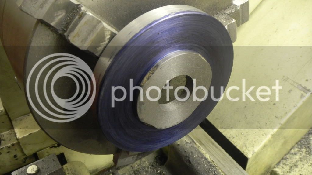
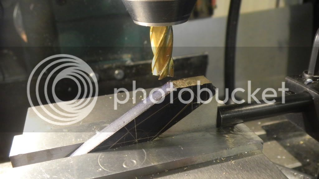
Then back in the lathe the top ends were hollowed out with a drill and finished flat at the bottom to accommodate the valve springs.
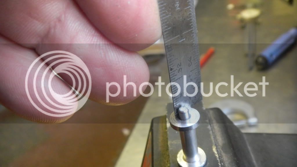
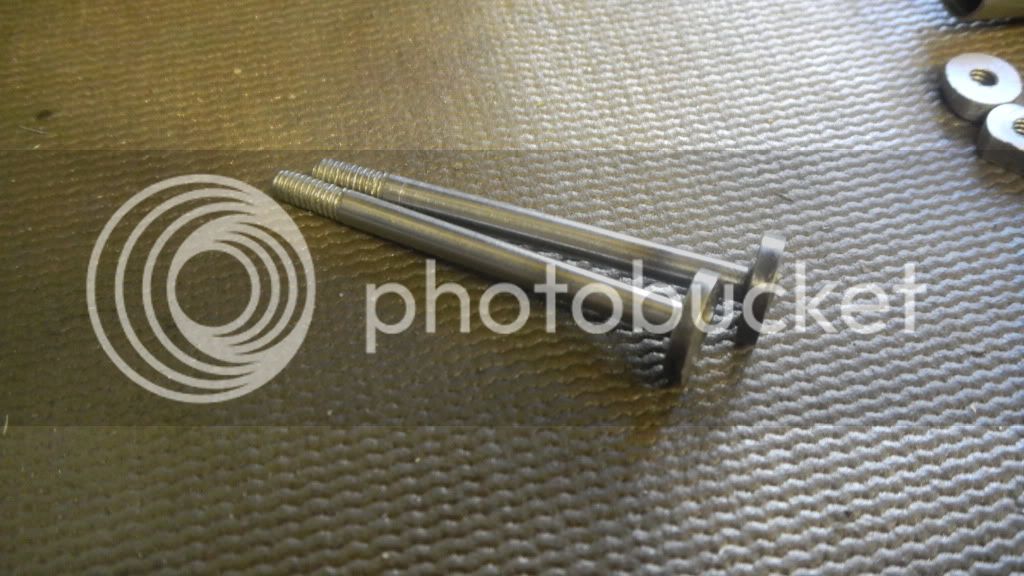
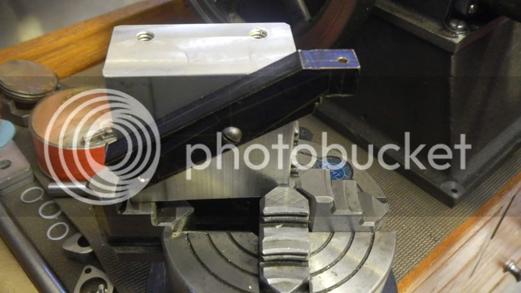
Also the taper was cut by trial and error. I measured a 3 degree angle on my sketch, but I snuck up on it anyway. Just being careful, not wanting to ruin them at this point.
This time I just plain forgot to take pictures of those steps.

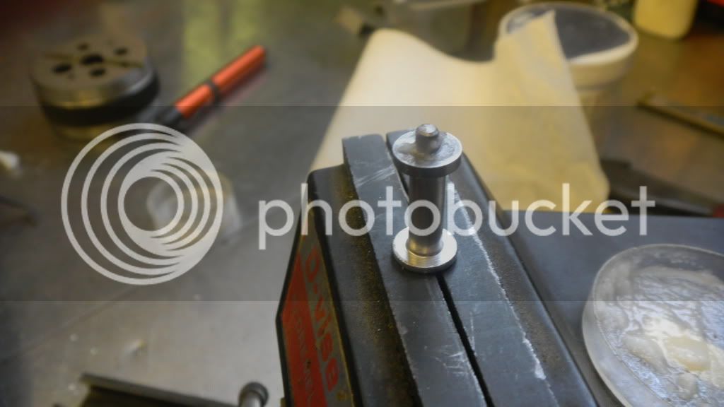
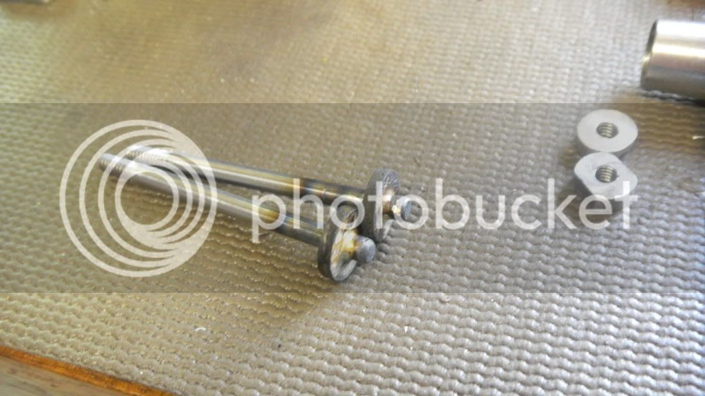
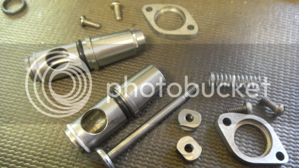
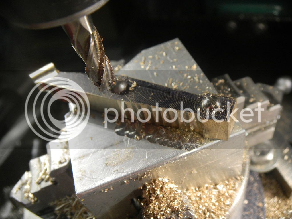
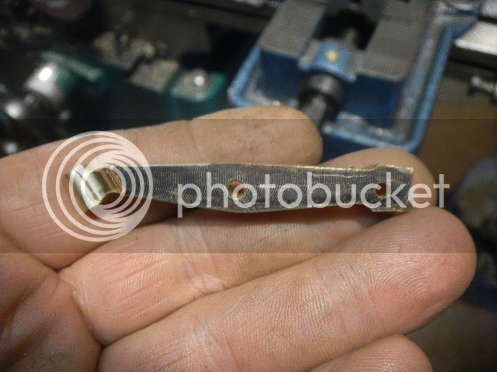
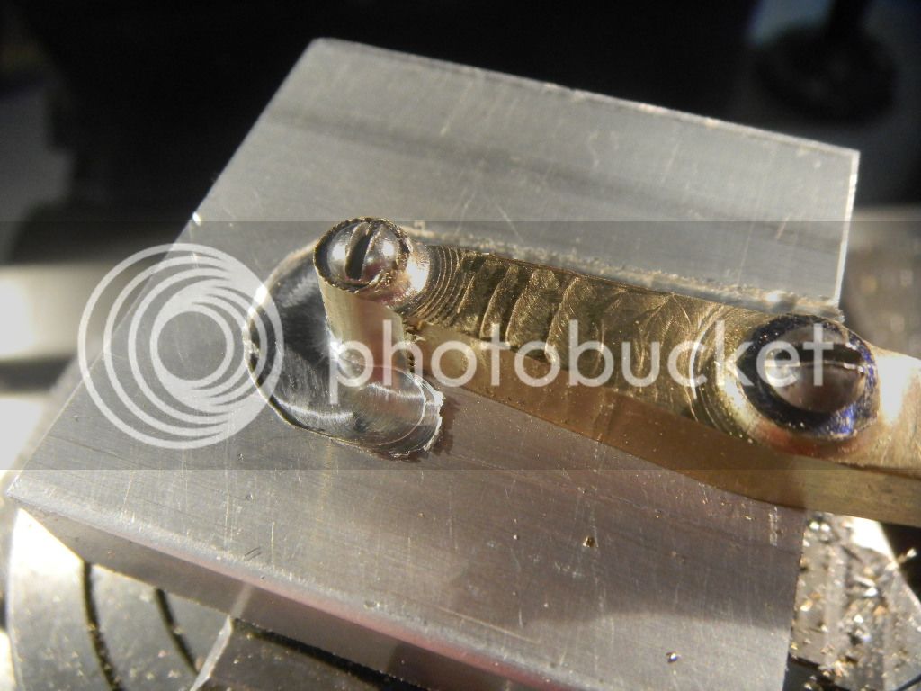
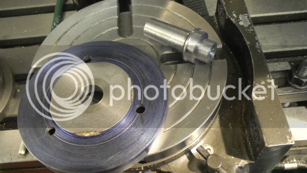
First part almost complete, just noticed I didn't cut the grooves for the top O-ring.:eek:

DSCN2378.jpg
DSCN2377.jpg
 
Nice progress Gus! I appreciate you taking the time to explain your trials and tribulations and how you over come them.

Pat
 
Gus. Nice to hear you found Metric O-rings, I like the separate flange idea for the valve cages, I never thought of that method.

I am finding your build very interesting and getting some good info, keep up the good work.

Mike.
 
Here in Australia we adopted the metric system a long time ago, yet O-rings seems to be the one exception. I used to sell them by the thousands when I worked in bearing sales and I would say at least 98% are still imperial (BS numbering). But I have to say, working in mm is a heck of a lot easier than inches.
 
Guys, thanks for the replies.
I guess at least some of us, who are posting our builds, occasionally get the feeling that we are alone in the vacuum of the internet, putting our days toils into words and pictures.
I have to say, posting my build requires almost as much time as the build itself, but both give me a lot of enjoyment
It is a good feeling when you here/see another voice making coment or giving you an attaboy.:):)

GUS
 
Then on to the flanges.
After laying out the two flanges on the newly arrived piece of 1x 1/8 hot rolled, annealed 303 SS. I went to the mill and sarted the drilling operations.
Then I got carried away and drilled the 7/16” dia. center hole, completely forgetting I wanted to use the pilot hole for centering while I was cutting the radii.
No problem at this point, just another ¾” of the stainless bar.

DSCN2382.jpg


Then on to the RT for the radii.

DSCN2383.jpg

DSCN2385.jpg


Although it worked, the centers were off some and the flanges look a little lopsided.
But, I went ahead and drilled the center hole and milled a step in in the hole.

DSCN2412.jpg


I’ve decided that the way I did this would have been much easier with a fixture clamped in a 4 jaw chuck on the RT and with the pieces fastened thru the mounting holes. The flanges don’t look that bad when they are on the valve bodies but I’m thinking I will probably redo them, maybe.:rolleyes:

I still have more flanges to make so I will make a new back plate for my little 4 jaw and mount it on the RT at a later date (when I feel like it).

In this picture they have the O-rings and trial Teflon seals installed. I’m thinking these will work just fine, but I’m going to order the metric O-rings, I think they will be more user friendly.

DSCN2391.jpg


I still have to make the valves and cut the valve seats.

GUS
 
Hi Gus

I haven't commented on your build for a while; but I wanted to know I'm still here following along. The engine is coming along nicely and you seem to be on a roll with making parts!

I may have missed it but I was wondering about the 2 piece head; is this the way the original was constructed?


Your work on the valve chests is also great!
keep plugging along.


Dave
 
Dave, thanks for checking in.
I've been eagerly watching and waiting for new posts on your build in the Engines From Castings section. That Pacific Vapor Engine is some different from ordinary and, as usual, your work is impecable.
Sorry to hear you lost your pictures.


The original head is a one piece alum casting, and I've read that a cast iron head is/was available.

I chose to make it the head two piece because it was much easier for me to build from scratch.
I find I'm having some:rolleyes: difficulty trying to figure out how to make (machine) some of the casting shapes from bar stock.

I keep going back to the way of thinking that some of these shapes could be more easily built, by me, as weldments, using the same parts that would have been glue ups of the wooden casting patterns.
BUT, I'm trying to learn how to use this machinery, which has opened up an entirely new world for me.

I've got the rockers laid out on some brass barstock for a couple of weeks and am agonizing about how I'm going to go about the machining operations. I guess it's time to pull out the stops and turn the machinery on. I'll post the results.

GUS
 
Time to make the valves.
For the first time during this build, I finally feel like I know what I’m doing.
Not just because I’ve made valves before, but because I can handle the silver solder thing fairly well IMHO.

I first started using silver solder a lot of years ago when I went into my silver jewelry making period.
Then got a lot more experience when I went into my modeling era.

Note: To me an period in my life lasts for, maybe, a year to five years.
An era last for much longer. I’m still at it after 20 years or so, maybe 30.
Model engine building is the latest phase of this era.


My material of choice this time is drill rod. Usually I would choose SS, but I don’t have a piece of 1/8”SS rod on hand.

DSCN2393.jpg


I’ve read that some people have experienced some problems from rust do to condensation, but I’ll take a chance.

First operation for these valves is to thread the end of the valve stem for the valve keepers.
I don’t like Mr Westbury’s version of the valve keepers but, I’ll expand on that in a bit.
I don’t have any tailpiece die holders, so I use the jaws of the chuck to keep the die squared up. Works for me.

DSCN2399.jpg


DSCN2401.jpg


My finger is in the picture because my camera (Nikon Coolpix) seems to have trouble focusing on small objects.

I went right on to making the 5/16” dia. two piece keepers.
What I don’t like about the design is that these keepers are intended to be tightened against each other to lock them on the threaded valve stem. All well and good, but, there is a problem with that.

The design of the valve cage almost or entirely covers/hides the lower keeper. No way to hold it to tighten or loosen. And if you did manage to get the two pieces locked up tight you may not be able to loosen them. But I went on and made them anyway with a small modification.
I would put small flats on each piece so I could use wrenches to tighten or loosen them.

In the lathe I put a recess a 5/16” dia rod with a ¼” end mill and then drilled and tapped the hole for the stem.
Then used a 5c square collet block in the mill vise to put opposite flats in the bar at the appropiate dimension to form one of the mating keepers.
I cut the flats large enough to accommodate both pieces.

DSCN2410.jpg


The first piece parted off in the lathe and then the remaining piece still in the chuck was stepped down to fit the recess in the end of the first piece and also parted off.
This is the temporary assembly. I will keep the the lower keeper exposed enough to get a thin wrench on it.
The punch marks on the clamping ring are to index the port to the head, so I won't have to guess if I pull the cages after the engine is assembled.

DSCN2414.jpg


Mike, if your reading this, I’d like to know how you approached the valve keepers on your Wyvern. On all of the pictures if Wyvern engines I could find, it seems that the builders used a number of different methods.
 
Next operation will be to silver solder the stems and heads together.
 
 
Gus,

I made a loose keeper which slides on the valve stem and is held in place with a home-made circlip in a groove in the valve stem, the keeper is a sliding fit in the valve cage spring housing.

The keeper is recessed for circlip, and a shoulder for the spring, hope the pictures help.

Mike.

Spring Collet 1.JPG


Valve Keeper.JPG


Spring Collet.JPG
 
Mike, thanks for the pics of your method, I may just go and make new valves or maybe think up a way to modify these.


This is my mini acetylene torch. I’ve had it since the silver jewelry period. It’s my go to when I need to silver solder small stuff. (Actually, smaller stuff has been 99 percent of my silver soldering experience.) It’s capable of a very tiny flame (almost pencil point) for real small stuff yet it will produce a surprisingly large flame. It has several different size tips but the one on it is the only one I use.

DSCN2415.jpg


This is my acetylene hose. :eek: Good grief, after many years of service, I guess it’s time for a new set of hoses. I’ve had a few gas leaks catch fire over the years mostly from a loose fitting and it usually happens when I’ve got the dark glasses on, but you can feel the heat. Not funny when it happens. I can imagine a broken hose would be pretty scary.


DSCN2416.jpg


This is the flux I’m currently using, I bought it om EBay a few years back.
I’m not real fussy about the flux, everything I’ve ever tried seems to work well.

DSCN2417.jpg


And last but not least, the silver solder, also an Ebay purchase. I didn’t see the clear tape on the container and broke the cover when I tried to pry it open.

DSCN2421.jpg


The solder cut into small snipits. The little squares you see are the last of the sheet solder I have left over from the jewelry thing.
The white stuff is flux. I keep the solder snips in this little plastic container.

DSCN2419.jpg


I always mix the flux and water in the lid. The amount of water to use isn’t critical, I like a thin paste.

DSCN2420.jpg


About a nano second after I took that picture I knocked the snipit container off the counter and all was lost in in the long distance swarf from the milling machine.
I usually keep the floor swept better because it’s easier to find dropped screws, etc., but this time…
More snipits, easy to come by.

DSCN2422.jpg
 
Now to the actual soldering.
First the parts are given a bath in solvent (acetone in this case).

DSCN2423.jpg


With the valve stem in the v-groove of my Dremel vise, I used a sex bolt for a spacer (it was handy) and it also served to help make sure the valve head was square to the stem, it’s sliding fit. The length was also adjusted in this setup.

DSCN2424.jpg


Flux paste applied…

DSCN2425.jpg


And the fire lit.

DSCN2426.jpg

DSCN2428.jpg


And heat applied until the flux dries and melts in.
Then the snipits placed as close to the stem as possible.
If you try to place the snipits in the flux paste before melting the flux, they will usually dance around in the steam and fall off of the work piece.

DSCN2429.jpg


Then the heat is applied again, very lighty at first so the flux remelts and helps hold the snipits in place. The force of the flame can easily blow them away.
Keeping the flame moving so as not to overheat until the solder liquefies and hopefully runs into the joint. It will usually follow the flux, but every once in a while if the prep wasn’t right or things get too hot, it will go every but where you want it.
This time it flowed perfectly.

DSCN2435.jpg


You can see my reluctance to solder, as this mess now needs to be cleaned up. Easy on these valves, but on a more complicated piece it can be pretty difficult.
I’ll add that I tried Loctite for the valves on my little H. Ford engine. The exhaust valve let go on the first hot run but the intake valve is still going strong after a lot of runs. I think the Loctite would have held up on my Little Brother, which runs very cool.
Cleaned up with the wire wheel and some of the excess length hacksawed off.

DSCN2436.jpg


Then to the lathe to be gently faced and the seats cut.

DSCN2437.jpg


You can see how the solder filled in the shallow chamfer and how it migrated to the uderside.

DSCN2440.jpg

DSCN2441.jpg


Valve cages and valves complete except for cutting and lapping the seats and I still don’t like the keepers.
I just looked back at the dates on the pics of the valve cages, about 3 weeks of spare time involved.
Later in the build I’ll make a valve seat cutter, using George Britnells plan. I made a smaller cutter for my other two engines and it worked good.

DSCN2439.jpg
 
Thanks for the realliy good silver soldering & pictures & description. This is on my 'list of skills to acquire'.
- can you elaborate on the %silver/whatever composition of the solver solder you used
- Im also interested to know what size/type of ocy/acetylene tanks you use. I'm looking at a little bit larger torch (a Meco) 'one day'. That one you show seems pretty handy for smaller size stuff.
 
Petertha,
Glad you like the silver soldering, I'm certainly not an expert, but I can get the job done.

This is the spec sheet fo the solder I'm using currently, the highlighted 50N.

DSCN2504.jpg


A lot to choose from. Melting temp. is one consideration. If your soldering brass, silver you need to choose a melting point somewhat lower than the item your soldering, also in cases like silver you would want an alloy that comes in close to the color IE, higher silver content, but also costs more.
The container shown only cost $10 plus shipping and will probably last me the rest of my life.

As for torches, you can get an average sized torch and use different tip sizes to accomodate your heat requirements.
These are my tanks, I don't actually know what size you would call them, but they are fairly portable, I can still lean them on the tailgate and slide them up into the bed of my truck if needed.

You may just notice that I put a new set of HF hoses on them.

DSCN2507.jpg


"Choose wisely my freind."
 
It’s time to make the rockers, there two on this engine and of course they are different from each other.

I decided a while back that at least some of the work had to be done on my rotary table, but I would have to find a better way to hold the parts.

Quote from me on my post #66:
“I’ve decided that the way I did this would have been much easier with a fixture clamped in a 4 jaw chuck on the RT and with the pieces fastened thru the mounting holes.”

I’m going to give that a shot, but first I have to get the little four jaw mounted on the table. So I have to make a new mount for it. Currently I have a mount on it that I can hold it in the bigger 3 jaw on my lathe.


DSCN2458.jpg


No way I'm going to spring the cash for the material, I'll have to make it from something I have on hand.
I made a thorough search of my shop and found two candidates with the proper qualifications. The rusty cast iron adapter of some kind, on the right will be a lot easier to adapt.
I just love to repurpose something especially if I got it for free.

DSCN2459.jpg


DSCN2460.jpg


Faced off and the diameter turned just enough to show clean iron.

DSCN2461.jpg


Most of the hub was parted off and the diameter and depth were cut to a close tolerance to fit the inside back of the chuck.
It was close but there was enough left on the diameter of the hub to comfortably center it.
 
DSCN2462.jpg


Then the mounting holes drilled on the mill.
My thoughts were to simply put the fixtured workpiece in the jaws of the chuck and the center it on the table with clamps.

I thought about making an adapter to center it. I previously made a #2 Morse taper adapter with a 1”-8 thread to fit my little Sherline 3 jaw lathe chuck. I had quite a time figuring out how to get the taper correct, but somehow ended up fitting quite well in the RT.

The Sherline chuck met a horrible fate when it unscrewed while I was attempting to machine the cam for my Little Brother.

I didn’t want to stop to make another Morse adapter right now.
But it didn’t occur to me at the time to see if I could modify the adapter to fit this mounting plate.
Turns out the the adapter would work but I had to press a piece of iron into the mount to fit. I went at it and came up with a very workable centering adapter that also fits my little 3 jaw.

DSCN2464.jpg


DSCN2465.jpg


DSCN2467.jpg


Now I only have to figure out how to hold the workpiece.:p
 
I started work on the rocker arms at least a month ago. First making cutouts glued to alum coilstock to make sure my reconfiguration would work.
The sideshaft was relocated because of my using non specified skew gears, therefore requiring at least some change.
Also the valve clearance on this engine seems to be attained with eccentrics in the rockers.
I prefer to have a more positive way to adjust valve clearance IE: a conventional adjusting screw on the rocker, at least for the exhaust. The intake has a pushrod which should provide enough adjustment.
After I did the coilstock mockup, I figured out that the intake rocker was OK as drawn, so I would only have to rework the exhaust rocker.
I spent more time than I wanted to carving a suitable rectangle from a chunk of mystery brass. I think it was some sort of a larger bearing block, I have two pieces of this, pretty much identical, acquired from a flea market.

DSCN2303.jpg


DSCN2304.jpg


I made a sort of “artists conception” layout and made the first cut cuts in the mill.

DSCN2452.jpg


That is where the project stalled while I tried to figure out what to do next, hence the previous post.
 
OK, four jaw mounted on the RT, now what?
Try to figure out some sort of fixture that would work.
Because of the size of the four jaw I quickly figured out that this getup wouldn’t get the cookies baked.

DSCN2468.jpg


So I milled an angle into the block and barely managed to get enough adjustment out of the little four jaw and got the angled adjuster end done.
Right off the bat, I’m not on center with the pilot hole. This was only a warning of what was coming.

DSCN2479.jpg


The 2x2x1 fixture block laid flat, the basic shape cut, using the center width dimension as the base and the turning the RT to line up with the end of the cut. Not exact but it’s not real critical dimensions.

DSCN2485.jpg


Starting to look like the coilstock pattern.

DSCN2487.jpg


Next the boss was cut with a ball end mill,

DSCN2488.jpg


Then the arm thickness for this side milled.

DSCN2489.jpg


Now it comes off of the mill for recentering to cut the end radius.
This side looks pretty good….

DSCN2490.jpg


But…here we go again. Off center. :mad:
DSCN2491.jpg


I did some filing and sanding to see if it looked better, it did but the hole doesn’t.
So I drilled it bigger, plugged it and drilled a new one on what is now the apparent center.
I stopped production to reevaluate the situation. I was evidently doing something wrong and I would have to go back to try and figure it out.
 
Maybe I didn’t have the RT centered correctly was a possible cause.
I was using an edge finder in the center hole, touching both sides on the Y axis, and centering on that dimension and then repeating for the X. Then going back and rechecking the Y.

Maybe this isn’t the way to handle it, but my cheapo indicator has a dovetail on top and the holder kind of leans and holds it off to one side, making an eccentric? sweep when I turn the drill chuck. Suffice it to say the damned thing wasn’t working.

I had to correct that. Going thru some catalogues I saw an indicator holder that would hold mine from the back dovetail, so I copy-catted and made one for myself.
It seems to work good.

DSCN2524.jpg


As I was having a problem with enough space on the little 4 jaw, I cut another 2x2x 1/2 alum fixture block and milled it to 1x1 halfway thru the 1’ thickness.

DSCN2521.jpg


Back on the chopping block the roller end centered using a pointed center finder and cut the radius on the roller end.

DSCN2526.jpg


Center is a bit better but still off. I probably won’t plug and re-drill this one as it has a ½” cam roller mounted to it, but the adjuster screw end will be. This has become a salvage mission.

DSCN2527.jpg


Filed, sanded and it’ll do, but the off center thing is starting to get to me.:wall:

DSCN2528.jpg


If anybody reading this has any suggestions, I’m very open to suggestions or comments, so please speak up.
 
Hi Gus

Nice bit of metal sculpting there!

If that off center hole really bothers you it wouldn't be that much work to plug it and put it where it belongs.

Thanks for the update,
Dave
 
Dave, thanks for the advice.

Making the intake rocker arm, I thought, would be easier than the exhaust, but it turned out to be much more difficult.
First operation would be the tapered hole for the push rod. I wasn’t sure how I would do it, but came across the D-bit thread. What a marvelous tool and so easy to make. It worked very well and I’m sure, even if I don’t ever use this again, I’ll probably be using them again in the future.

DSCN2534.jpg


Then using the same fixture block and part of the same bar as the exhaust rocker but
with a different clamping arrangement, proceeded to carve the rocker.

DSCN2537.jpg


DSCN2537.jpg


In spite of a couple of oopsies it came out looking pretty good, and I’ve decided to shorten the valve stems and maybe use a different style of keeper.

DSCN2545.jpg


Also still having problems with centering the RT with the little four jaw mounted to it.
I checked tram on my mill, it's good, but messing around with in indicator I'm finding runout while moving the head up and down. Pretty sure the column is not squre to the table. I have to investigate a little further.:p


I’m typing this on Christmas morning and would like to wish the entire HMEM family good tidings and hopes for a wonderful new year.:)
GUS
 

Latest posts

Back
Top