Generatorgus
Senior Member
- Joined
- Feb 25, 2010
- Messages
- 362
- Reaction score
- 166
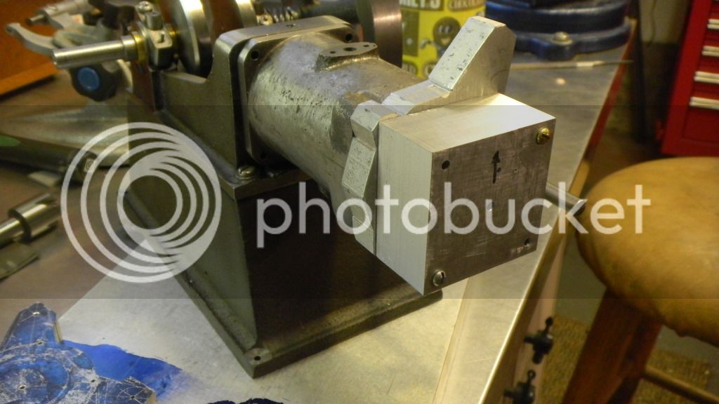
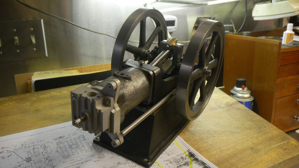
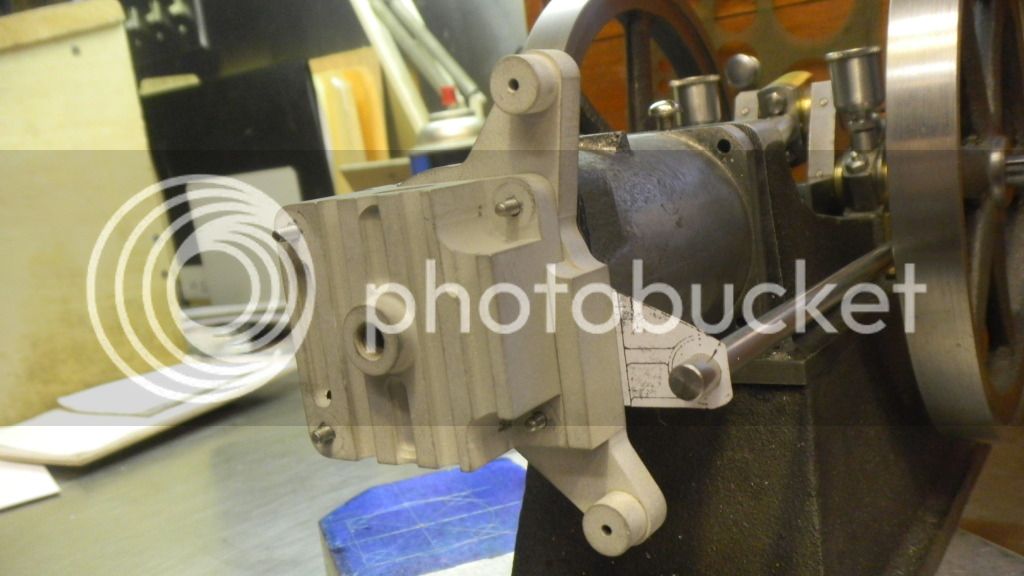
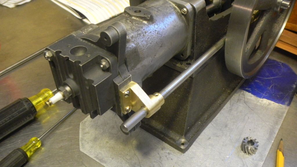
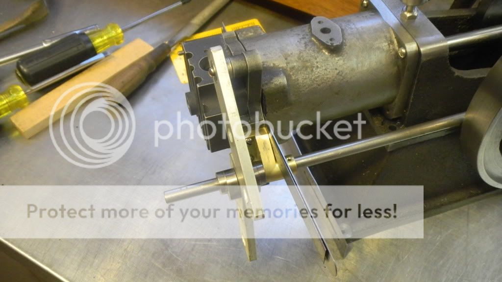
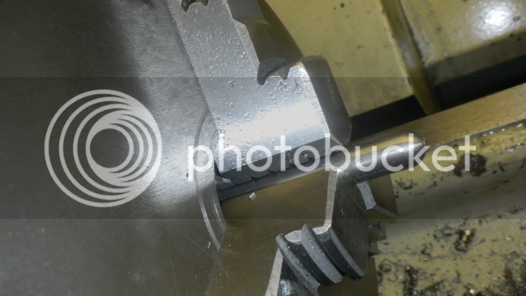
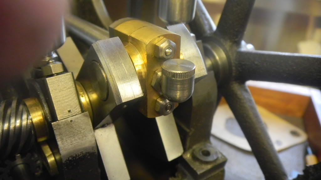
One more teensee little problem. Ive run out of space on the crankshaft. The hub of the flywheel is larger than the drive gear and will have to be spaced farther out.
Also the drive gear will have to be spaced away from the engine base in order to keep it centered over the driven gear. The outside of the hub is now flush with the shaft., and the gib key will protrude beyond.
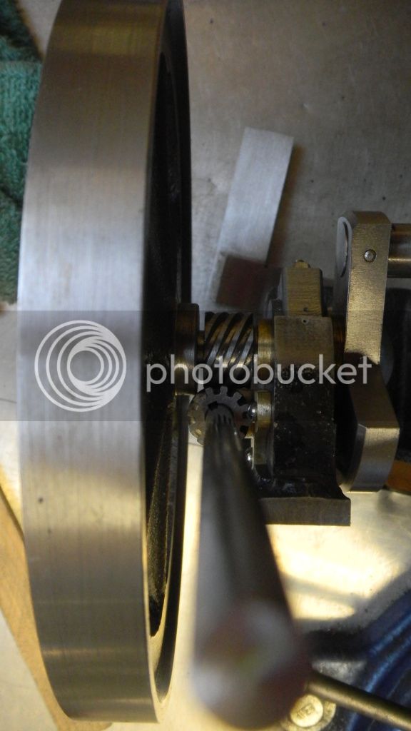
I thought I allowed enough extra length on the shaft, but its now perfectly apparent that I didnt plan far enough ahead. I cant leave it like that so now I have to make some adjustments.
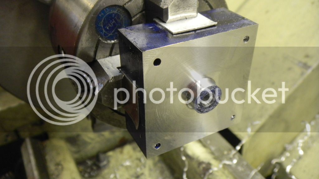
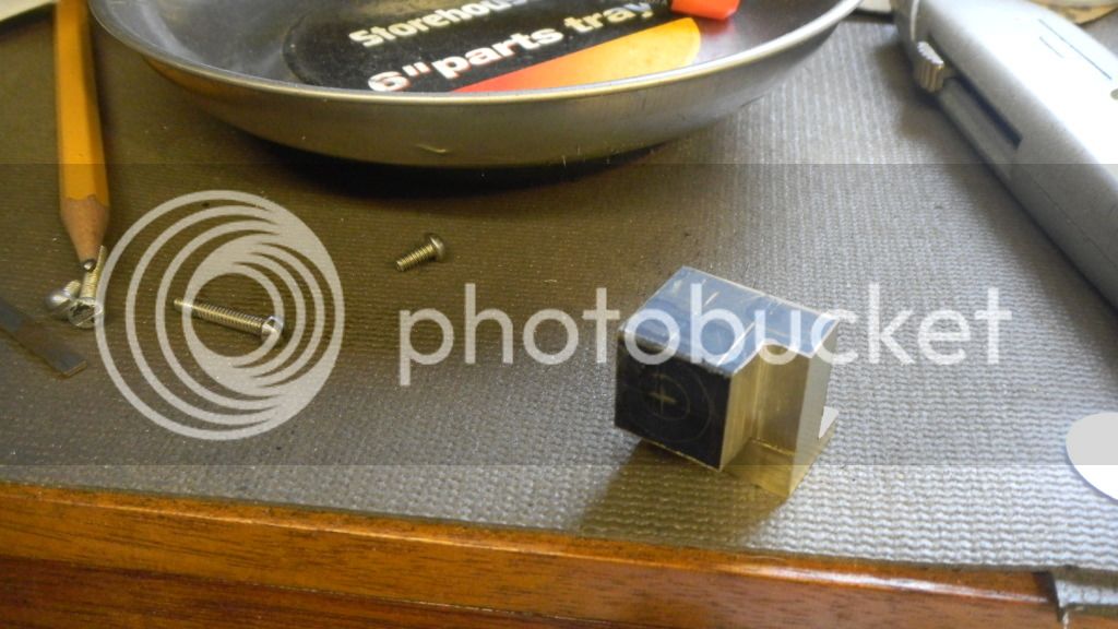
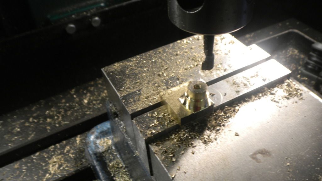
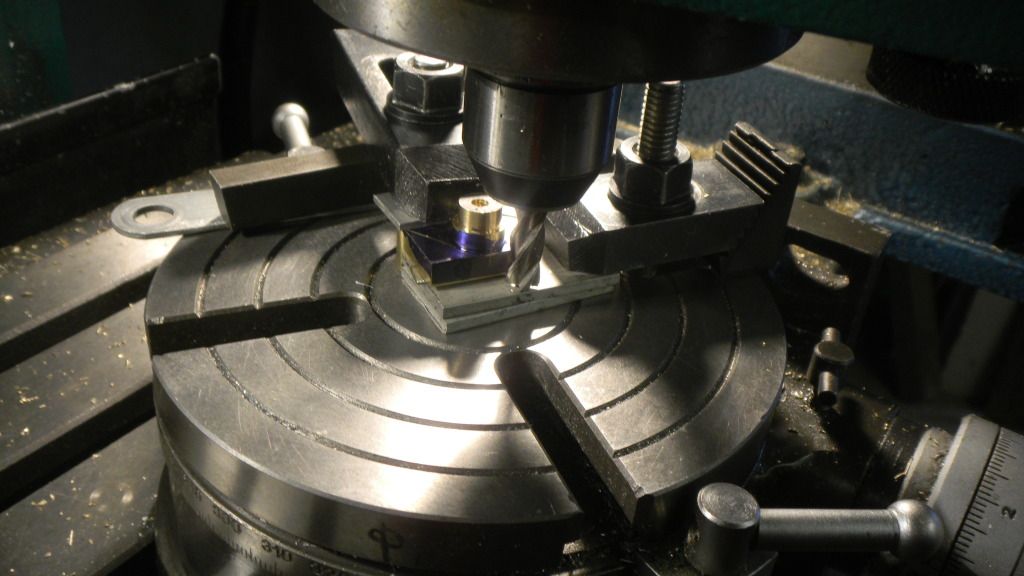
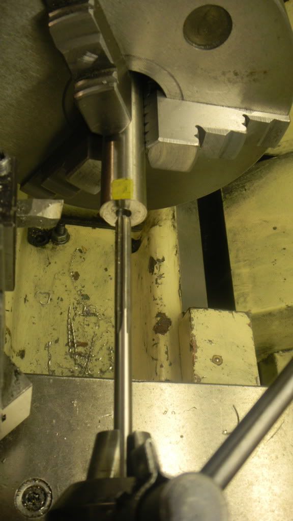
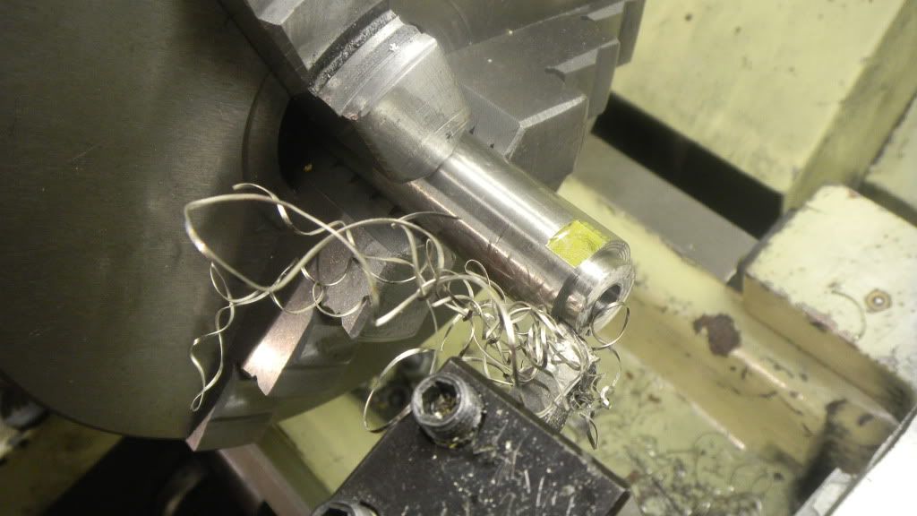
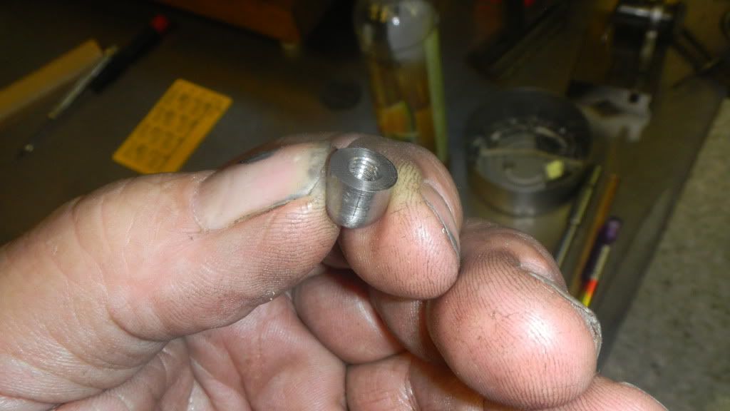
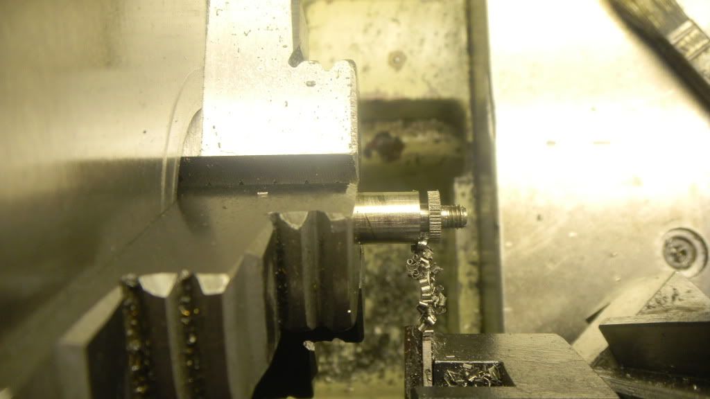
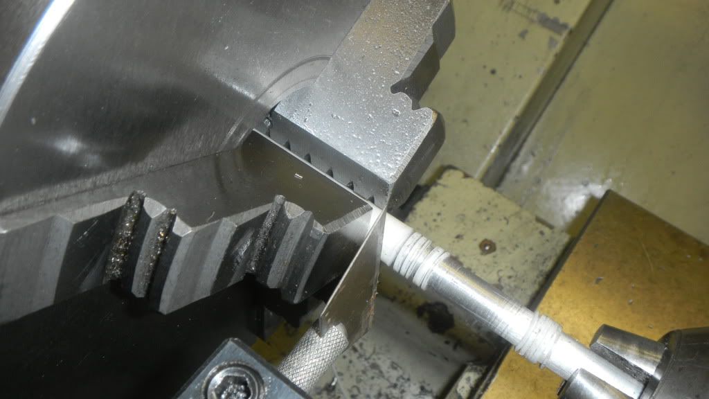
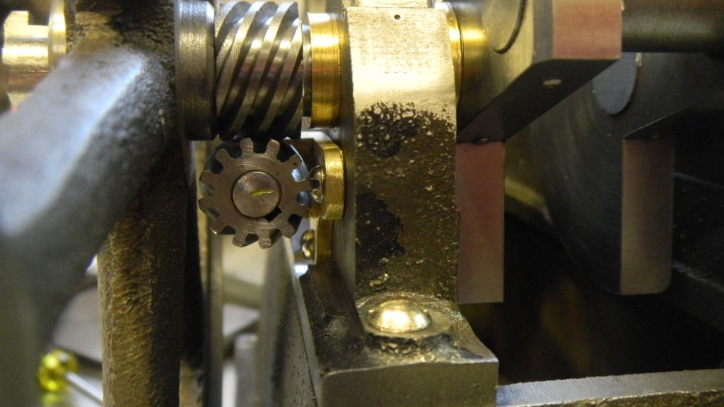
First and most apparent is to reduce the inner hub diameter, also while in the lathe I can trim the projection a 32nd.
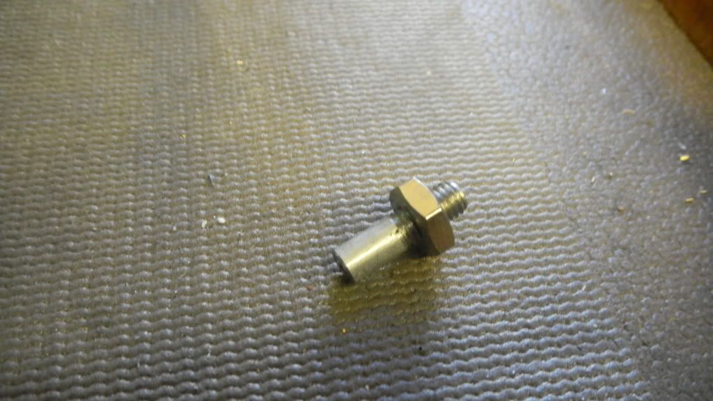
Still not enough gain in space. I will reduce the thickness of the sideshaft bracket mounting and mill a bit more of the engine base. About another 32nd each. This ought to do it.
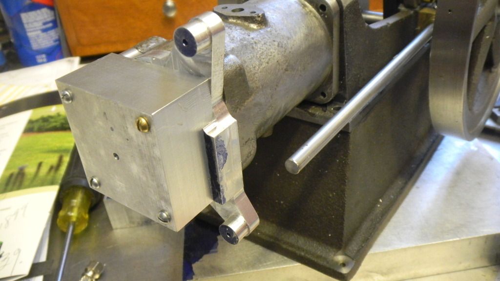
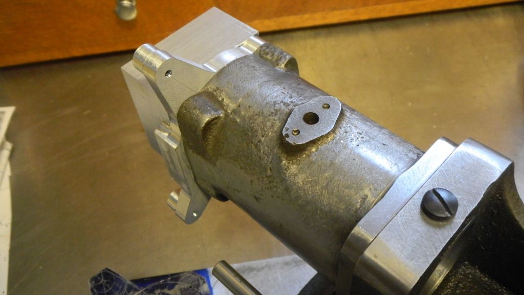
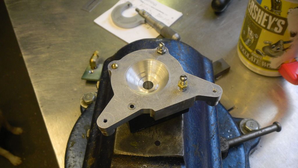
Modifications now made the results are great. All seems to be OK on that end of the engine.
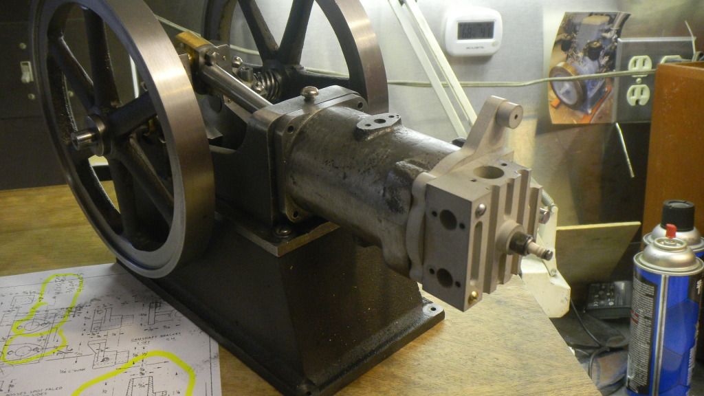
Now moving to the front line.
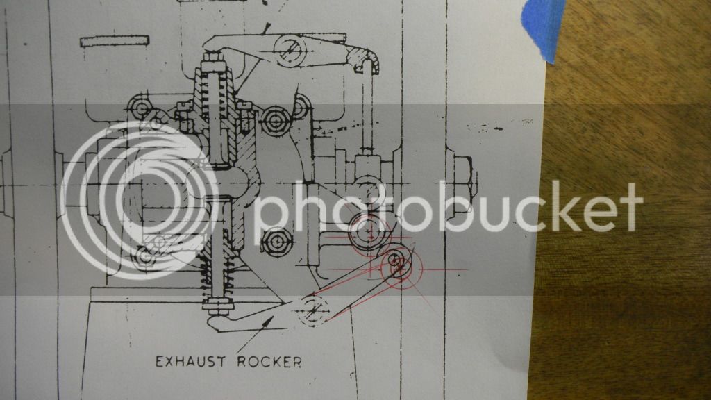
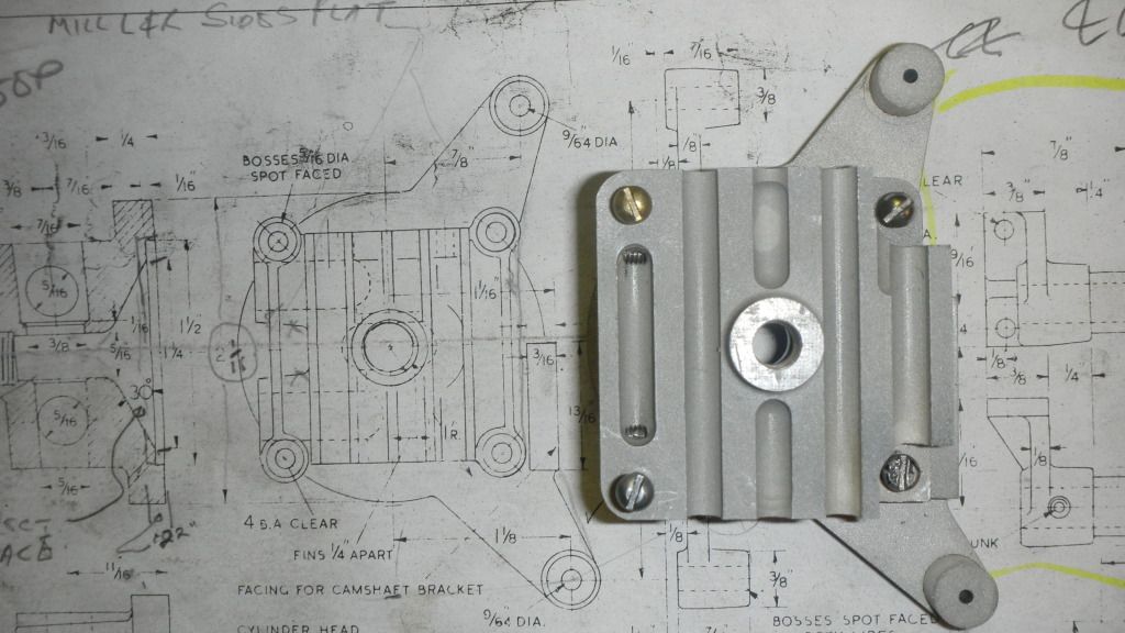
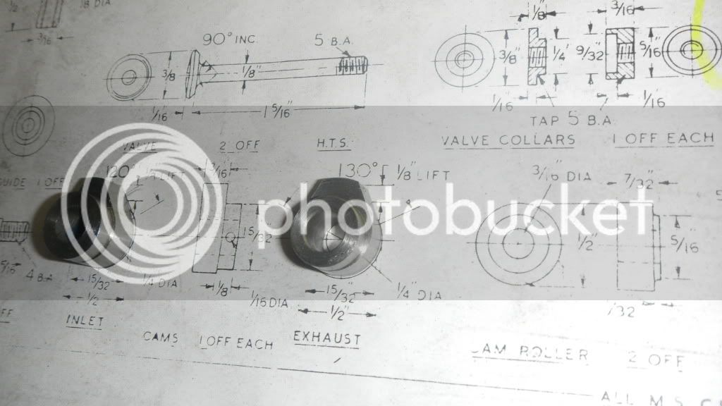
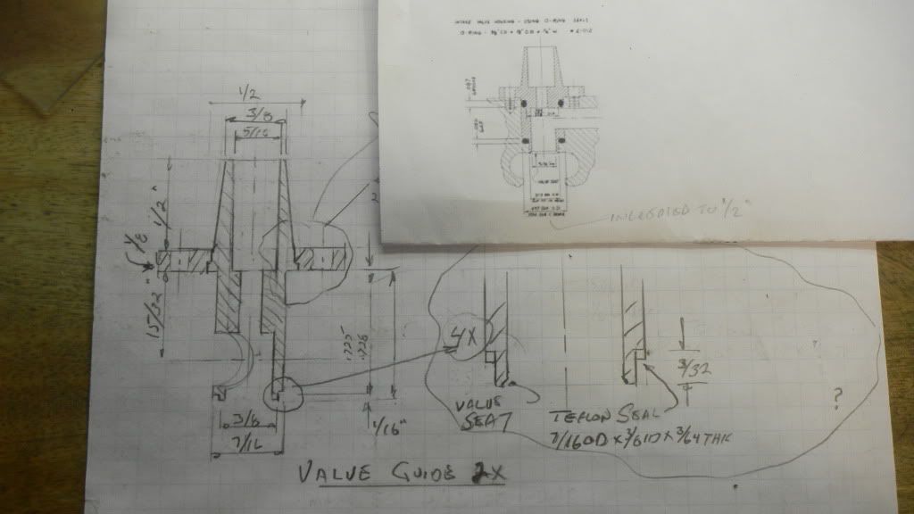
Ive been scrutinizing the cylinder head details for about 3 or 4 months.
It will be a serious challenge for me.
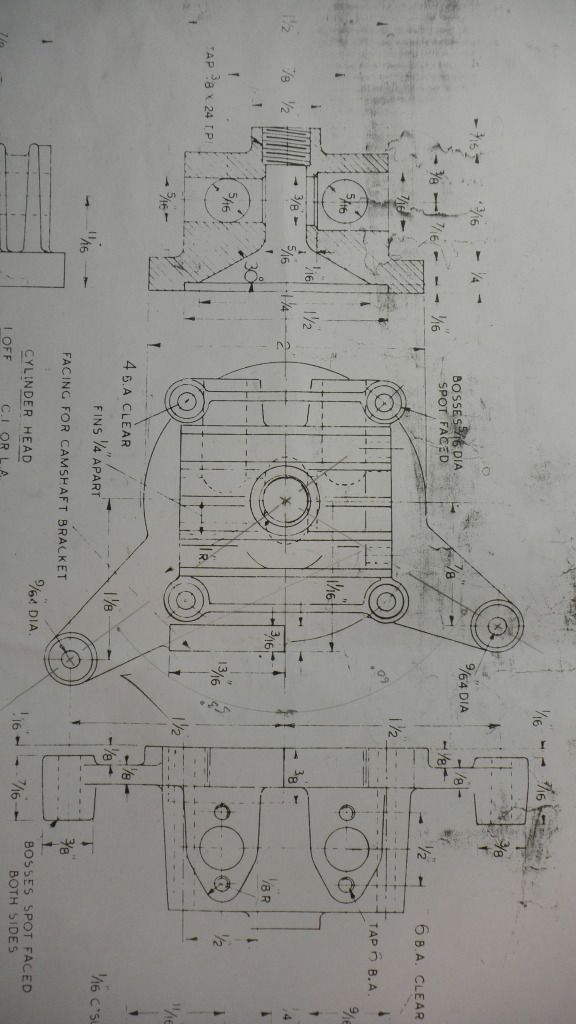
 
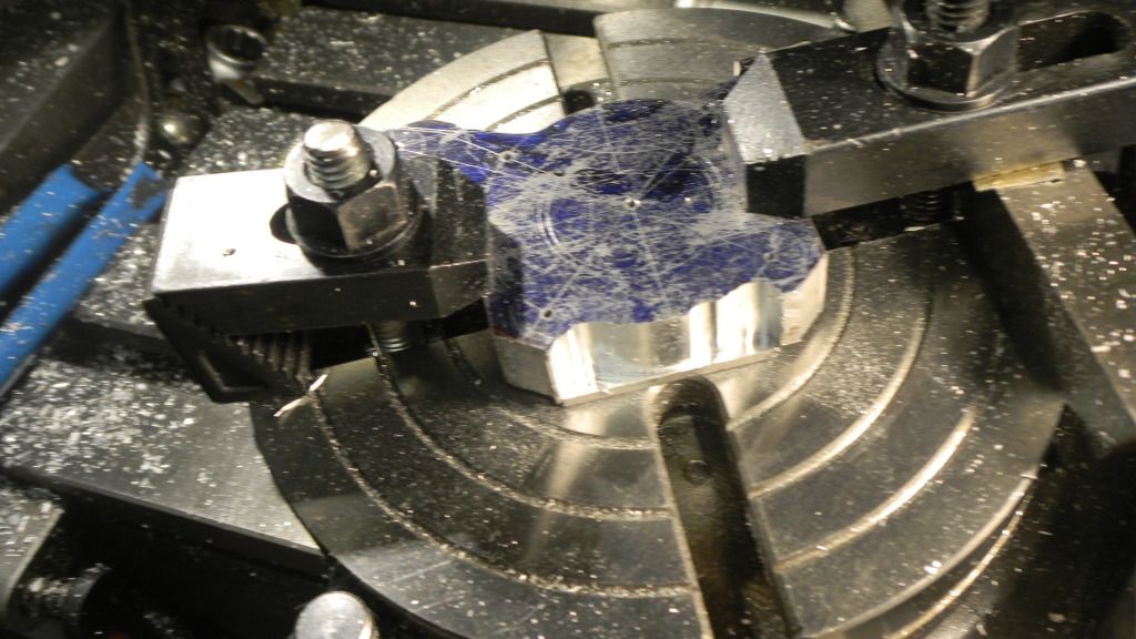
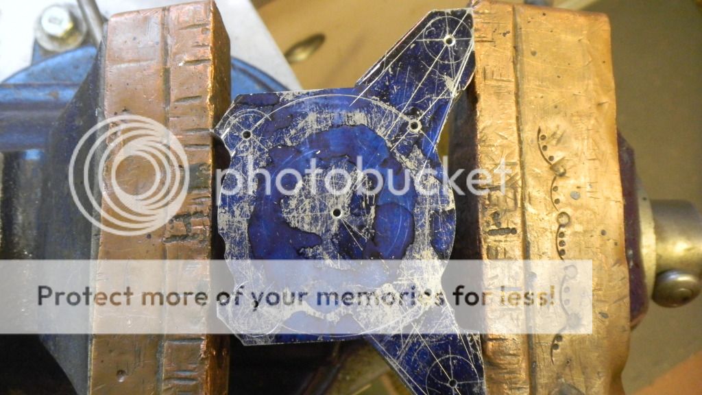
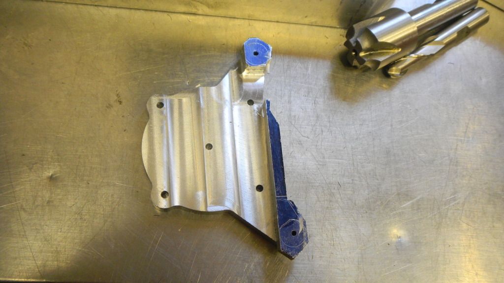
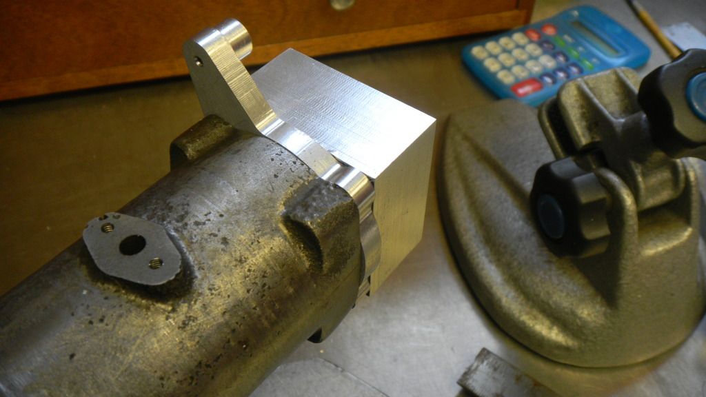
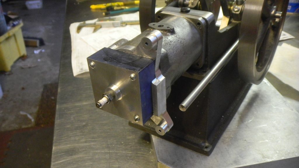
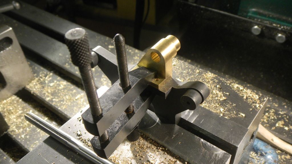
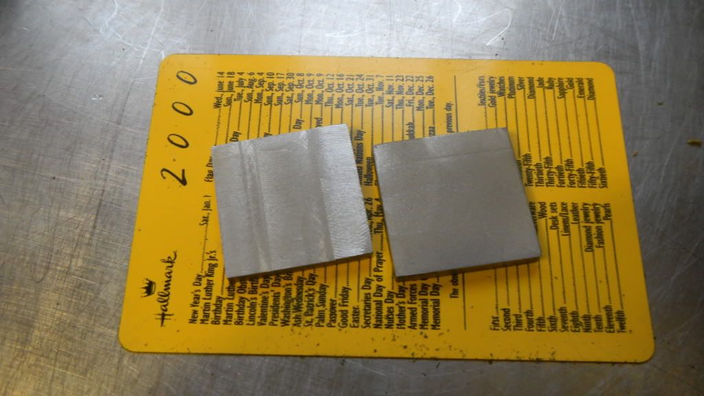
If I think like Im going to build a casting pattern for this piece, I can see it being built of a few individual pieces.
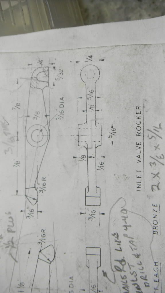
The base, IE: cylinder cap/rocker arm brackets and side shaft bracket mounting.
This part will have to accommodate these parameters and provide a landing pad for the actual cylinder head, as well as providing part of the combustion chamber.
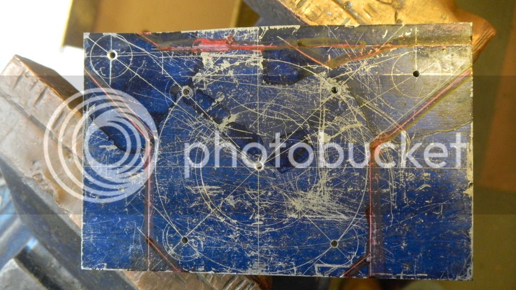
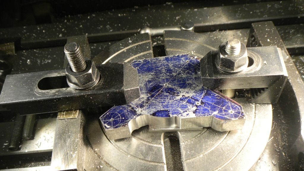
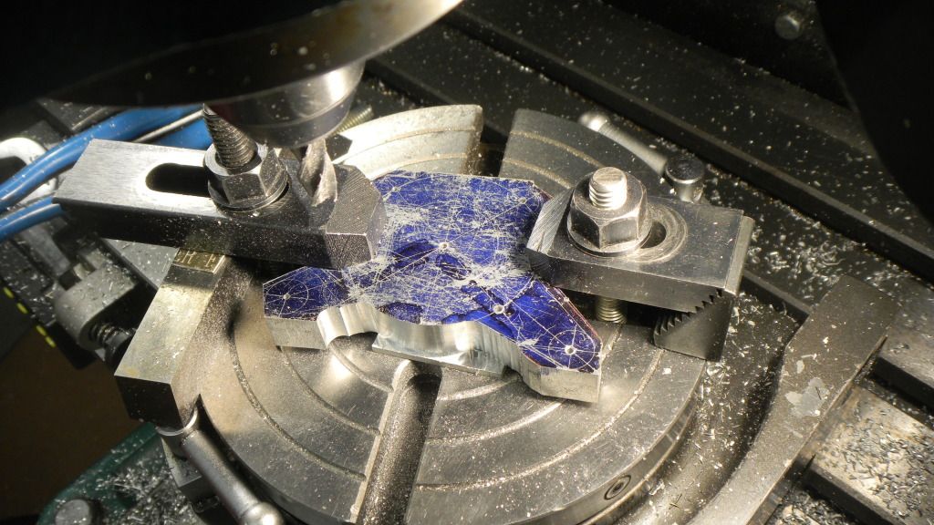
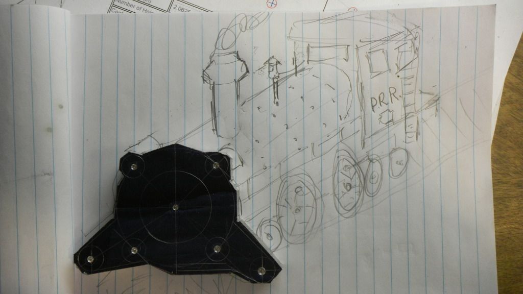
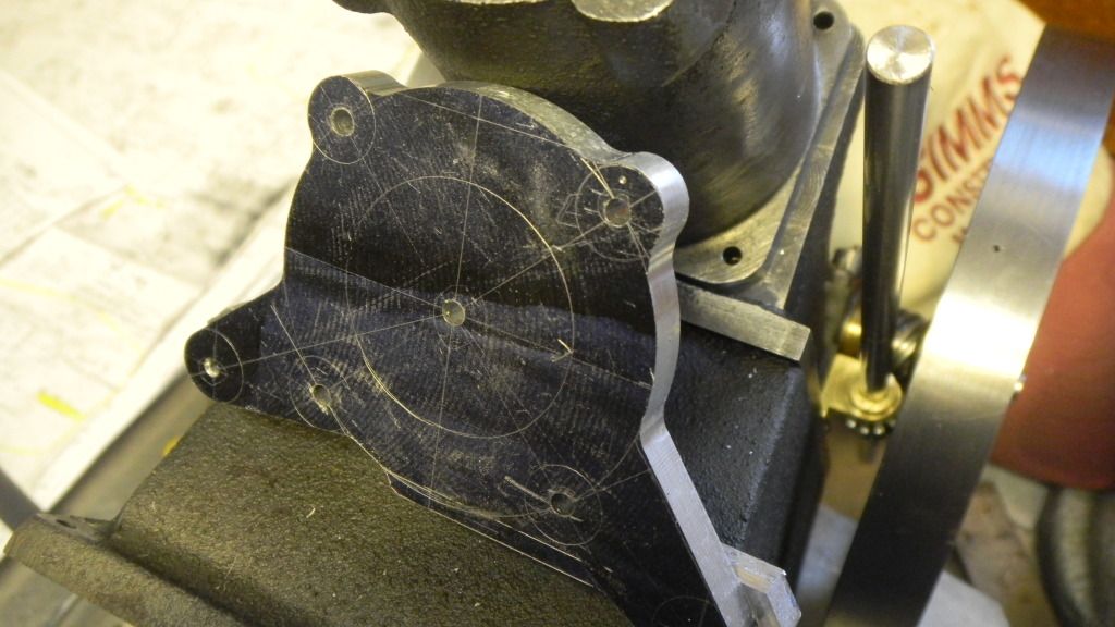
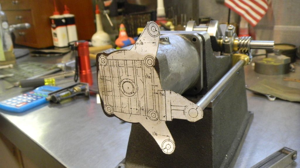
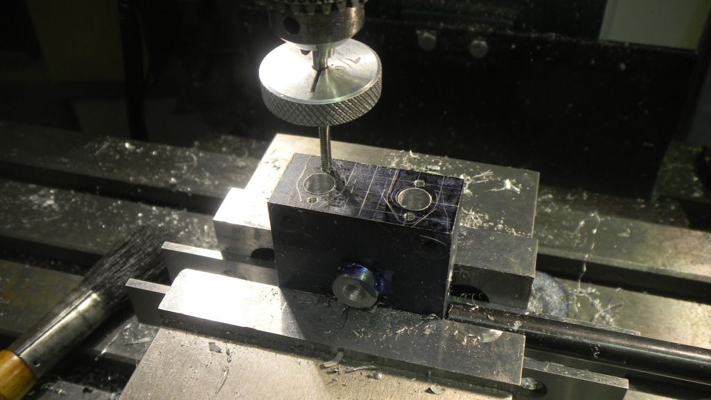
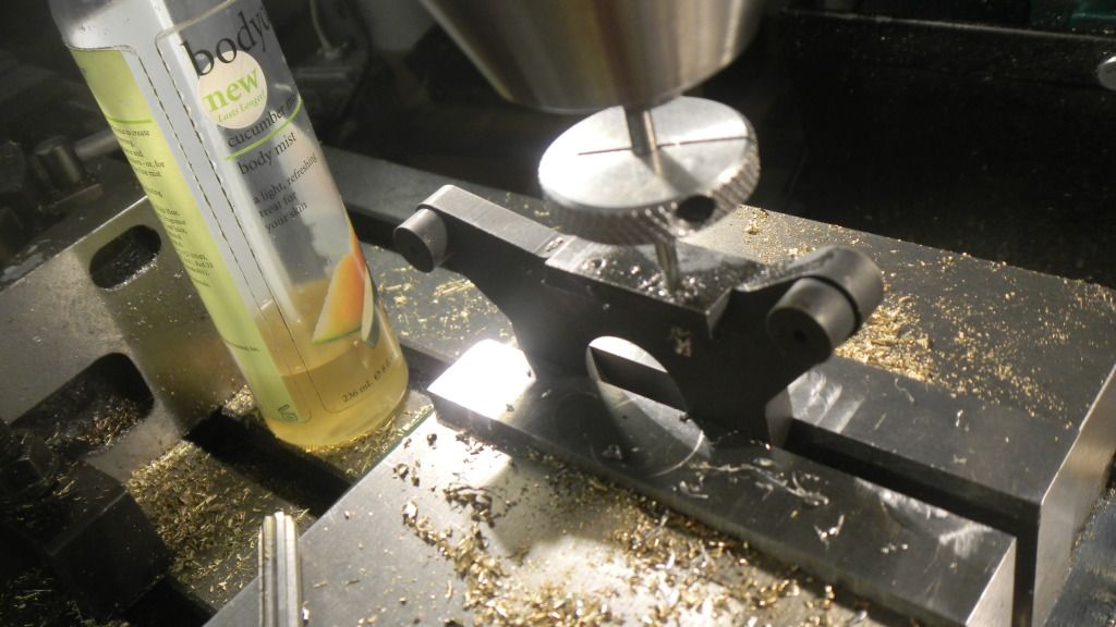
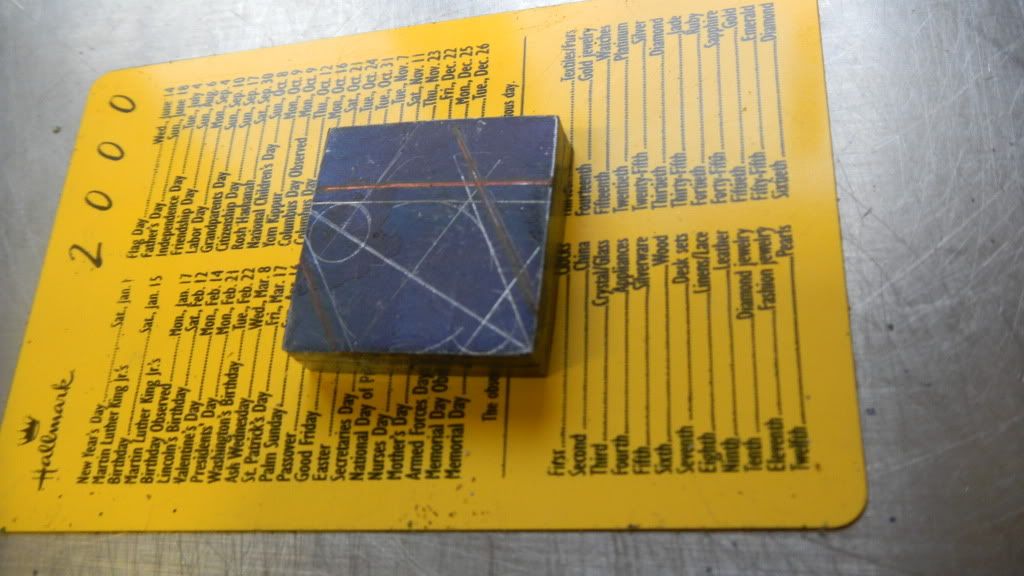
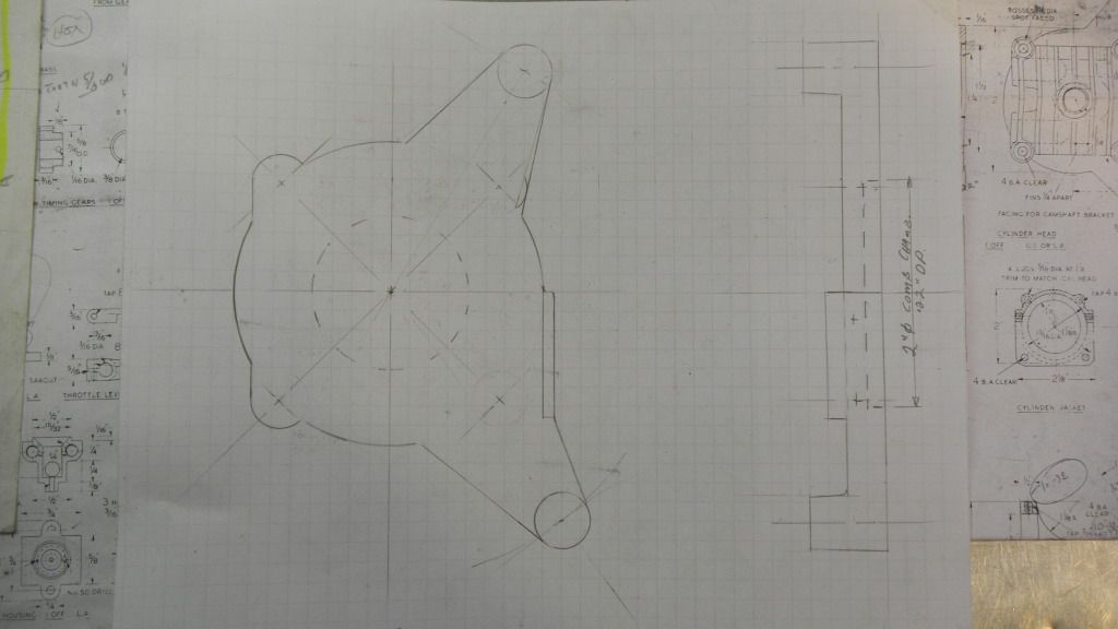
A few sketches, much what-iffing and Ive come up with this, as the first and easiest piece.
Also the drive gear will have to be spaced away from the engine base in order to keep it centered over the driven gear. The outside of the hub is now flush with the shaft., and the gib key will protrude beyond.
I thought I allowed enough extra length on the shaft, but its now perfectly apparent that I didnt plan far enough ahead. I cant leave it like that so now I have to make some adjustments.
First and most apparent is to reduce the inner hub diameter, also while in the lathe I can trim the projection a 32nd.
Still not enough gain in space. I will reduce the thickness of the sideshaft bracket mounting and mill a bit more of the engine base. About another 32nd each. This ought to do it.
Modifications now made the results are great. All seems to be OK on that end of the engine.
Now moving to the front line.
Ive been scrutinizing the cylinder head details for about 3 or 4 months.
It will be a serious challenge for me.
 
If I think like Im going to build a casting pattern for this piece, I can see it being built of a few individual pieces.
The base, IE: cylinder cap/rocker arm brackets and side shaft bracket mounting.
This part will have to accommodate these parameters and provide a landing pad for the actual cylinder head, as well as providing part of the combustion chamber.
A few sketches, much what-iffing and Ive come up with this, as the first and easiest piece.