
You are using an out of date browser. It may not display this or other websites correctly.
You should upgrade or use an alternative browser.
You should upgrade or use an alternative browser.
Tiny I.C. Engine
- Thread starter putputman
- Start date


Help Support Home Model Engine Machinist Forum:
This site may earn a commission from merchant affiliate
links, including eBay, Amazon, and others.
Yeah I know Arv, of course you are correct but I have two other irons in the fire at this time and am afraid if I begin something else I won't finish what I already have started and the cyle would continue. That is a pretty slick engine.
BC1
Jim
BC1
Jim
- Joined
- Feb 17, 2008
- Messages
- 2,326
- Reaction score
- 440
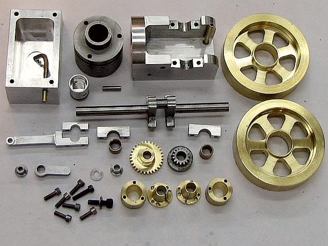
An Air Cooled Tiny is under way.
This engine is all Arv's geometry with only changes to suit my personal preferences and tools so no drawings or other details will be supplied.
To make it air cooled, the water hopper was removed leaving a 1/4 wall for the cylinder to mount to. The cylinder was made of cast iron with fins for cooling and the head mounting holes were extended through the fins to the tapped face of the frame.
For personal preference, the flywheels are fitted with taper lock hubs instead of set screws for mounting. If you look at the split taper inserts you will see 5 holes. Three of them are to pull the taper lock into the female portion of the hub and two of them are tapped to release the male part from the female part to disassemble or adjust. All holes are for 0-80 threads.
The crankshaft was extended 1/16 inch one one end to better fit my flywheel as my hub is a little thicker than Arv's. This is for the side of the engine that has the gears. The other end was extended 3/8 inch to allow room for a pulley to mount to drive some sort of external load if desired. The crankshaft also has counterweights incorporated. This is really cosmetic on an engine of this size and intended RPM, but as I turned the crankshaft from 3/4 inch diameter bar stock the metal was already there so very little extra work was required.
The fuel pick up tube in the fuel tank is offset from the center line as I think it will be easier to install the fuel tube. It also let me use a close fit hole in the fuel tank for the tube as I could insert it from the inside and rotate it into position.
On the frame, I put an extended fuel filler tube instead of the threaded plug. I may put a cap on the exposed end but I have not decided on that. I will wait to see how it looks after assembly.
This how things are at the end of day 16 since first metal was cut, but there were 5 days I was not in the shop. Most everything up the cylinder head are machined, but will need some finish work done for cosmetic purposes during assembly.
Gail in NM
Gail - wow, where did this come from?! Very nice, have you started your own build thread or are you just going to post on the bottom of this. Arv, once again nice design and nice to see somebody has already got well on with a build of your engine.
Well done to both of you. :bow: I will start looking at this after my poppins are done so may be a while off yet!
Nick
Well done to both of you. :bow: I will start looking at this after my poppins are done so may be a while off yet!
Nick
- Joined
- Feb 17, 2008
- Messages
- 2,326
- Reaction score
- 440
Thanks Nick,
I am just going to post here in Arv's (PutPutMan) excellent thread. It is the same engine functionally and the drawings are here in this thread. Besides it shows how to make something that looks a lot different without changing any functional dimensions. maybe encourage others to play a bit with design.
Arv: Only one bust found in the drawings so far. The spacing between the crankshaft webs is shown as 0.156, the same as the width of the connecting rod. I thinned the crank webs down to put 0.187 between them. A quick scaling of one of your photos leads me to believe that you thinned the connecting rod down to 0.141 to provide the clearance. Either way will work, so no big deal except that some way must be used to provide some clearance. If the parts are built to the drawing, the connecting rod could be slimmed down afterwards so it should not mean anyone having to remake any parts.
Gail in NM
JRNYMAN2LMAYKER
Active Member
- Joined
- Mar 29, 2009
- Messages
- 29
- Reaction score
- 4
Dang Gail, you beat me to the punch!!!! I have redrawn the cylinder for an air cooled version as well, however, the design is slightly different than what you have. It appears more like the version Hamilton Upshur used on his 3/4" bore model. I am curios to see what you actually come up with as far as springs are concerned. Per Arvs' reccomendation I have been scrounging the local hardware stores for different spring sizes and lengths.
i have all of the materials gathered and rough cut into a sort of kit form but just waiting to have all the stuff before making chips.
Good work my friend........
Greg
i have all of the materials gathered and rough cut into a sort of kit form but just waiting to have all the stuff before making chips.
Good work my friend........
Greg
putputman
Senior Member
- Joined
- Nov 22, 2008
- Messages
- 600
- Reaction score
- 55
Gail, coming along good. I like your flywheels. The spoke pattern really looks nice. I think your tapered locks will work better than the set screws. I know when I used that design on larger engines, the flywheels run true.
I am curious as to why you made a three piece flywheel instead of a two piece one.
I will check the drawings on the crankshaft & con-rod again. I know I changed some dimensions on the crankshaft after I built the second one. I guess if that is the only mistake left on the drawings, I am happy.
Looking forward to see that one running.
- Joined
- Feb 17, 2008
- Messages
- 2,326
- Reaction score
- 440
Thanks Rudy, but Arv is the inspiration and I am just playing copy-cat. This is just what you need if you ever want to go down from your Upshire in size.
Greg, I will be looking forward to your build. For springs I will probably just wind my own. Years ago I bought a box of one pound coils of music wire at a local going out of business of a machine shop. Wire sizes from way too small to way too big. If we get the springs nailed down I can mail you some wire to wind your own.
Arv, The three piece flywheel is because I hate to set up the lathe to cut the taper in the flywheel bore. I have an old CNC lathe so I made a production run of the male and female taper locks many years ago so I just have to put a straight bore in the flywheel and Loctite them together. I have not finished turned the rim of the flywheel so I will do that on an arbor after the hubs are mounted. Actually this bit me this time as I only had one hub set left in the drawer so I made a run of 25 more so I won't have to do it again for a long time. Probably they will last until I can't build models any more. I have both a CNC lathe and mill, but most of this engine will be built manually. The flywheel hubs and flywheel spokes are about all so far. I will probably turn the spark plug bodies on the CNC lathe also as it is easy to thread close to a shoulder with it.
On the spark plugs, I am planning to change the thread from 10-32 to 10-40. I have taps and dies for both, but 10-40 is a sort of standard for model spark plugs and commercial ones are available. It won't do any good in this case because of the extended nose needed for this engine won't let us use a commercial plug any way, but it keeps things the same around here.
Gail in NM
putputman
Senior Member
- Joined
- Nov 22, 2008
- Messages
- 600
- Reaction score
- 55
Gail, I checked my engine against the prints and found that I had cut the connecting rod down to .140 width. That gives it the necessary clearance.
I removed the print #8 rev B and replaced it with rev C. I think anyone that has got that far with the build can merely do as you suggested and norrow up the con-rod.
One thing I found with my engine is that the standard o-ring does not last very long. It may be that I don't have a highly polished cylinder bore but I think maybe it is more of a heat problem than a wear problem. The guy I buy my o-rings from ordered some Viton rings for me. They will stand 400 degrees vs the 200+ of standard rings. So far they seem to make the difference. I ended up with 30 of them. I will throw a few in an envelope & send them to you. I still have your address.
Greg, if you will PM me your mailing address, I will send some springs to you. I have quite a few of the very light ones. As I told you before they are light tension springs and I stretch them out to make compression springs out of them. Then cut them to length so that the free length and the compressed length is almost the same for the intake valve. You just need enough pressure to close the valve. The cylinder compression will seal it from leaking.
- Joined
- Feb 17, 2008
- Messages
- 2,326
- Reaction score
- 440
Thanks for the Viton O-rings, Arv. I have other sizes of Viton on hand, but was going to order some for this engine soon. I have a Buna-N (nitrile) installed in it right now, but I think you are right about the heat getting to Buna-N as Buna-N has better abrasion resistance.
For reference, Enco, MSC, and McMaster all have them in packages of 100 for about $10. My local seal shop also stocks a full line of them, but it would cost me $10 to drive over there to get them. On line ordering is normally the cheapest for me on most items as I live far from the industrial centers in Albuquerque.
Thanks for updating the prints. It will make it easier for the next guy to do a build.
Not much will get done on the Tiny for a few days. Have to go play games with the MD's on Monday morning and it will be late in the week before I can get back in the shop safely, although I will probably be on the computer again on Tuesday.
Gail in NM
- Joined
- Feb 17, 2008
- Messages
- 2,326
- Reaction score
- 440
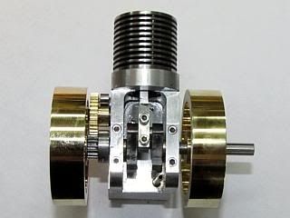
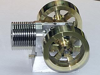
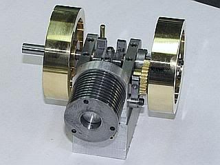
This morning's appointment delayed until after lunch so I have time to post a couple of photos of the previous parts put together. I decided that this engine will look better with a matt finish except for the brass flywheels which have polished rims. The head may get polished also after I look at it when it is built.
Gail in NM
Gail in NM
- Joined
- Feb 17, 2008
- Messages
- 2,326
- Reaction score
- 440
Thanks Arv and Nick.
Arv: Thanks for the care package of 0-rings. I am going to use the same ignition system that you used. I bought one a little while back to retrofit an engine I built about 8 or 10 years ago, but I have not gotten around to doing the retrofit yet. The cylinder will lbe held in place by three 2-56 x 1.5 SHCS, but I have to cut about 1/8 inch off. As usual I have two short and too long screws on hand.
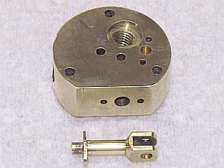
I finally got back into the shop yesterday and got the head and standoff done. A few changes on each of course. Still the same operating geometry, but a few personal preferences thrown in.
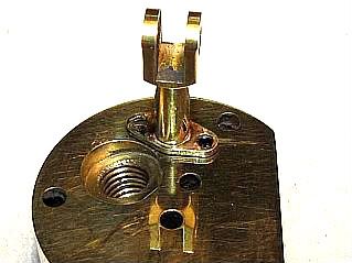
On the head, I changed to 10-40 for the spark plug thread. I rotated the exhaust hole to come out horizontal and threaded it so I can screw in different exhaust systems. It is spotfaced for a locknut. The intake remained the same, but I did add two 0-80 threaded holes to hold a flanged mixer body in place with two 0-80 SHCS. The standoff hole is just a plain 3/32 drilled locating hole and the standoff is held in place by two 0-80 SHCS. All cosmetic and personal preference. It's still Arv's engine geometry with just a different look.
The standoff is flanged and held in place with two screws.
Gail in NM
Arv: Thanks for the care package of 0-rings. I am going to use the same ignition system that you used. I bought one a little while back to retrofit an engine I built about 8 or 10 years ago, but I have not gotten around to doing the retrofit yet. The cylinder will lbe held in place by three 2-56 x 1.5 SHCS, but I have to cut about 1/8 inch off. As usual I have two short and too long screws on hand.
I finally got back into the shop yesterday and got the head and standoff done. A few changes on each of course. Still the same operating geometry, but a few personal preferences thrown in.
On the head, I changed to 10-40 for the spark plug thread. I rotated the exhaust hole to come out horizontal and threaded it so I can screw in different exhaust systems. It is spotfaced for a locknut. The intake remained the same, but I did add two 0-80 threaded holes to hold a flanged mixer body in place with two 0-80 SHCS. The standoff hole is just a plain 3/32 drilled locating hole and the standoff is held in place by two 0-80 SHCS. All cosmetic and personal preference. It's still Arv's engine geometry with just a different look.
The standoff is flanged and held in place with two screws.
Gail in NM
- Joined
- Nov 12, 2009
- Messages
- 1,427
- Reaction score
- 221
Hi putput
have just downloaded your plans to see if my poor eyesight will alow me to build one
hope so as it about time i started something new.
anyway 1K to U with thanks from the land of Oz
Cheers Pete
have just downloaded your plans to see if my poor eyesight will alow me to build one
hope so as it about time i started something new.
anyway 1K to U with thanks from the land of Oz
Cheers Pete
putputman
Senior Member
- Joined
- Nov 22, 2008
- Messages
- 600
- Reaction score
- 55
Gail, glad you received the package O.K. I have plenty more if you find you need more. So far I have started my engine several times every day & the o-rings are holding up good. The old buna-n rings would only work for a few days.
I like your stand off. It will give your engine some nice class. Can't wait to see your exhaust system.
I have 0-80 screws and a tap, but have never tried using it. I think 2-56 might be my limit.
Pete, I think you should go for it. From the conversations I have had with Gail, he has some serious handicap with his eyes also. It certainly doesn't show in his work though. Perhaps he can give you some tips on how to work with that handicap.
Look forward to following your build and will help in any way I can.
- Joined
- Feb 17, 2008
- Messages
- 2,326
- Reaction score
- 440
Pete,
Jump on in. Don't let not being able to see all the part details stop you. It may slow you down a bit, a lot sometimes, but if you have some engine building experience the "Tiny" is not too bad. I used some 0-80's because I have worked with them a lot over my life, but 2-56 is the smallest that Arv used on the basic design. And Arv, or I, will help you if you need and detail clarification on the plans. Besides, Arv would probably like for SOMEONE to actually follow his plans. I never was very good a following instructions.
Arv,
Thanks for the approval on the stand off. The flange was made separate and silver soldered to the post. For anyone who might be interested, the flange is rotated 15 degrees so I made the included angle on ends of the flange 30 degrees so it just is aligned to the flat side of the fork to braze up. I also drilled the holes in the flange a little bit oversize so I can rotate it a bit to align the rocker arm if necessary.
0-80's are not that bad. It's mostly feel. All tapping is done with a spring loaded driver in the mill to make sure the tap is perfectly in line with the hole. I use form taps, so no chips are made to bind up the tap. They are great for blind holes and I seldom use cutting taps except for larger sizes or special sizes. Hole size is more critical, and different, than for cutting taps is the only precaution.
I really like your idea of using the center electrode to support the PTFE insulator while machining. Never thought about doing that. I have a small rotating ball bearing tailstock chuck that I use to support long skinny parts while machining and it will work perfect for that. I am a little worried about drilling the very deep 1/32 hole in the spark plug insulator. My 1/32 drill bits only have .625 of flute so I guess that a lot so very fine peck drilling will be necessary to clear the chips. The drill bits are long enough so that is not a problem. I will find out soon enough.
The basic body for the spark plug is made, but other than the 0.079 hole being drilled through it I have not done any internal work. I am also making some copper washers to seal the spark plug. I just feel more comfortable with them in place to prevent leakage. OD of 0.265, ID of 0.190 and 0.029 thick. I cut some extra bodys and washers in case I ruin up a body. If I am lucky and don't mess up there are enough that some one can have one if they need it for a Tiny build and I will still have a spare.
No more work until tomorrow. Family get together in a couple of hours that will wipe out the rest of the day. It will be fun however with 3 of the 4 grandkids there.
Gail in NM
Gail in NM
Similar threads
- Replies
- 28
- Views
- 4K
- Replies
- 6
- Views
- 786
- Replies
- 25
- Views
- 3K
- Replies
- 413
- Views
- 38K