Tiny I.C. Engine

Home Model Engine Machinist Forum

Help Support Home Model Engine Machinist Forum:

This site may earn a commission from merchant affiliate links, including eBay, Amazon, and others.
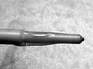
The rest of the assembly is just gluing the parts together with epoxy. Use a fairly thin epoxy so the excess can squish out between the insulator and body when assembling. I use ordinary 5 minute epoxy.

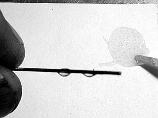
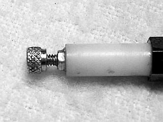
First the wire is glued into the insulator. Coat the wire with some epoxy and press into the insulator. Clean off any excess epoxy.

Spark-0005.jpg
Spark-0006.jpg


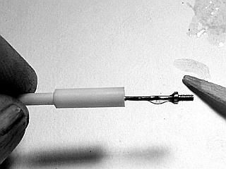
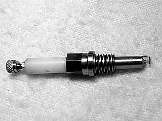
After the epoxy has cured on the wire, coat about half of the insulator at the small end with a fres h batch of epoxy. Insert the insulator into the body until the tip of the center electrode almost touches the ground electrode.
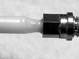
Clean off any excess epoxy. Use a feeler gauge or a small piece of 0.025 sheet metal between the electrode tip and the ground electrode to set the gap at about 0.025 inch. If you are gentle you can remove the feeler gauge. Allow the epoxy to cure.

Spark-0007.jpg
Spark-0008.jpg


Spark-0009.jpg
Spark-0010.jpg


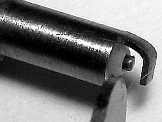
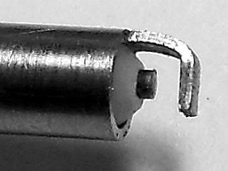
Tweak the ground electrode to set the gap if it has changed and you have a finished spark plug.

Spark-0011.jpg
Spark-0012.jpg

 
Good post Gail. I totally understand after seeing the pictures and your print. When the time comes for my turn at one of these small ones, I'm sure I can do it.

Is your plug lined with Delrin, or one of the other materials you listed on the print? I'm looking at the earlier print in the archive. I just spotted the latest one in your post, and it specifies Corian.

-MB
 
MB,
Yes, the current plug insulator is Corian (acrylic). My first plug used Teflon (PTFE). PTFE has a better voltage breakdown and higher temperature rating than either Corian or Delrin (acetal), but is so soft that it makes it hard to machine. A lot of people have used (including me) have used Corian with out a problem. Delrin should work very well if you happen to have some. Probably ought to cut some shallow grooves in the side or otherwise prepare a rough finish for the epoxy to grip on as almost nothing will stick to it. Same problem with PTFE. All are satisfactory so take your pick.
Gail in NM
 
Thanks Gail.

I'm soaking up all the info I can find, like a fresh sponge.

-MB
 
Got my new Hall effect sensor in the mail today , got it installed, played around with the timing a bit, and carb. So I shot a video. New to all this photobucket--youtube stuff so I hope it works.
John

[ame]www.youtube.com/watch?v=BJM7C6sCb2g[/ame]
 
She runs good John. Thm:
Nice job, all around. The throttle seems to work out for ya pretty good.

The fuel tubing between the carb and head should help out with the vapor lock problem some of us have had.

Kel
 
Hi John. The video is super! Your engine sounds really good. Congratulations! :bow:

I would love to see (close up pics?) and hear the details about the throttled carb, is it an off the shelf item?

How is you Hall sensor mounted?

And also the connector plugs you used on the base to hook up your CDI.

An inquiring mind would like to know. ???

-MB

 
Thanks guys,
Kel-The fuel tubing does keep it from vapor locking, but I'm gonna change something, it's just suspended there on tubing, also if I stop , it manages to siphon fuel out of the tank, onto the base. I would like turn the carb out some, attempted it once-- made another part that went into the "oops" box.

MB--The carb is from the prints with the addition of a valve that Kel showed in his post on page 9 of this post. (Thanks Kel) I mounted the hall sensor on a thin piece of Plexiglas that is mounted just above the fuel tank, the wires enter the frame and snake over to a point where I drilled a hole down through the wall of the fuel tank to get to the base.
The connectors came from A MAIN HOBBIES.com I used E-FLITE EC3 device and battery connector (pn EFLAEC303). The Hall sensor is connected using Futaba style connectors (pn PTK-5008) which were compatible with the connector on the sensor from S and S machine.

Hope that helps
John
 
Well I played around with 'Tiny' for several hours today, double checked the seal on the valves, installed a new 'O' ring on the piston and sealed the head gasket surface. It fired right up but I'm still not convinced about the 'O' ring. I can't start it by hand like
John does with his. I'm happy with the outcome although I think I will make another piston with a cast iron piston ring and try that. Here's the latest video clip. I used a model airplane engine starter and put several layers of Duct tape around the aluminum starter hub.
George
[ame]http://www.youtube.com/watch?v=xJ7JRRNpJ6c[/ame]
 
George, she sure sounds like a good runner. My video was a best case scenario, I already had it running so it was warmed up. When cold she is a bit more stubborn. After you guys talked about timing, I bumped mine up abit, seems to run better, but occasionally at mid throttle it will start to surge. i'm not sure if this would be a carb thing or a timing thing. Any ideas?
 
I started with my timing about 5* BTDC with the timing lever available to add 15*. When I got it started and got the carb adjusted as well as could be I moved the timing lever to more advance. I could hear it smooth out just a small amount. When I would move it back it sounded like it was laboring a little. When I flip my engine over I can hear the intake valve vibrating as it's being pulled open but there's not much compression. As the engine heats up and parts expand there's enough compression to stop the piston from going over center when you flip it by hand. I would like to feel more compression when cold so I'll play with it. At that point maybe the timing will make more of a difference. I'll let you know what I find out.
George
 
John. Thanks for all the information. I already found the plugs, and their the way I want to set up my ignition. I also found the throttled carb details provided by Kel. The set up looks real good. I couldn't picture it in my mind and would have never thought of of doing it that way, outside of the convention buttery control.

I know very little about I.C. engines, but based on my experience with faulty I.C. powered yard equipment I would blame the surging on contaminated fuel. Is it possible theirs microscopic particles left over from the machining? Or fine particles in the fuel? I'm just guessing that might be the cause. I think I'llclean my fuel system parts with an ultrasonic cleaning unit, and run my fuel mix through fine filter paper just to eliminate that possibility.

Question; Is there any special wire you would recommend between the CDI and the engine mounted ground/spark plug wire? should they be separated?

-MB

 
MB I had Tiny hooked up and running on the bench with just cheap jumper leads and had no problems. But for the final hookups I used Test lead wire, for the plug wire and ground, mainly because of it's flexibility. I ran the ground and plug wire together in some tubing. The sensor wires I ran in a different tubing. I would try to keep the ground and plug wire separate from the sensor wires, although when I was bench running Tiny I had wires crossing and running over top of each other with no ill effects, except when it got flooded, then I had a problem with some arcing.

John
 
George, Have you tried a new O-ring? I had an issue with compression and upon replacing the O-ring (which was brand new already) I had better results with some verses others that cam put of the same bag.

I also added .020" to the top of the piston, to bump up the compression a little bit, however I did have to notch the piston a little to clear the spark plug.

Currently the compression is pretty darn tight, when I turn the engine over slowly I can feel it fire ever so slightly. If the intake spring holds tight that is. I got her pretty light.

Kel

 
awJCKDup said:
MB I had Tiny hooked up and running on the bench with just cheap jumper leads and had no problems. But for the final hookups I used Test lead wire, for the plug wire and ground, mainly because of it's flexibility. I ran the ground and plug wire together in some tubing. The sensor wires I ran in a different tubing. I would try to keep the ground and plug wire separate from the sensor wires, although when I was bench running Tiny I had wires crossing and running over top of each other with no ill effects, except when it got flooded, then I had a problem with some arcing.

John

John, Did the arcing occur between ground and plug wire, or the plug wire and sensor wire?

Did you need to replace the hall sensor after the arcing?

George, If you would like to try some O-Rings from a different batch let me know the size or industry number. I have a good supply of various sizes on hand. Good ones, not from a low cost discount assortment.

-MB
 
John., Nice running engine. Runs as well as it looks.

George, you mentioned trying cast iron rings. The smallest I have ever made were 1/2 inch diameter. That was a while ago and while my skills have improved some the 3/8 diameter still spooked me. That's why I took the cowards way out and did a lapped piston. I figure that rings should be about 0.013 inch square section. I will be watching to see how you make out if you try it.

I had problems with dirty fuel with the close fitting needle valve in the mixer. I started filtering mine through a coffee filter at that cured the drifting needle valve setting. I bought some standard lab filters, but have not used them yet.

I am using small test lead wire for my HT and ground connections.

Gail in NM
 
MB
The arcing was actually across the lugs on the coil on the cdi board, that's like an inch apart. I believe the sensor failure was from some dummy unintentionally touching the cdi board while it was running.......smarts a bit too. and yes that is when the sensor expired... lesson learned, I have spares now.


Gail-Do you run gasoline like George does, or do you use Coleman fuel?

To anyone who wishes to comment.....My CDI is separate from my engine, so that I may use it on other engines I build. It currently resides in a plastic container because I can't decide fitting home for it, a couple ideas I had were 1) put it in a wood box made to look like an old Ford Buzz coil 2) Put CDI inside a small block chevy distributor cap, old small diameter style with the little window in it. Have the plug wire and sensor wires com out of different plug towers.
 
Test lead wire is 18-AWG (.040").

I have some soft black 14-AWG (.064"). Insulation is .140" O.D.

It should work? Its nice and limp too, like "Honey's" well done pasta! stickpoke

-MB
 
awJCKDup said:
MB
The arcing was actually across the lugs on the coil on the cdi board, that's like an inch apart. I believe the sensor failure was from some dummy unintentionally touching the cdi board while it was running.......smarts a bit too. and yes that is when the sensor expired... lesson learned, I have spares now.


Gail-Do you run gasoline like George does, or do you use Coleman fuel?

To anyone who wishes to comment.....My CDI is separate from my engine, so that I may use it on other engines I build. It currently resides in a plastic container because I can't decide fitting home for it, a couple ideas I had were 1) put it in a wood box made to look like an old Ford Buzz coil 2) Put CDI inside a small block chevy distributor cap, old small diameter style with the little window in it. Have the plug wire and sensor wires com out of different plug towers.

All of the above are nice ideas. Based on the high quality workmanship of your engine base, I would recommend using your talent to make a small walnut/oak/ect wood, finger jointed box, with nice brass trim and hardware. A hinged lid would allow you to store the wires inside went not in use. 6" x 4" x 2" or so if your using 4-AA rechargeable batteries. Two small notches on the side just below the lid (for the ignition wires) would allow it to be latched while in use. Keeping the lid down and latched would help to keep wandering fingers at bay! ;)

If you don't already have a battery holder (4-AA), Radio Shack has a real nice one for $1.99.

http://www.radioshack.com/product/index.jsp?productId=2062253

-MB
 

Latest posts

Back
Top