Oscillating I.C. Engine

Home Model Engine Machinist Forum

Help Support Home Model Engine Machinist Forum:

This site may earn a commission from merchant affiliate links, including eBay, Amazon, and others.
I'm watching Brian. I have to get my daily fix of Brian Rupnow posts. Thanks for posting "warts and all." I think we all have to see "#$%&*" happens to the best of us sometimes to keep going.

--ShopShoe
 
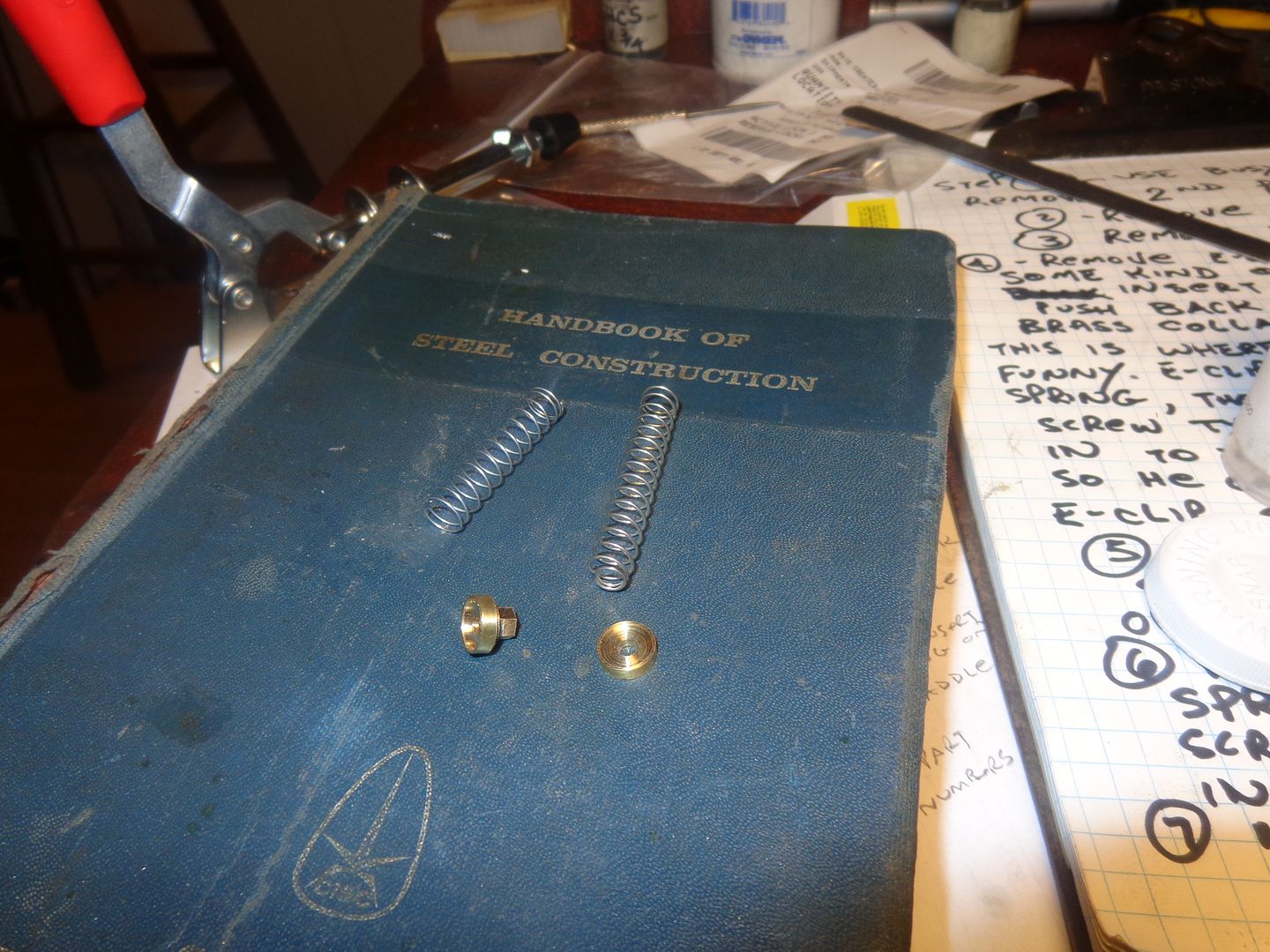
Nothing really exciting or high-tech to post about tonight. Just a couple of valve spring keepers. The intake valve keeper is reamed to .125", the exhaust valve keeper is threaded #5-40 (And yes, that IS a hex machined onto the back side of it.). I picked up the springs at Brafasco while I was running all over town getting quotes for a customer, and managed to work 6 hours in my office on a design job.
 
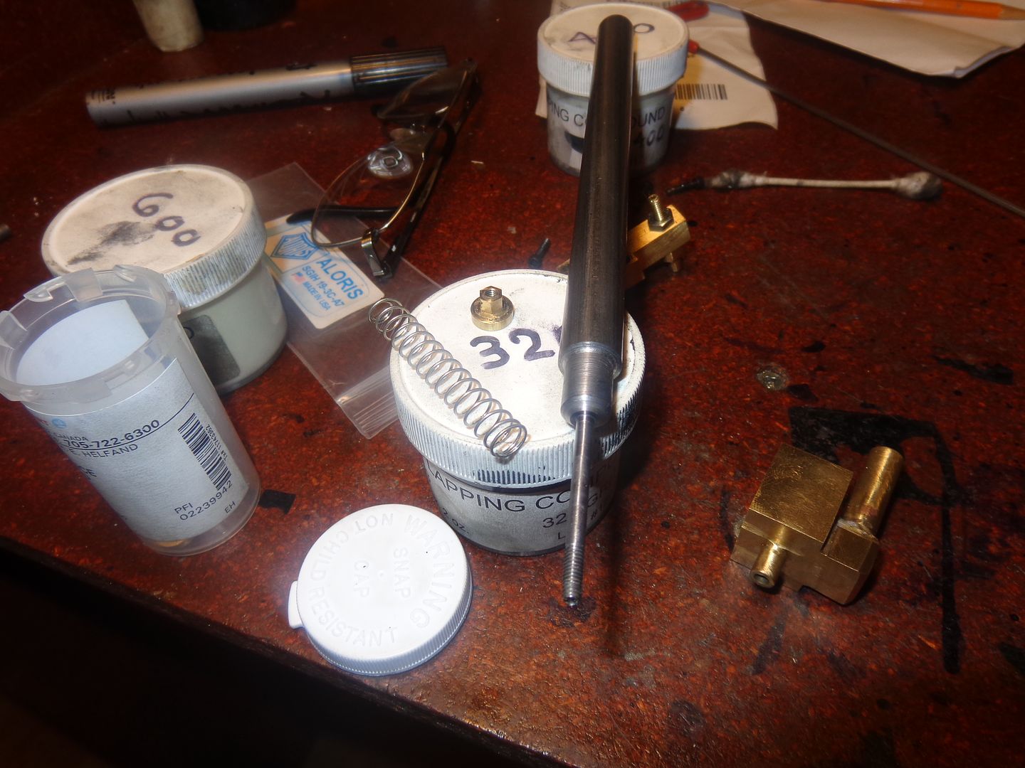
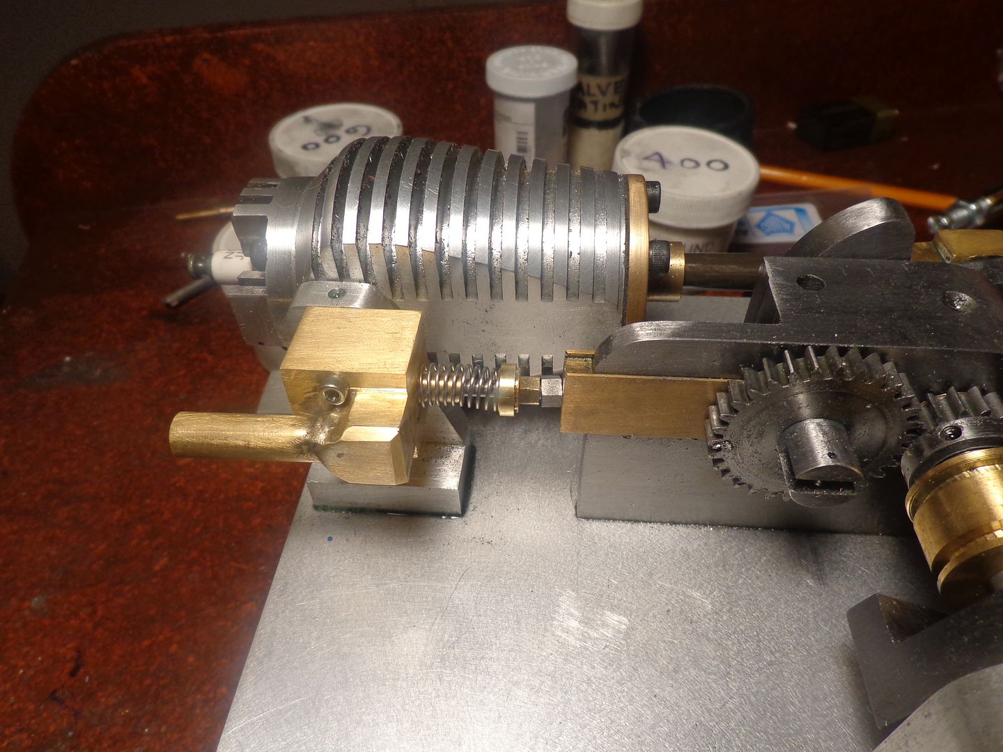
I just had a very exhausting time this afternoon!! Okay, I know, horrible pun!! I turned the exhaust valve from cold rolled 1/2" diameter steel, and left it attached to the parent metal until I had a chance to lap it into the valve seat with #400 then #600 lapping paste. I know it is setting on a tub of 320 grit, but I didn't actually use any of that---it was just holding up the valve for a picture. After trying the "Blow your guts out thru the exhaust pipe test" to convince myself that the valve was really going to seal, I cut the valve away from the 1/2" cold rolled rod and installed it in the exhaust valve body, along with the spring, keeper plate, and lock nut. I left about .025" clearance between the locknut and the brass valve lifter, when the lifter is not "up" on the cam.

 
:eek:Dang!! I didn't notice how crooked that lock nut was setting until after I had posted the picture!! I took it off, turned it around, and put it back on. It's setting straight now, but you're going to have to take my word for it.
 
I found a precious hour this morning to whittle out an intake valve, lap it, and install it in the intake housing. I still have to make paper gaskets to go between the intake and exhaust housings and between the exhaust housing and the pillar it bolts against. I have never had much luck with the "gasket in a tube" stuff by Permatex nor anyone else.---Perhaps that is because I end up taking things apart and putting them back together again about 40 times before I'm actually finished!!!
 
And today we have the needle valve, complete with needle silver soldered to adjusting knob. It works.--I can blow a stream of air through the jet from the gas line end with my mouth firmly puckered around the fuel inlet.---As I close the needle valve with my fingers, it gets harder and harder to blow until finally it seals completely. Tomorrow it will be time to build gaskets.
 
Last edited:
I'm still watching as well Brian. Unfortunately life get's in the way of even replying.

I am looking forward to it running.

Tom

PS ... How do you like the new mill?
 
Wife is having a nap---I kept working!!! Gaskets are made and installed. Valve timing is set. When spun by hand, I am getting a bounce back on compression stroke. Not a lot of bounce back, but it's there. Holy Cow---All that's between me and a running engine is the starter ring which bolts to the flywheel to let me engage my variable speed drill as a starter!!! I can borrow a gas tank of one of my many other i.c. engines.---Getting excited now!!!
 
I'm on the edge of my seat - is there anything more exciting than anticipating the first 'bang'?
 
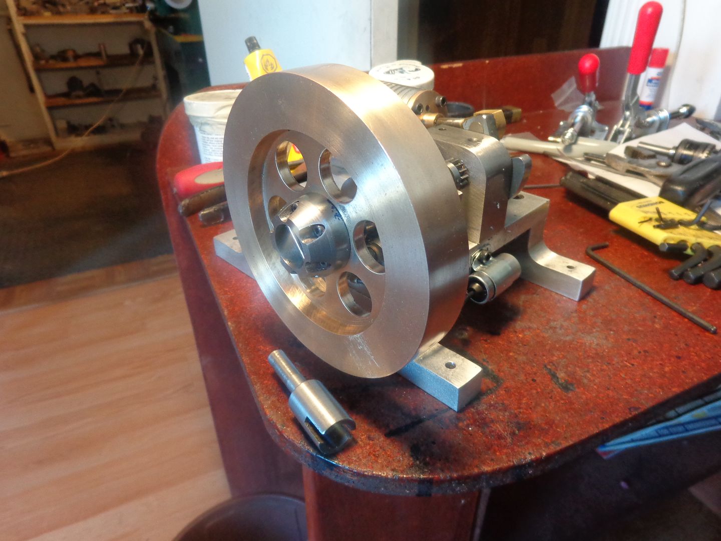
Today's offering to the Machine Gods consists of a starter hub, the part which fits into my variable speed drill to engage the starter hub, and a mounted condenser. I have set the valve timing and the ignition timing. The ignition points and cam are hidden in behind the hub of the flywheel.
 
Now is the difficult time. The engine is ready to run. I have gas tanks which I can "borrow" from many of my other engines. The issue is that this type of engine has no throttle. It is designed to run "wide open" or "full throttle". The device which controls the RPM is the hit and miss lockout lever and the centrifugal governor. There is nothing that quite compares to starting one of these engines without the governor set up in place. First you wonder if it will start and run. Then, in one terrifying burst you wonder if you will be able to shut it off before it over revs and explodes. This all happens in a matter of nano-seconds, and it scares the crap out of you. I will make the lockout lever and install it before I try to start this engine. There is a spring required to control the centrifugal weight, and I think the spring I currently have in place is too light. I went to Brafasco and raided their spring collection, but the only spring that would actually fit the hole prepared for it is the spring out of a ball point pen. The strength of this spring is critical to the way the engine runs. If the spring is too light, the governor weight will fly out and engage the exhaust valve lifter at too low an rpm, and the engine won't have enough speed to keep running. If the spring is too strong, the governor weight won't fly out and engage the exhaust valve lifter until the engine reaches warp speed. And the only way you will know if the spring is too light or too strong is to start the engine and find out!!! At least I have progressed from having to pull the spark plug wire off and risk electro-shock therapy. I have a kill switch on my "power box" which has the 12 volt coil in it.
 
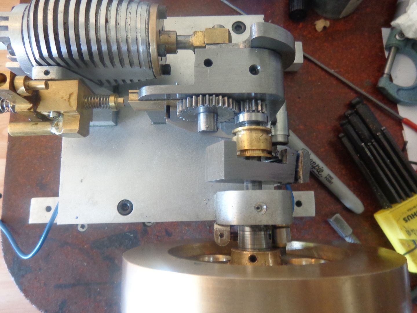
So---How good are your eyes? In the first picture, the counterweight on the centrifugal governor has pivoted and swung outward from centrifugal force, causing the brass spool to slide along the crankshaft, which makes the hit and miss catch lever pivot and swing in under the 1/8" diameter split pin in the bronze valve lifter. This prevents the exhaust valve from closing, so the engine remains in the "miss" cycle as long as the engine rpm is high enough to keep the governor weight swung out like that. In the second picture, the engine has slowed down enough that the spring captured between the governor weight and the governor weight support has caused the governor weight to pivot and swing back in, which moves the brass spool the other way, thus causing the hit and miss lever to pivot the other way and swing out from under the split pin, which now lets the exhaust valve lifter follow the cam and let the exhaust valve close to build compression as the engine continues to rotate because of the flywheel. In this state the engine will then fire and start the whole cycle over again. There is some very fussy work in getting all of this to happen freely in a static position.

 
I have a fix for this, but it will take a while. The counterweight and counterweight support bracket are exactly as designed by the original designer, Philip Duclos, and the hole for the spring is only 0.172" in diameter. I can open this up to 0.219" safely, which will allow for a larger, stronger spring. Before I modify anything though, I will go back down to Brafasco and make sure they have larger stronger springs that will fit into a 7/32" diameter hole. Then I have to remove the flywheel, the ignition cam, and the crankshaft support bearing to get the counterweight support bracket off to work on it and enlarge the hole in it and in the counterweight.
 
Hi Brian
Maybe this will work for You?? Lay a shim at the shown place?
Brian Rupnow Hit and Miss 001.JPG
Regards
Gerhard
 
It's all looking great, although I can't make out where the governor spring fits, I know that you said it's a compression spring, so it's working to push the governor closed.

Paul.
 
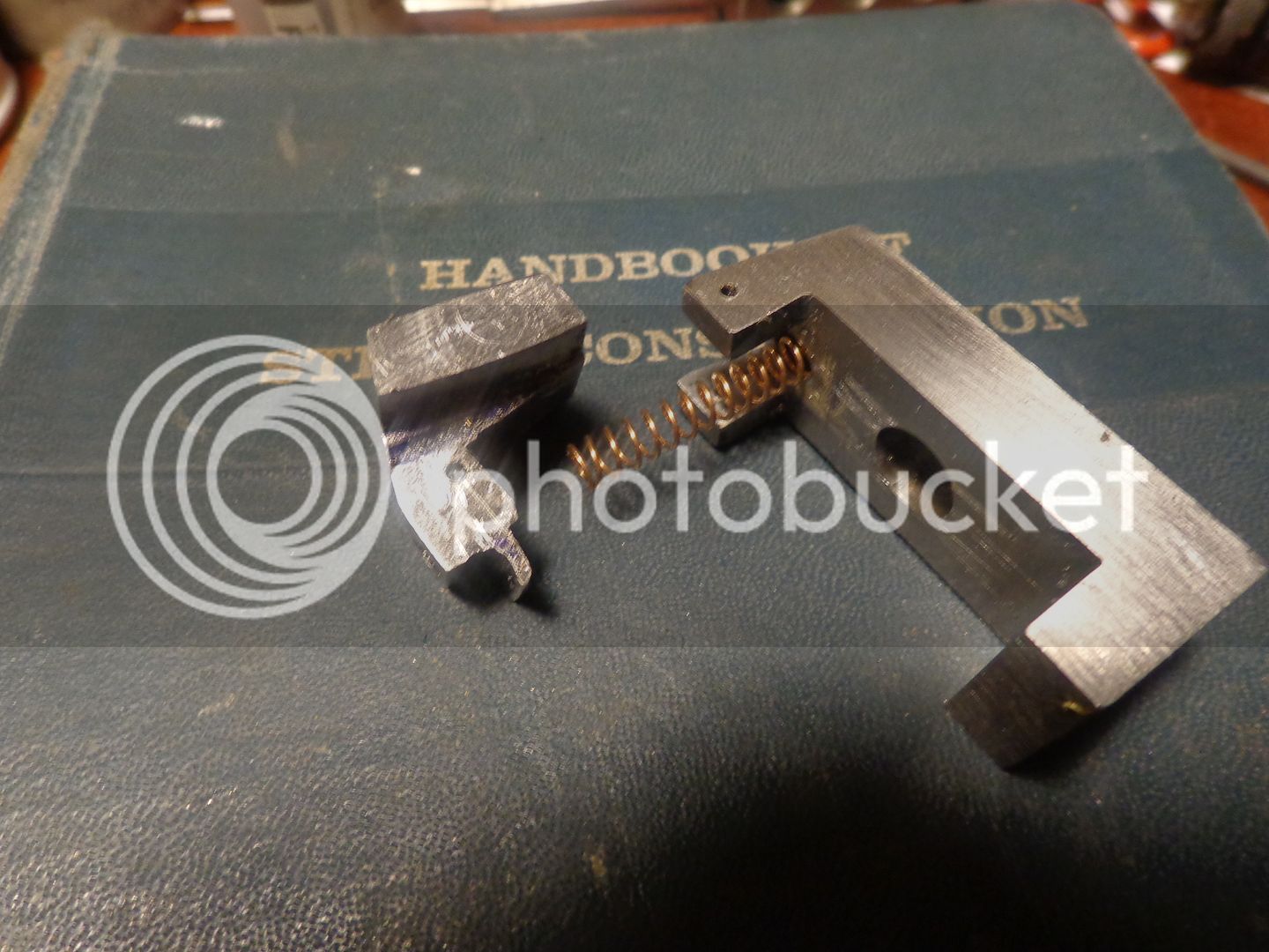
I went to Brafasco and bought 3 springs that would fit into a 7/32" diameter hole in a "test piece" I had made. I got a light spring, a medium spring, and a heavy spring. I removed the governor and enlarged the hole that holds the spring to 7/32" diameter. Then I installed the medium spring (the copper colored one). For those of you who asked about the centrifugal governor, I have included shots of the governor bracket that is fixed to the crankshaft with a set screw, and the governor weight which swings out under centrifugal force to move the brass spool. You can see it before and after assembly. It pivots on a 1/16" diameter pin.


Latest posts

Back
Top