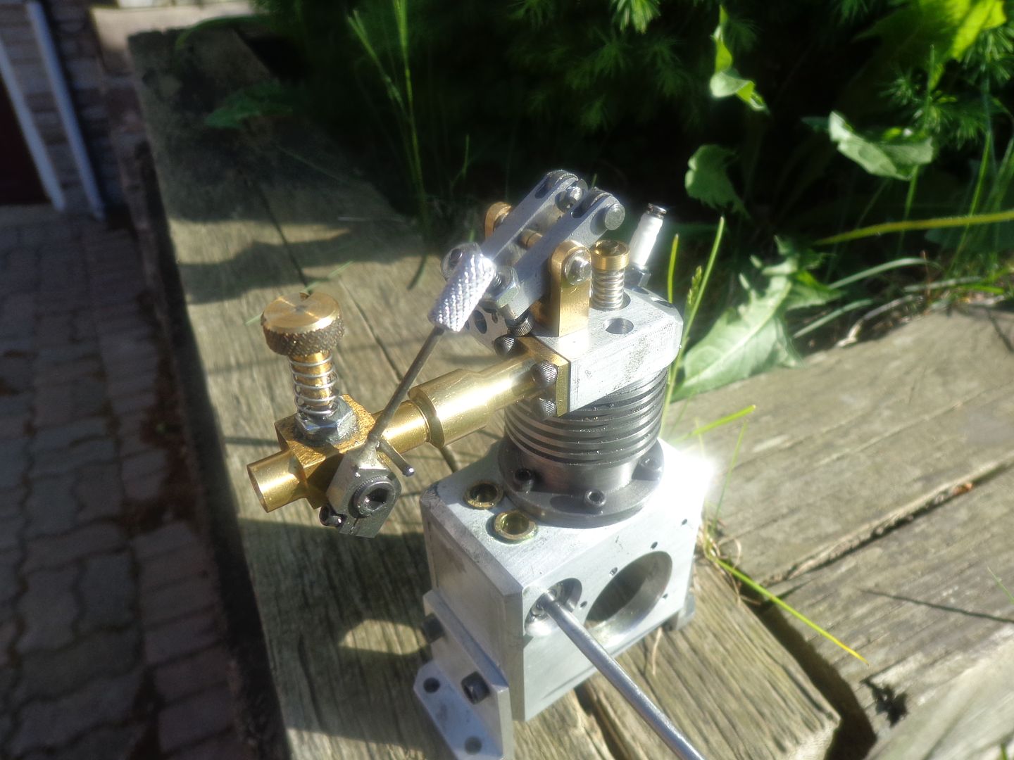
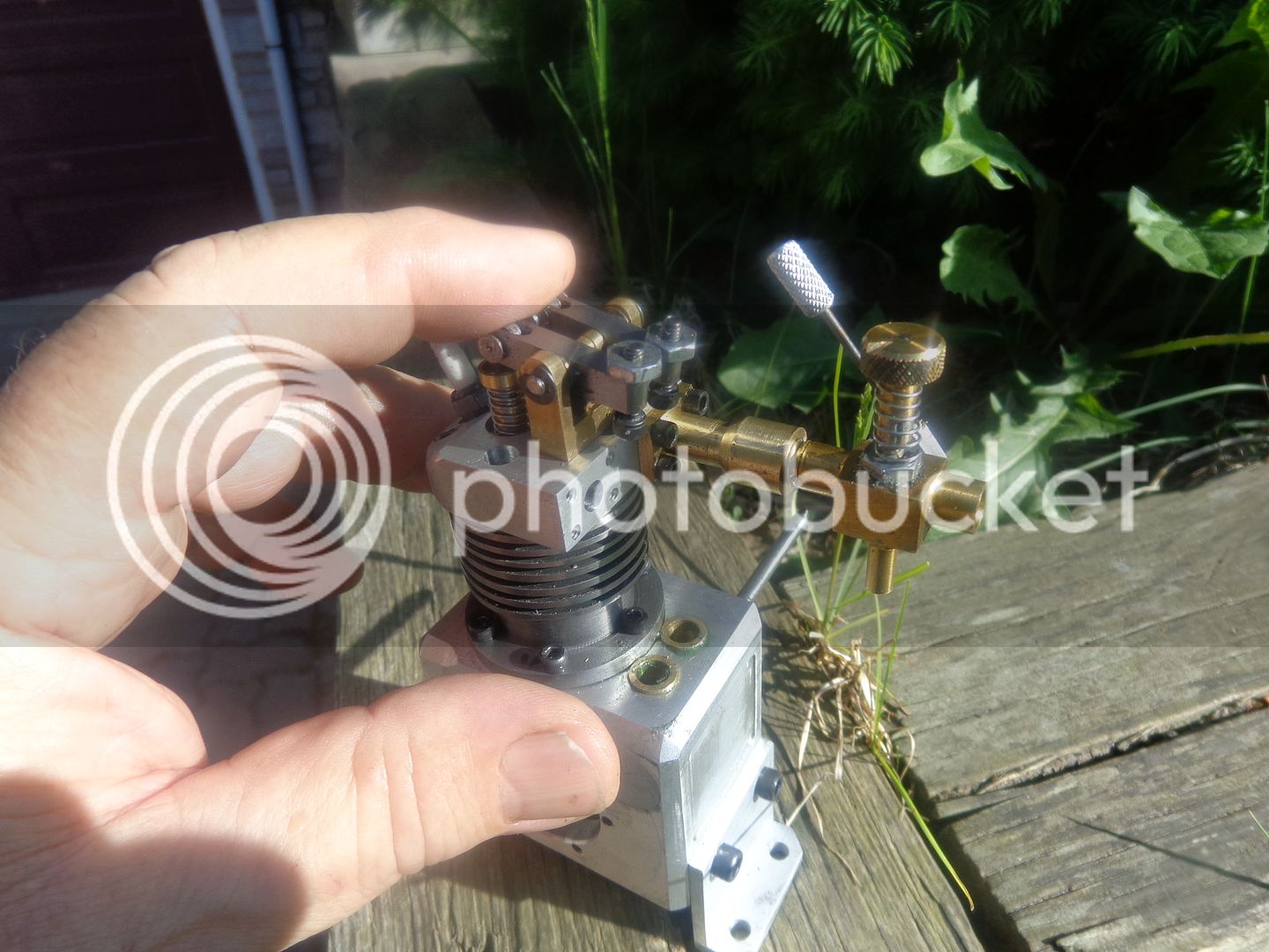
Today was just too beautiful outside to spend the whole day in my shop. It was 86 degrees F and all sunshine today. I did however sneak in for a couple of hours this afternoon and Loctited the first cam to the camshaft---a messy, nasty business, and Damn, I hope I got it in the right place. There isn't much room to work inside that crankcase, even with the crankshaft removed. I also managed to finish the intake manifold, bolt it in place, and install a Chuck Fellows carburetor on it. I'm not sure of the proportions---It looked okay on the solid model, but it kind of looks like a long necked goose in person. Perhaps when I get the rest of the engine back together things will look better proportion wise. I may have to put a spacer under my rocker arm support--the rocker arms are running uphill on quite a pronounced angle. I am going to be very tight for room between the intake pushrod and the head of the capscrew holding the intake manifold on. I may have to do a little creative counterboring there, although I'm not sure yet. Tomorrow, after the Loctite is thoroughly set up on the first cam, I have to position the second cam rotationally and Loctite it to the shaft.