


peterl95124
Well-Known Member
- Joined
- Feb 22, 2020
- Messages
- 485
- Reaction score
- 315
in DiegoVV's thread "Olsryd Merlin - Feasible?" I posted a picture of my model Merlin,
but I think it would be better to fork off since I didn't start with Oslryd's plans or castings.
DiegoVV asks
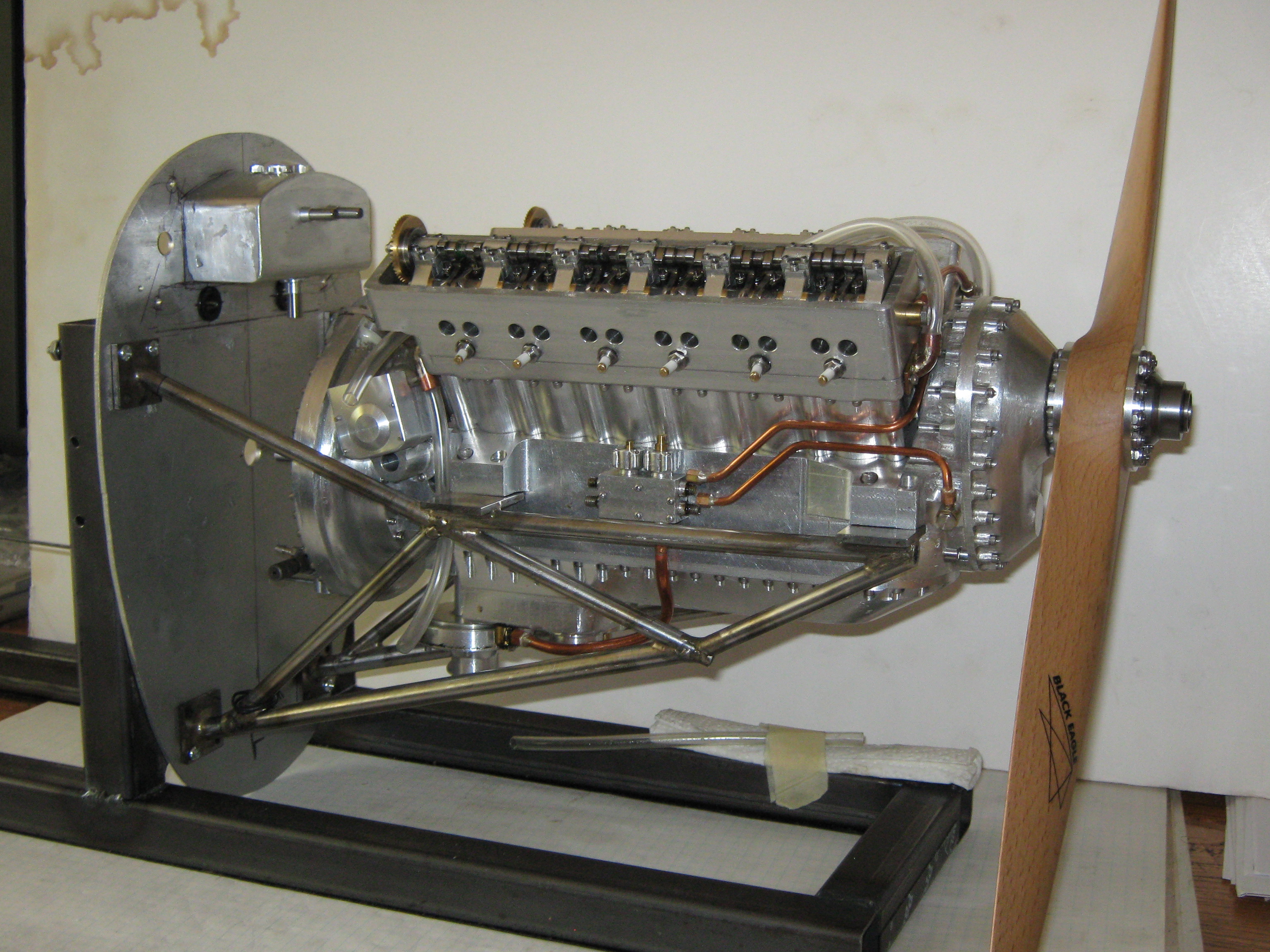
this is my own engine, designed from scratch and built from bar stock, based on cross section drawings in "The Merlin in Perspective" published by the Rolls-Royce Heritage Society which I xerox-enlarged to 1" cylinder bore and then took all measurements from so its as scale accurate as I could make it.
Steve Hazelton made a youtube video of it running at a BAEM-Club meeting, search for "first pop merlin v12".
I would very much like to make the plans available, but currently they are all pencil on paper, so I have a tremendous amount of work to make them readable and reproducible, and many of them only make sense to me (X-ray-vision drawings where things at different Z depths show up in the same drawing, a big no-no in classical drafting but that's how I do it anyway).
In the best of all worlds I'd author a book like Kozo's "Pennsylvania A-3 Switcher" which I have and greatly admire, more realistically maybe something along the lines of Bruce Satra's plans and construction notes for his O-440 engine, but don't think I have the energy or inclination to do that either, so maybe a plans and construction article sequence in Mike Rhemus' Model Engine Builder, but he would have to CAD my drawings and do much of the writing and I don't know if he still has the energy to do that, we're at least talking about a presentation article as he wants to take a cover-photo of it.
needless to say this is not a beginner project, and some parts are so complicated (intake manifolds, supercharger) that I'm considering getting a CNC mill and making those for folks that see them as too challenging, and that would depend on how much interest there was (as otherwise I have no desire for CNC). And I built my own cam shaft grinder so I'd offer those as well. The parts that are manufactured are screws, gears, ball bearings, and springs, everything else if made from bar stock. it does take a lot of determination and motivation to for example make 48 valves and rocker arms, 24 spark plugs, 36 piston rings, and 12 pistons, conrods and cylinder liners, but as the saying goes "a journey of a thousand parts starts with a single cut".
I must also add that if you are familiar with Barry Hares' model Merlin engine, this isn't anywhere near that detailed, and I'm not anywhere near that capable, my aim was to make something that an ordinary home shop machinist could do (and some will argue with whether I succeeded), I'd call this "stand off scale", it has all the correct proportions but I simplified things for manual machining, for example you won't see any casting artifacts that are on real full size engines (that Barry Hares did duplicate).
anyway, those are some of my thoughts, my goal is to get this design out there for other folks but still don't know how that will happen.
but I think it would be better to fork off since I didn't start with Oslryd's plans or castings.
DiegoVV asks
I fully agree, If I put the effort it takes, I would make it as closer as the real Merlin as my capabilities allow me. Where did you get this picture? Is it a modified Olsryd? Is there any available plans?
this is my own engine, designed from scratch and built from bar stock, based on cross section drawings in "The Merlin in Perspective" published by the Rolls-Royce Heritage Society which I xerox-enlarged to 1" cylinder bore and then took all measurements from so its as scale accurate as I could make it.
Steve Hazelton made a youtube video of it running at a BAEM-Club meeting, search for "first pop merlin v12".
I would very much like to make the plans available, but currently they are all pencil on paper, so I have a tremendous amount of work to make them readable and reproducible, and many of them only make sense to me (X-ray-vision drawings where things at different Z depths show up in the same drawing, a big no-no in classical drafting but that's how I do it anyway).
In the best of all worlds I'd author a book like Kozo's "Pennsylvania A-3 Switcher" which I have and greatly admire, more realistically maybe something along the lines of Bruce Satra's plans and construction notes for his O-440 engine, but don't think I have the energy or inclination to do that either, so maybe a plans and construction article sequence in Mike Rhemus' Model Engine Builder, but he would have to CAD my drawings and do much of the writing and I don't know if he still has the energy to do that, we're at least talking about a presentation article as he wants to take a cover-photo of it.
needless to say this is not a beginner project, and some parts are so complicated (intake manifolds, supercharger) that I'm considering getting a CNC mill and making those for folks that see them as too challenging, and that would depend on how much interest there was (as otherwise I have no desire for CNC). And I built my own cam shaft grinder so I'd offer those as well. The parts that are manufactured are screws, gears, ball bearings, and springs, everything else if made from bar stock. it does take a lot of determination and motivation to for example make 48 valves and rocker arms, 24 spark plugs, 36 piston rings, and 12 pistons, conrods and cylinder liners, but as the saying goes "a journey of a thousand parts starts with a single cut".
I must also add that if you are familiar with Barry Hares' model Merlin engine, this isn't anywhere near that detailed, and I'm not anywhere near that capable, my aim was to make something that an ordinary home shop machinist could do (and some will argue with whether I succeeded), I'd call this "stand off scale", it has all the correct proportions but I simplified things for manual machining, for example you won't see any casting artifacts that are on real full size engines (that Barry Hares did duplicate).
anyway, those are some of my thoughts, my goal is to get this design out there for other folks but still don't know how that will happen.
Attachments

Last edited:
") !
!


