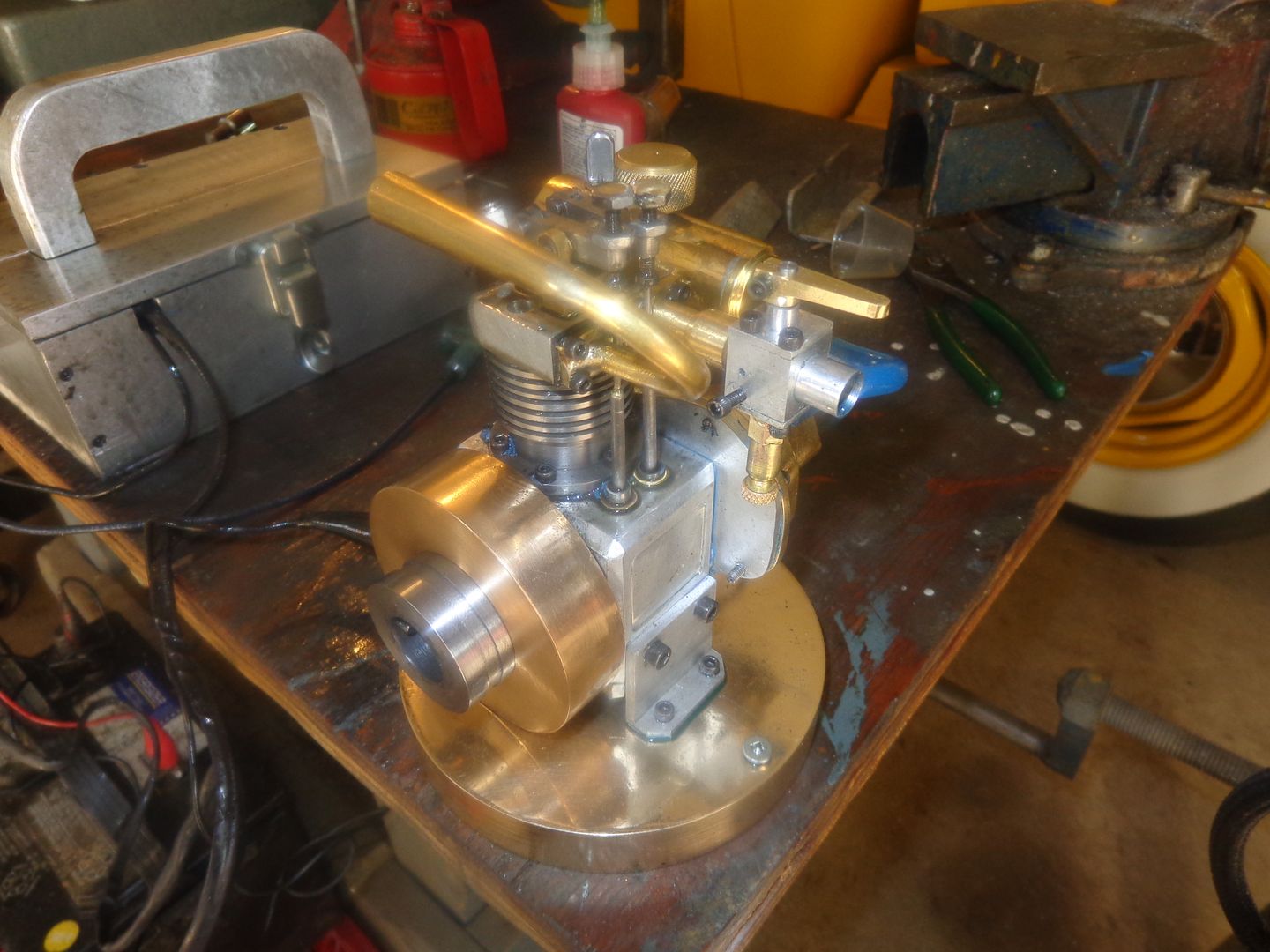
As you are probably all aware, I have just finished a two month build of my version of Malcolm Stride's engine, the Jaguar, which is essentially half of a Bobcat. My engine ended up with many changes, and got rechristened the Canadian Cub. It is a sweet little engine, with a totally enclosed crank-case and an oil sump and splash lubrication. The only trouble is, the engine runs terribly hot. Malcolm ran his with a propeller, which no doubt kept it cool thru the air movement the propeller created. I am afraid of propellers, because at hi speed they become somewhat invisible, and have a tendency to cut off fingers from old fools who inadvertently stick their fingers in the invisible propellers at speed!!! THUS--I have determined to create a small. belt driven cooling fan to keep the temperature down into a reasonable range on my engine. I haven't seen any posts before on similar subjects, so you may find this of interest.

You are using an out of date browser. It may not display this or other websites correctly.
You should upgrade or use an alternative browser.
You should upgrade or use an alternative browser.
Cooling Fan for Model I.C. Engine
- Thread starter Brian Rupnow
- Start date


Help Support Home Model Engine Machinist Forum:
This site may earn a commission from merchant affiliate
links, including eBay, Amazon, and others.
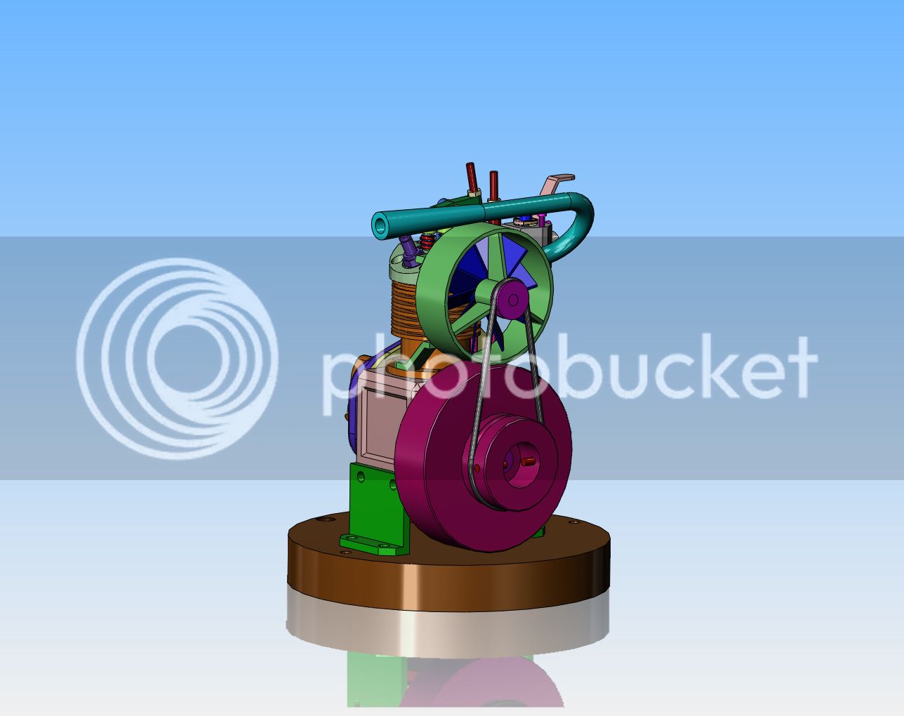
As you can see, my engine is not very big, being only about 5 1/2" (140 mm) tall, with a 3" (76 mm) diameter flywheel. This only leaves me 2 1/2" (63 mm) for a fan and fan shroud, as I only want to cool the cylinder and cylinder head. The crank-case is not overheating, and a larger fan would completely overwhelm the engine.

My original thoughts were to use a computer fan, which is close to the right size. Unfortunately, computer fans are all driven by a D.C. motor, and the fan hub is part of the motor housing. This leaves you with an enormous center hub and very little blade. I need airflow in that center area, so decided to search for a small (2") diameter fan with a small hub.


Fortunately for me, I was able to find a 2" diameter 10 blade fan with a small hub and a 3/16" (5 mm) center bore with set screws. The pitch is correct to blow air over the cylinder when driven clockwise, which is the rotation of my engine.


At speed, I am sure that this little aluminum fan would wreak bloody mayhem with unsuspecting fingers as well, so it will have a shroud fitting around it, which I will make from 2 1/16" i.d. steel auto exhaust tubing. The center hub will be a piece of 1/2" (13 mm) o.d. mild steel, with a bronze bushing of 3/16" pressed into it, and the hub will be supported concentric to the outer rim with 3 pieces of 1/16" (1.5 mm) mild steel plate welded or silver soldered into place. The shaft and pulley will be turned from one piece and the groove in the pulley will line up with the groove in the starter hub on the face of the flywheel. I will use a 3/32" diameter rubber o-ring for my drive belt, and the fan will turn at roughly twice the engine speed.

The fan shroud will be supported by a couple of brackets which pick up one of the cylinder head bolts and one of the cylinder to crank-case bolts. These brackets will again be made from 1/16" mild steel and silver soldered or brazed into place. The fan shaft is cantilevered out the side away from the engine cylinder, so the fan should be easy to install in the shroud from the non bearing side. When installed on the engine, the cylinder itself will serve to keep pokey fingers out of the fan. I believe that since the engine itself is all built from brass and aluminum, I may resort to painting the fan and supporting shroud---possibly red for the fan and flat black for the shroud itself.

Last edited:
This is the engine which the fan will be installed on. I am just waiting now for the fan itself, which is supposed to take a week to get here when ordered from Acklands of Canada.

Well Damn!!!---And I do mean that with all my heart. I got a call today from Acklands that my fan had come in, so I rushed right over. The diameter was right. The hub bore was right.---But the direction of pitch was exactly opposite of the picture showed on their web page!!! I pointed that out to the lady on the counter, who immediately told me that was no problem---just turn the fan around. I think I was able to get it through her head that it wouldn't make any difference. Only changing the direction of rotation would make the fan blow instead of suck!!! She seemed a bit dazed, but said she would return it and there would be no charge. So---I guess I will build my own fan after all. Already ideas are percolating through my head. I would rather use brass than steel, because the hub and blades have to be silver soldered together, and I find the brass a tiny bit easier to silver solder, plus the color of the silver solder matches the blade color.---Brian
Well---That doesn't look so bad!! The hexagon hub measures 0.541" across the flats x 3/8" long, the blades are .430" x 1/16" x 0.729 long. Overall diameter is still 2". I have shown the fabricated fan in a second model beside the overall assembled model to show better what it looks like. Of course, this will require some kind of jig to hold the blades in exact position while I solder them to the hub.


Okay--this will work for a soldering jig. My only concern is that after I get one blade soldered on, will the heat from soldering the next one on make the first blade fall off. I can avoid this to some extent by cooling the assembly off between blades and "skipping around", but as more blades get added, this becomes harder to do.


Swifty
Well-Known Member
Good luck with the soldering Brian, have you thought of making a fan out of sheet brass, cut the radial lines down to the hub and bend the blades to suit. This would make the blades one piece, so soldering on to a hub will be no problem.
Paul.
Paul.
I thought about it Paul. A quick check of my brass drawer shows that I have all the material I need for a fabricated fan. I will try the fabricated design first. If it doesn't work, well, then we will try the one piece design you are suggesting.
Silver soldering shouldn't be a problem. The heat required to remelt solder is quite a bit higher than first time melting. There is a proper name for that, but I can't remember it!
Do you have any rockwool or fibreglass wool or other insulating material? As an insurance, you could use that as a blanket to protect the already soldered joints. I've even heard of potatoes used as a heat sink. Slide a slice of potato over the already soldered blades.
If the blades are going to be slotted into the hub, do you really need silver solder? Low melting temp solder would be perfectly strong enough.
Dave
The Emerald Isle
The jig worked very well. It looks a bit crude in these shots, but it did keep everything aligned while I silver soldered the blades to the hub. Heat from soldering the blades on did not cause the solder on previously soldered blades to let go and have the other blades fall off. (I have experienced that kind of thing when working with soft solder.)


Needless to say, there was a lot of clean-up, filing, and sanding required to get the fan into any kind of presentable shape. It looks pretty ragged in around the actual solder joints, but the blades are really solidly attached and the hub area will be hidden by other components when this is assembled. Only the blades will be visible.


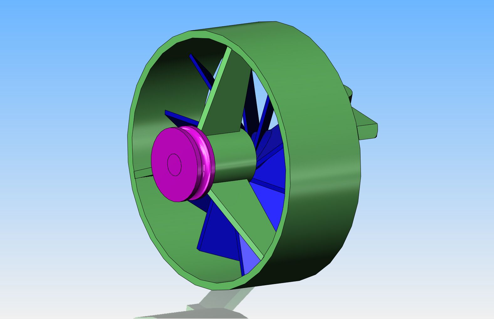
This is what the fan will look like when mounted in the protective ring that goes around it, with the hub which supports the shaft bushing setting in front of it.


I'm done to the point where I need to make up the shroud that surrounds the fan. I have the outer rim from mild steel, and the hub from mild steel. I have some 1/16 #316 stainless steel for the 3 "spokes" between the inner hub and outer ring, but I don't know whether or not I can braze it.---But I will in about 10 minutes. Fortunately the piece I have is quite large. I will snip off a couple of pieces and conduct a test.
And the answer is--The 316 S.S. can be brazed or silver soldered equally well. In the picture, the part on the left has been brazed using oxy acetylene and flux coated brazing rod. The item on the right has been silver soldered with the paste flux being applied to the joint first. The silver solder seems to flow out better, requiring less clean-up after the fact. The brazed joint had a lot of small "welding berries" around the main weld, which required clean-up with a grinding disc.---Which is fine when working on automotive car bodies, but not really desirable for model work. So, my question is answered. I will use the 1/16" stainless steel for my spokes and silver solder the joint. That is a good thing, otherwise I would have had to go down street and buy some 1/16" mild steel material.


Last edited:
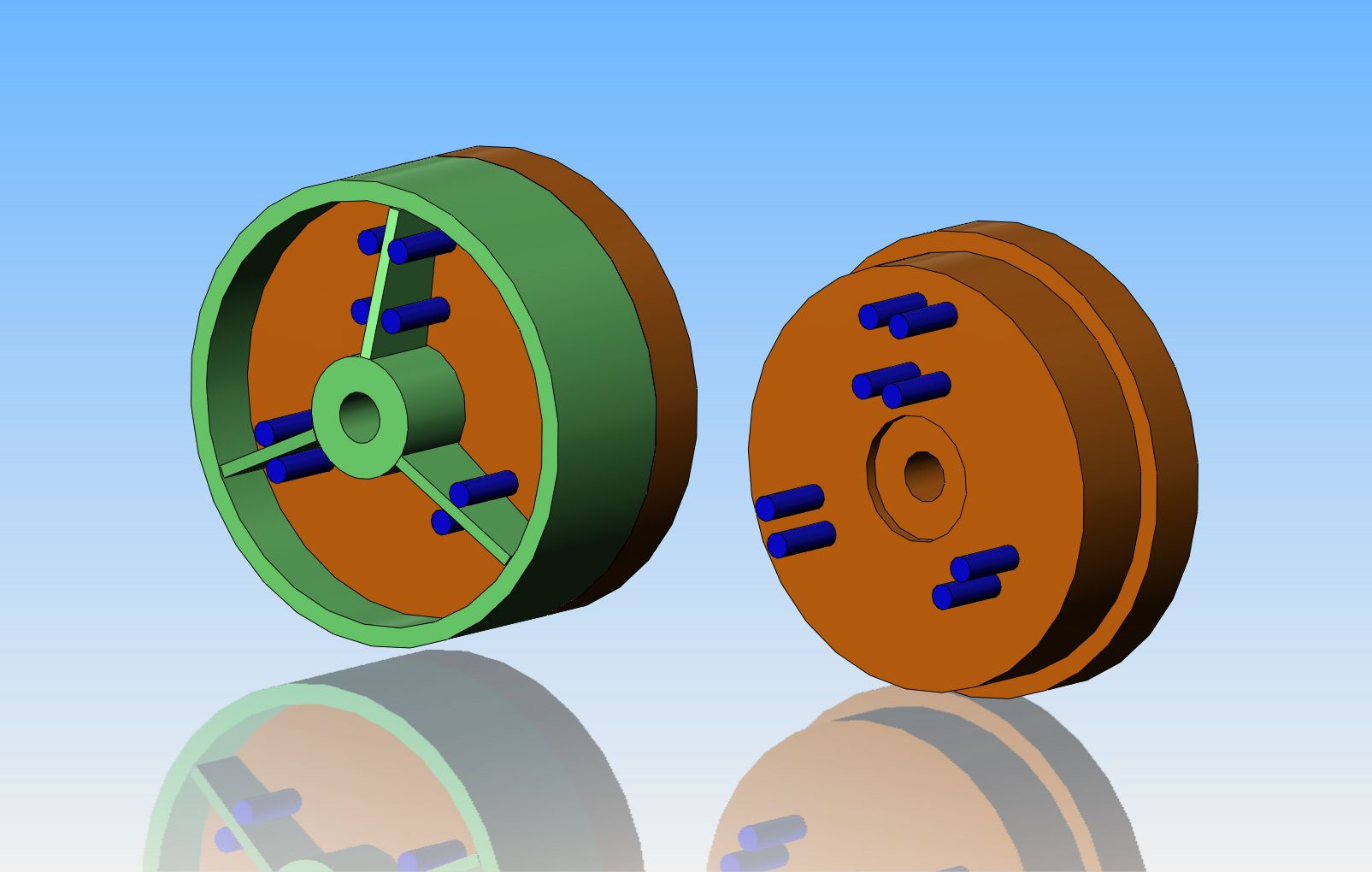
This is going to be one of those situations where the jig to hold the pieces in alignment for silver soldering will be as complex as the soldered assembly. The central hub must be held concentric to and parallel to the outer rim, and the 3 "spokes" will be set at 120 degrees apart. Fortunately, the "jig" is mostly lathe work with some accurately placed holes. The position with 4 blue posts is the actual soldering station. The other two positions are intended to let me turn the part in the jig and maintain the 120 degrees between spokes.--In fact, looking at it as I post this, I probably only need one of the double post stations at 120 degrees to the main "soldering" station.

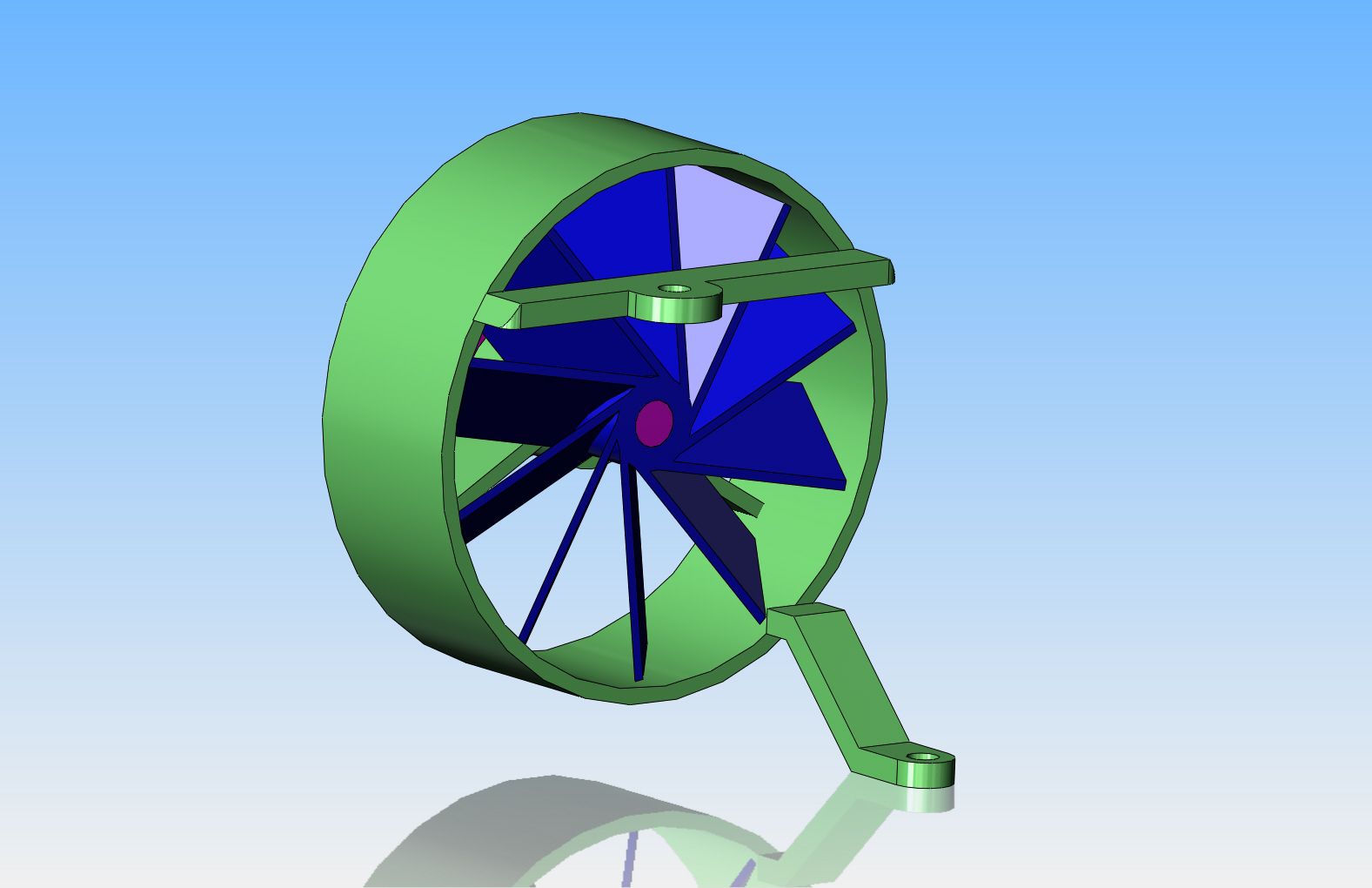
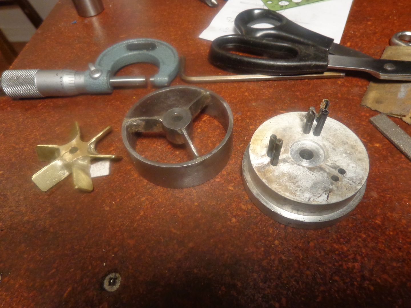
That all went surprisingly well. The jig was a lot of work, but it held everything located very well. I didn't even bother removing the soldered parts from the jig, just set all 3 spokes in place (all of the locating pins were in the jig) and put enough of a tack at each end of each "spoke" to hold everything solid. Then I removed the shroud from the jig and tacked everything on the back side, then went around and soldered everything solid. It was more work cleaning it up afterwards than it was doing the soldering. I didn't get too crazy with the clean-up, because the shroud is going to get painted flat black when all of the brackets are soldered onto it. This pictures shows the jig, the shroud, and the fan, from the front side.(The side facing away from the cylinder.) and one shot from what will be the side facing the cylinder..


Similar threads
- Replies
- 13
- Views
- 7K
- Replies
- 319
- Views
- 72K